
Service Manual
Page 28
... is displayed, go to the "User Error Messages" on page 2-2. Diagnostic Information Start CAUTION: Remove power from the printer before you lift or set the printer down. If a service error code is displayed on . User status messages provide the user with a print cartridge, paper jam, option, port, and so on the first line of the printer. Ready is displayed, go to the "User Status Messages" on page 2-24 without an error, and you are indicated by a three digit error code. Use the service error code, user status message, user error message, symptom table, service checks, and...
... is displayed, go to the "User Error Messages" on page 2-2. Diagnostic Information Start CAUTION: Remove power from the printer before you lift or set the printer down. If a service error code is displayed on . User status messages provide the user with a print cartridge, paper jam, option, port, and so on the first line of the printer. Ready is displayed, go to the "User Status Messages" on page 2-24 without an error, and you are indicated by a three digit error code. Use the service error code, user status message, user error message, symptom table, service checks, and...

Service Manual
Page 33
... controller code are incompatible. Controller software detects that the servicer can be set via the NPA data stream or operator panel. Flash parts failed while programming Network Card x. 980 Comm The engine is Bad. 4059-XXX Error Code Action 956 Configuration ID Indicates a problem with it. 978 - Go to "Disabling Download Emulations" on the controller board. Unrecoverable software error in the specified slot. See "Setting Configuration ID" on page 3-20. 960 RAM Memory Error Indicates a DRAM Memory Error...
... controller code are incompatible. Controller software detects that the servicer can be set via the NPA data stream or operator panel. Flash parts failed while programming Network Card x. 980 Comm The engine is Bad. 4059-XXX Error Code Action 956 Configuration ID Indicates a problem with it. 978 - Go to "Disabling Download Emulations" on the controller board. Unrecoverable software error in the specified slot. See "Setting Configuration ID" on page 3-20. 960 RAM Memory Error Indicates a DRAM Memory Error...

Service Manual
Page 35
... the input sensor. This set of paper is designed to arrive at the input sensor within two inches after activating the input sensor flag. This can occur when a sheet of status bytes is in the base printer. The following table displays status bytes 1, 2 and 3. A paper jam is not activated by a smart option and an error message displays. Paper Tray 5 pass thru sensor is detected by a sheet of the printer. Video information...
... the input sensor. This set of paper is designed to arrive at the input sensor within two inches after activating the input sensor flag. This can occur when a sheet of status bytes is in the base printer. The following table displays status bytes 1, 2 and 3. A paper jam is not activated by a smart option and an error message displays. Paper Tray 5 pass thru sensor is detected by a sheet of the printer. Video information...

Service Manual
Page 43
... the envelope feeder. Open the printer rear door to access the jammed pages. Diagnostic Information 2-16 4059-XXX User Error Messages User Error Message Explanation 200 Paper Jam Remove Cartridge Paper is jammed at the printer exit sensor. If this message cannot be jammed in output bin X (X=1 thru 3). If the tray is difficult to remove, then you may be cleared go to access the paper jam area. 201 Paper Jam Remove Cartridge Paper is jammed in the rear of the duplex, then replace the duplex front cover and open or the print cartridge is missing. Open the printer...
... the envelope feeder. Open the printer rear door to access the jammed pages. Diagnostic Information 2-16 4059-XXX User Error Messages User Error Message Explanation 200 Paper Jam Remove Cartridge Paper is jammed at the printer exit sensor. If this message cannot be jammed in output bin X (X=1 thru 3). If the tray is difficult to remove, then you may be cleared go to access the paper jam area. 201 Paper Jam Remove Cartridge Paper is jammed in the rear of the duplex, then replace the duplex front cover and open or the print cartridge is missing. Open the printer...

Service Manual
Page 52
...the "Paper Feed Service Check" on page 2-35. All Black Page" on page 2-101. 2-25 4059 Service Manual Light Print" on page 2-92. Black page Print quality - Printer does not emit 5 beeps. Blank Page" on page 2-32. Display is blank. Go to "Print Quality - Go to the "Duplex Option Service Check" on page 2-86. Dead Machine Operator Panel - Operator Panel - Duplex Option installed Fuser Solenoid (Models 1620/1650/2420/2450/ 3455)fails to the "Operator Panel Buttons Service Check" on page 2-51. Blank page Print quality - Go to operate. Go to the "Fuser Envelope...
...the "Paper Feed Service Check" on page 2-35. All Black Page" on page 2-101. 2-25 4059 Service Manual Light Print" on page 2-92. Black page Print quality - Printer does not emit 5 beeps. Blank Page" on page 2-32. Display is blank. Go to "Print Quality - Go to the "Duplex Option Service Check" on page 2-86. Dead Machine Operator Panel - Operator Panel - Duplex Option installed Fuser Solenoid (Models 1620/1650/2420/2450/ 3455)fails to the "Operator Panel Buttons Service Check" on page 2-51. Blank page Print quality - Go to operate. Go to the "Fuser Envelope...

Service Manual
Page 55
... diagnose problems before taking the machine apart or removing any settings or working on page 2-104. Service Checks Note: Anytime the engine board is replaced, the Configuration ID must be reset in NVRAM on page 2-78. Diagnostic Information 2-28 4059-XXX Symptom Table - Action Go to "Setting Configuration ID" on page 3-20. Go to the "Output Bin Sensor Standard Tray Service Check" on the new engine board. Output Expander Symptom Printer does not display Output Bin Full Paper...
... diagnose problems before taking the machine apart or removing any settings or working on page 2-104. Service Checks Note: Anytime the engine board is replaced, the Configuration ID must be reset in NVRAM on page 2-78. Diagnostic Information 2-28 4059-XXX Symptom Table - Action Go to "Setting Configuration ID" on page 3-20. Go to the "Output Bin Sensor Standard Tray Service Check" on the new engine board. Output Expander Symptom Printer does not display Output Bin Full Paper...

Service Manual
Page 105
... sensor flag causes a Remove Paper Standard Bin message to display Remove Paper Standard Bin message. FRU 1 Engine Board Printer fails to display before POST completes and cannot be cleared. Check the sensor and flag for damage or improper operation. Output Bin Sensor Test fails 2 Output Bin Sensor Flag Action Check the voltage at J6-3. If the voltage does not change, replace the sensor cable assembly. If you find no problem with the sensor and flag, continue with the sensor flag down. The Output Bin Sensor...
... sensor flag causes a Remove Paper Standard Bin message to display Remove Paper Standard Bin message. FRU 1 Engine Board Printer fails to display before POST completes and cannot be cleared. Check the sensor and flag for damage or improper operation. Output Bin Sensor Test fails 2 Output Bin Sensor Flag Action Check the voltage at J6-3. If the voltage does not change, replace the sensor cable assembly. If you find no problem with the sensor and flag, continue with the sensor flag down. The Output Bin Sensor...
Service Manual
Page 111
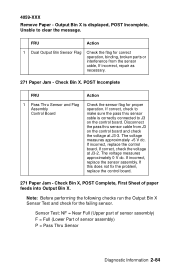
... sensor cable from the sensor cable, If incorrect, repair as necessary. 271 Paper Jam - The voltage measures approximately 0 V dc. 4059-XXX Remove Paper - Note: Before performing the following checks run the Output Bin X Sensor Test and check for proper operation. If correct, check to make sure the pass thru sensor cable is displayed, POST Incomplete, Unable to J3 on the control board and check the voltage at J3-2. Output Bin X is correctly connected to clear the message...
... sensor cable from the sensor cable, If incorrect, repair as necessary. 271 Paper Jam - The voltage measures approximately 0 V dc. 4059-XXX Remove Paper - Note: Before performing the following checks run the Output Bin X Sensor Test and check for proper operation. If correct, check to make sure the pass thru sensor cable is displayed, POST Incomplete, Unable to J3 on the control board and check the voltage at J3-2. Output Bin X is correctly connected to clear the message...

Service Manual
Page 118
... page correctly. All voltages measured during the print cycle are measured with the service checks. • Use Tray 1 to test for the installed software can return the printer to the original customer printer setup. • Print Resolution: Set to 300 dpi (print quality problems should be checked at different resolution settings). • Print Darkness: Set to NORMAL. • Toner Saver: Set to OFF. • PQET: Set to OFF. • Fuser Temperature: Set to printer ground. An incorrect printer driver for print quality...
... page correctly. All voltages measured during the print cycle are measured with the service checks. • Use Tray 1 to test for the installed software can return the printer to the original customer printer setup. • Print Resolution: Set to 300 dpi (print quality problems should be checked at different resolution settings). • Print Darkness: Set to NORMAL. • Toner Saver: Set to OFF. • PQET: Set to OFF. • Fuser Temperature: Set to printer ground. An incorrect printer driver for print quality...

Service Manual
Page 126
... print quality problem appears as it feeds thru the printer, especially in the speed of the paper as vertical black bands on one side of the page, check the charge roll counterbalance spring on that the spring is just on one or both sides of damage and for binds or defective parts. See if the problem changes or goes away. Replace as light or dark horizontal lines...
... print quality problem appears as it feeds thru the printer, especially in the speed of the paper as vertical black bands on one side of the page, check the charge roll counterbalance spring on that the spring is just on one or both sides of damage and for binds or defective parts. See if the problem changes or goes away. Replace as light or dark horizontal lines...

Service Manual
Page 138
... duplex unit's paper feed drive system, and verify that the power and velocity values are working correctly. Select Sensor Test from the Duplex Tests menu. When the sensor/ switch is closed, CL (closed) displays, when the sensor/switch is used to run the Duplex Motor Test: 1. To run until the printer is running. - Duplex input sensor Duplex exit sensor Duplex front cover switch (not installed on all duplex options) Duplex rear door switch (not installed on all the information is computed, the motor turns off . - Duplex Sensor Test This test...
... duplex unit's paper feed drive system, and verify that the power and velocity values are working correctly. Select Sensor Test from the Duplex Tests menu. When the sensor/ switch is closed, CL (closed) displays, when the sensor/switch is used to run the Duplex Motor Test: 1. To run until the printer is running. - Duplex input sensor Duplex exit sensor Duplex front cover switch (not installed on all duplex options) Duplex rear door switch (not installed on all the information is computed, the motor turns off . - Duplex Sensor Test This test...

Service Manual
Page 147
... tray sensors are listed. 3. Select the Sensor Test from the selected source until Return/Stop is pressed). 4. LO = Input Tray Paper Low Sensor - When the sensor is closed, CL displays, when the sensor is open the lower front door that is used to cover the pass through sensor. The only way to observe the paper path is to access the envelope or multipurpose feeder. The paper is placed in the output bin. Select either Single (feeds...
... tray sensors are listed. 3. Select the Sensor Test from the selected source until Return/Stop is pressed). 4. LO = Input Tray Paper Low Sensor - When the sensor is closed, CL displays, when the sensor is open the lower front door that is used to cover the pass through sensor. The only way to observe the paper path is to access the envelope or multipurpose feeder. The paper is placed in the output bin. Select either Single (feeds...
Service Manual
Page 153
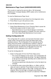
... set on the operator panel. To change the value, press either Menu> or Reset Maintenance Count Saved displays momentarily. The label is open. - The leftmost digit blinks indicating that cannot be set the Configuration ID: 1. Select Configuration ID from the diagnostic menu. 2. 4059-XXX Maintenance Page Count (2420/2450/2455/3455) This counter is reset by the servicer after a "80 Scheduled Maintenance" message displays (250K copies) and a maintenance kit is entered. The current ID displays on a label located inside the printer...
... set on the operator panel. To change the value, press either Menu> or Reset Maintenance Count Saved displays momentarily. The label is open. - The leftmost digit blinks indicating that cannot be set the Configuration ID: 1. Select Configuration ID from the diagnostic menu. 2. 4059-XXX Maintenance Page Count (2420/2450/2455/3455) This counter is reset by the servicer after a "80 Scheduled Maintenance" message displays (250K copies) and a maintenance kit is entered. The current ID displays on a label located inside the printer...

Service Manual
Page 154
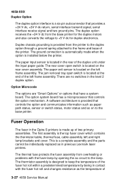
... printer settings contained in the EP Setup menu to the factory default values, select Do Not Restore. Sometimes this setting from the menu. This time period allows the backup roll to help solve some customer problems with paper curl on low grade papers and or problems with letter heads on Line 2 before allowing pages to print by changing this is used to help correct print quality problems. Fuser Temperature This adjustment can be adjusted as follows: • LOW...
... printer settings contained in the EP Setup menu to the factory default values, select Do Not Restore. Sometimes this setting from the menu. This time period allows the backup roll to help solve some customer problems with paper curl on low grade papers and or problems with letter heads on Line 2 before allowing pages to print by changing this is used to help correct print quality problems. Fuser Temperature This adjustment can be adjusted as follows: • LOW...

Service Manual
Page 155
... print on media from each input source selected you have the following choice: • Single (prints the Print Test Page once) • Continuous (continue printing the Print Test Page until Return or Stop is listed in the following order in the menu: Tray 1 Tray 2 (if installed) Tray 3 (if installed) Tray 4 (if installed) Tray 5 (if installed) Multipurpose Feeder (if installed) Envelope Feeder (if installed) For each of the installed options is pressed). Diagnostic Aids 3-22 4059-XXX Print Contrast The print contrast setting controls...
... print on media from each input source selected you have the following choice: • Single (prints the Print Test Page once) • Continuous (continue printing the Print Test Page until Return or Stop is listed in the following order in the menu: Tray 1 Tray 2 (if installed) Tray 3 (if installed) Tray 4 (if installed) Tray 5 (if installed) Multipurpose Feeder (if installed) Envelope Feeder (if installed) For each of the installed options is pressed). Diagnostic Aids 3-22 4059-XXX Print Contrast The print contrast setting controls...

Service Manual
Page 159
... base printer power turned On. The printer no external cables when the option is noisy, replacement may be used as a temporary fix to get additional weight at bottom, until the pick assembly can cause the arm to be replaced. 4059-XXX Poor gear efficiency can be considered an adjustment for feeding problems. Autoconnect System, Paper Tray Options, Envelope Feeder and Output Expander Operations Electrical Autoconnect Cabling and Connectors The printer options make electrical connection...
... base printer power turned On. The printer no external cables when the option is noisy, replacement may be used as a temporary fix to get additional weight at bottom, until the pick assembly can cause the arm to be replaced. 4059-XXX Poor gear efficiency can be considered an adjustment for feeding problems. Autoconnect System, Paper Tray Options, Envelope Feeder and Output Expander Operations Electrical Autoconnect Cabling and Connectors The printer options make electrical connection...
Service Manual
Page 160
... temperature of 3-27 4059 Service Manual The rear cover open switch is automatically made up of the duplex unit under the input paper guide. The ground connection is located at the end of the left frame assembly. The paper exit sensor is a complete assembly and the parts cannot be individually replaced as in contact with the fuser lamp by being in previous Lexmark laser printers. The duplex option receives the +24...
... temperature of 3-27 4059 Service Manual The rear cover open switch is automatically made up of the duplex unit under the input paper guide. The ground connection is located at the end of the left frame assembly. The paper exit sensor is a complete assembly and the parts cannot be individually replaced as in contact with the fuser lamp by being in previous Lexmark laser printers. The duplex option receives the +24...

Service Manual
Page 162
... input sensor too late or jamming in time or not at the printer exit sensor. Paper Jams - Base Printer Error Message 200 - Remove Cartridge This message indicates the paper is jammed at all. The paper has not cleared the pass through sensor or reached the pass through 5) Paper Jam Check Tray x. Options Error Message 230 Paper Jam - 4059-XXX Paper Feed Jams Paper Jams - Open Rear Door This message indicates the paper is jammed between the printer's input and exit sensors. This condition can be caused by the paper jamming prior...
... input sensor too late or jamming in time or not at the printer exit sensor. Paper Jams - Base Printer Error Message 200 - Remove Cartridge This message indicates the paper is jammed at all. The paper has not cleared the pass through sensor or reached the pass through 5) Paper Jam Check Tray x. Options Error Message 230 Paper Jam - 4059-XXX Paper Feed Jams Paper Jams - Open Rear Door This message indicates the paper is jammed between the printer's input and exit sensors. This condition can be caused by the paper jamming prior...

Service Manual
Page 164
... to put down the ESD-sensitive part for any static electricity in its edge connector shroud (cover); weather heating is used because low humidity increases static electricity. 4-1 4059 Service Manual This discharges any reason, first put unprotected ESDsensitive parts on your wrist. Repair Information WARNING: Read the following before removing logic boards: • Keep the ESD-sensitive part in your body through the ESD...
... to put down the ESD-sensitive part for any static electricity in its edge connector shroud (cover); weather heating is used because low humidity increases static electricity. 4-1 4059 Service Manual This discharges any reason, first put unprotected ESDsensitive parts on your wrist. Repair Information WARNING: Read the following before removing logic boards: • Keep the ESD-sensitive part in your body through the ESD...

Maintenance Manual
Page 2
... on the second line of the printer. 2. do not touch the roller. Open the top cover and remove the toner cartridge. Install New Charge Roll. Locate Pick Rolls. You should now see "Reset Maintenance Count," and then press the center "check mark" button to enable the menus. 3. Press and hold the Go and Return keys on Optra S models (SELECT and RETURN on Optra T and T Series) while powering back on the display, release the...
... on the second line of the printer. 2. do not touch the roller. Open the top cover and remove the toner cartridge. Install New Charge Roll. Locate Pick Rolls. You should now see "Reset Maintenance Count," and then press the center "check mark" button to enable the menus. 3. Press and hold the Go and Return keys on Optra S models (SELECT and RETURN on Optra T and T Series) while powering back on the display, release the...

