ThinkPad 600 Ram - Lenovo
ThinkPad 600 Ram

View Results Below
Free Lenovo ThinkPad 600 manuals!
Problems with Lenovo ThinkPad 600?
Ask a Question
Free Lenovo ThinkPad 600 manuals!
Problems with Lenovo ThinkPad 600?
Ask a Question
Related Manual Pages
Similar Questions

Upgrading Ram In My Lenovo Ideapad Flex 10
I was curious as to whether one good if needed to , upgrade the ram the their Lenovo ideapad flex 10...
I was curious as to whether one good if needed to , upgrade the ram the their Lenovo ideapad flex 10...
(Posted by Notso1983 2 years ago)

Ram Slots
how many RAM slots were there in Lenovo G50-70 20351 model laptop?
how many RAM slots were there in Lenovo G50-70 20351 model laptop?
(Posted by vennela10karumanchi 9 years ago)

How To Know How Much Ram My Laptop Supports And Which Type?
i'm using Lenovo S100 ideapad.My RAM is 2GB.I want to upgrade my RAM to 4GB.I want to know how much ...
i'm using Lenovo S100 ideapad.My RAM is 2GB.I want to upgrade my RAM to 4GB.I want to know how much ...
(Posted by psrpnr 10 years ago)
Related Terms
The following terms were also used when searching for ThinkPad 600 Ram - Lenovo:- thinkpad 600 sound driver
- thinkpad 600e drivers
- thinkpad 600e bios update hard disk
- thinkpad 600e bios setup
- thinkpad 600e bios
- thinkpad 600e battery
- thinkpad 600e 2645
- thinkpad 600e
- thinkpad 600 xp sound
- thinkpad 600 usb wireless adapter
- thinkpad 600 update
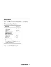
- thinkpad 600 specs
- thinkpad 600e error codes
- thinkpad 600 sound
- thinkpad 600 series
- thinkpad 600 resolution
- thinkpad 600 ram
- thinkpad 600 parts
- thinkpad 600 memory
- thinkpad 600 manual
- thinkpad 600 linux
- thinkpad 600 keyboard
- thinkpad 600 internal cmos battery
- thinkpad 600 install wifi windows xp
- thinkpad 600x drivers
- thinkpad600 windows7
- thinkpad600 windows2000
- thinkpad600 ssd
- thinkpad600 linux
- thinkpad600 hdd
- thinkpad600 bios
- thinkpad600 192
- thinkpad under 600
- thinkpad t 600
- thinkpad 600x notebook
- thinkpad 600x hard drive removal
- thinkpad 600 has black screen
- thinkpad 600x bios setup
- thinkpad 600x bios
- thinkpad 600x battery
- thinkpad 600x
- thinkpad 600e user's guide
- thinkpad 600e user manual
- thinkpad 600e upgrades
- thinkpad 600e specifications
- thinkpad 600e memory
- thinkpad 600e manual
- thinkpad 600e ide controller driver
- lenovo thinkpad 600e
- thinkpad 500gb
- thinkpad 500
- thinkpad 400
- lenovo thinkpad under 600
- lenovo thinkpad t 600
- lenovo thinkpad 600x notebook
- lenovo thinkpad 600x drivers
- lenovo thinkpad 600x
- lenovo thinkpad 600e manual
- lenovo thinkpad 600e drivers
- lenovo thinkpad 600e 2645
- thinkpad 600
- lenovo thinkpad 600
- lenovo thinkpad 500gb
- lenovo thinkpad 500
- lenovo thinkpad 400
- ibm/lenovo thinkpad 600e
- ibm/ thinkpad 600e
- ibm thinkpad 600e
- ibm thinkpad 600 laptop computer
- ibm thinkpad 600
- ibm lenovo thinkpad 600e
- ibm lenovo thinkpad 600 laptop computer
- thinkpad 600 cmos battery
- thinkpad 600 hard drive removal
- thinkpad 600 hard drive
- thinkpad 600 error codes
- thinkpad 600 error 8611
- thinkpad 600 error 192
- thinkpad 600 error 173 192 163
- thinkpad 600 error
- thinkpad 600 enter bios
- thinkpad 600 drivers
- thinkpad 600 driver downloads
- thinkpad 600 cmos battery location
- ibm lenovo thinkpad 600
- thinkpad 600 boot from cd
- thinkpad 600 boot
- thinkpad 600 bios update
- thinkpad 600 bios setup
- thinkpad 600 bios enter
- thinkpad 600 bios battery
- thinkpad 600 bios
- thinkpad 600 battery
- thinkpad 600 backup battery
- thinkpad 600 2645