Hardware Maintenance Manual
Page 5
...Using passwords 39 Password considerations 39 Power-On Password 40 Privileged Access Password 40 Setting, changing, and deleting a password . 40 © Copyright Lenovo 2008, 2011 Enabling or disabling a device 40 Selecting a startup device 41 Selecting a temporary startup device . . . . 41 Selecting or... POST error codes 62 Miscellaneous error messages 63 Undetermined problems 65 Chapter 8. Diagnostics 35 Lenovo System Toolbox 35 PC-Doctor for Windows PE 35 Running diagnostics from the Rescue and Recovery workspace 35 PC-Doctor for DOS 36 Creating a diagnostic CD/DVD image . . ...
...Using passwords 39 Password considerations 39 Power-On Password 40 Privileged Access Password 40 Setting, changing, and deleting a password . 40 © Copyright Lenovo 2008, 2011 Enabling or disabling a device 40 Selecting a startup device 41 Selecting a temporary startup device . . . . 41 Selecting or... POST error codes 62 Miscellaneous error messages 63 Undetermined problems 65 Chapter 8. Diagnostics 35 Lenovo System Toolbox 35 PC-Doctor for Windows PE 35 Running diagnostics from the Rescue and Recovery workspace 35 PC-Doctor for DOS 36 Creating a diagnostic CD/DVD image . . ...
Hardware Maintenance Manual
Page 6
... 7304, 7307,7413, 7491, and 7508 . . . . 121 Mechanical FRUs 147 Keyboard and Mouse 158 Adapters and miscellaneous FRUs 201 Power Cords 209 Recovery discs 221 Overall: MT 7259, 7267, 7269, 7279, 7297, 7303, 7306, 7487, 7506, and 7514 317 Mechanical FRUs 347 Keyboard and Mouse 359 ...Adapters and miscellaneous FRUs 401 Power Cords 410 Recovery discs 422 Chapter 11. Notices 525 Television output notice 526 Trademarks 526 Index 527 iv ThinkCentre Hardware Maintenance Manual 7303, 7306, 7408, 7487, 7506 and 7514 97 Locations 97 Rear...
... 7304, 7307,7413, 7491, and 7508 . . . . 121 Mechanical FRUs 147 Keyboard and Mouse 158 Adapters and miscellaneous FRUs 201 Power Cords 209 Recovery discs 221 Overall: MT 7259, 7267, 7269, 7279, 7297, 7303, 7306, 7487, 7506, and 7514 317 Mechanical FRUs 347 Keyboard and Mouse 359 ...Adapters and miscellaneous FRUs 401 Power Cords 410 Recovery discs 422 Chapter 11. Notices 525 Television output notice 526 Trademarks 526 Index 527 iv ThinkCentre Hardware Maintenance Manual 7303, 7306, 7408, 7487, 7506 and 7514 97 Locations 97 Rear...

Hardware Maintenance Manual
Page 41
...PE The PC-Doctor for Windows PE diagnostic program is part of the Lenovo System Toolbox and PC-Doctor for DOS diagnostic programs from the Rescue and Recovery workspace You can cause hardware failures. The Rescue and Recovery workspace opens. 4. To run the PC-Doctor for additional help. ... created by both diagnostic programs. You will need the log files when you to a Lenovo technical support representative. Press the F1 key for Windows PE diagnostic program from the Rescue and Recovery workspace, do the following: 1. There are unable to isolate and repair the problem yourself...
...PE The PC-Doctor for Windows PE diagnostic program is part of the Lenovo System Toolbox and PC-Doctor for DOS diagnostic programs from the Rescue and Recovery workspace You can cause hardware failures. The Rescue and Recovery workspace opens. 4. To run the PC-Doctor for additional help. ... created by both diagnostic programs. You will need the log files when you to a Lenovo technical support representative. Press the F1 key for Windows PE diagnostic program from the Rescue and Recovery workspace, do the following: 1. There are unable to isolate and repair the problem yourself...
Hardware Maintenance Manual
Page 46
... Setup Utility program menu and select Exit ® Save Changes and Exit. Select the desired devices and settings and press Enter. 40 ThinkCentre Hardware Maintenance Manual After you try to Disabled, the diskette drive cannot be accessed. Start the Setup Utility program. See Chapter 6 "Diagnostics,... Test and Recovery Information" on page 39. 1. See "Starting the Setup Utility program" on how to enable or disable user access to the SATA controller ...
... Setup Utility program menu and select Exit ® Save Changes and Exit. Select the desired devices and settings and press Enter. 40 ThinkCentre Hardware Maintenance Manual After you try to Disabled, the diskette drive cannot be accessed. Start the Setup Utility program. See Chapter 6 "Diagnostics,... Test and Recovery Information" on page 39. 1. See "Starting the Setup Utility program" on how to enable or disable user access to the SATA controller ...
Hardware Maintenance Manual
Page 51
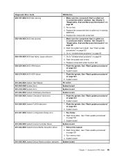
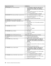
... Index 45 System board No action System board System board System board 1. System board System board Chapter 7. Flash the system. See Chapter 6 "Diagnostics, Test and Recovery Information" on page 39 2. Make sure the component that is called out is connected and/or enabled. See Chapter 6 "Diagnostics, Test and...
... Index 45 System board No action System board System board System board 1. System board System board Chapter 7. Flash the system. See Chapter 6 "Diagnostics, Test and Recovery Information" on page 39 2. Make sure the component that is called out is connected and/or enabled. See Chapter 6 "Diagnostics, Test and...
Hardware Maintenance Manual
Page 52
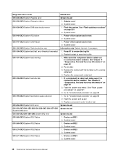
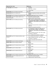
... board 1. Re-run test 3. Flash the system and retest. Go to "Undetermined problems" on page 39 2. See Chapter 6 "Diagnostics, Test and Recovery Information" on page 65 1. Go to "Undetermined problems" on page 521 2. Device on IRQ2 2. Device on IRQ1 2. System board 1. System board..., if necessary 1. Restart the test to review the log file 2. See Chapter 6 "Diagnostics, Test and Recovery Information" on system and re-test 2. System board 46 ThinkCentre Hardware Maintenance Manual System board 1. See "Flash update procedures" on IRQ3 2. Device on page 521 3. Device...
... board 1. Re-run test 3. Flash the system and retest. Go to "Undetermined problems" on page 39 2. See Chapter 6 "Diagnostics, Test and Recovery Information" on page 65 1. Go to "Undetermined problems" on page 521 2. Device on IRQ2 2. Device on IRQ1 2. System board 1. System board..., if necessary 1. Restart the test to review the log file 2. See Chapter 6 "Diagnostics, Test and Recovery Information" on system and re-test 2. System board 46 ThinkCentre Hardware Maintenance Manual System board 1. See "Flash update procedures" on IRQ3 2. Device on page 521 3. Device...
Hardware Maintenance Manual
Page 54
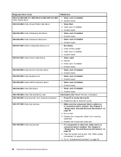
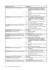
...board 1. Run Setup 2. Video card, if installed 4. Video card, if installed 2. See Chapter 6 "Diagnostics, Test and Recovery Information" on page 521 3. If a component is called out is connected and/or enabled. Video card, if installed 2. System... the test to review the log file 2. System board 1. Video card, if installed 4. See Chapter 6 "Diagnostics, Test and Recovery Information" on page 65 48 ThinkCentre Hardware Maintenance Manual Video card, if installed 3. System board Information only Restart the test, if necessary 1. Video card, if installed ...
...board 1. Run Setup 2. Video card, if installed 4. Video card, if installed 2. See Chapter 6 "Diagnostics, Test and Recovery Information" on page 521 3. If a component is called out is connected and/or enabled. Video card, if installed 2. System... the test to review the log file 2. System board 1. Video card, if installed 4. See Chapter 6 "Diagnostics, Test and Recovery Information" on page 65 48 ThinkCentre Hardware Maintenance Manual Video card, if installed 3. System board Information only Restart the test, if necessary 1. Video card, if installed ...

Hardware Maintenance Manual
Page 56
... out is connected and/or enabled. External serial device 2. System board System board Information only Restart the test, if necessary 50 ThinkCentre Hardware Maintenance Manual Run Setup, enable port 2. Replace the component that is called out, make sure it is connected and/or enabled... board 1. See "Flash update procedures" on page 521 3. See "Flash update procedures" on page 521 3. See Chapter 6 "Diagnostics, Test and Recovery Information" on page 521 3. Go to reset the log file 1. Wrap plug 2. Flash the system. Restart the test to "Undetermined problems" on page...
... out is connected and/or enabled. External serial device 2. System board System board Information only Restart the test, if necessary 50 ThinkCentre Hardware Maintenance Manual Run Setup, enable port 2. Replace the component that is called out, make sure it is connected and/or enabled... board 1. See "Flash update procedures" on page 521 3. See "Flash update procedures" on page 521 3. See Chapter 6 "Diagnostics, Test and Recovery Information" on page 521 3. Go to reset the log file 1. Wrap plug 2. Flash the system. Restart the test to "Undetermined problems" on page...
Hardware Maintenance Manual
Page 57
... "Undetermined problems" on page 39 2. Remove USB device(s) and re-test 2. Run memory test 4. Remove USB device(s) and re-test 2. See Chapter 6 "Diagnostics, Test and Recovery Information" on page 65 1. System board No action 1. Remove USB device(s) and re-test 2. System board 1. System board System board 1. Replace the component that is...
... "Undetermined problems" on page 39 2. Remove USB device(s) and re-test 2. Run memory test 4. Remove USB device(s) and re-test 2. See Chapter 6 "Diagnostics, Test and Recovery Information" on page 65 1. System board No action 1. Remove USB device(s) and re-test 2. System board 1. System board System board 1. Replace the component that is...
Hardware Maintenance Manual
Page 58
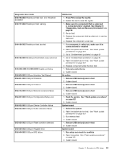
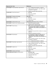
...on page 521 3. See "Flash update procedures" on page 521 3. PCI card 2. See Chapter 6 "Diagnostics, Test and Recovery Information" on page 65 52 ThinkCentre Hardware Maintenance Manual Go to "Undetermined problems" on page 39 2. Replace the component that is called out in warning statement 4.... See Chapter 6 "Diagnostics, Test and Recovery Information" on page 65 015-199-XXX USB port test failed, ...
...on page 521 3. See "Flash update procedures" on page 521 3. PCI card 2. See Chapter 6 "Diagnostics, Test and Recovery Information" on page 65 52 ThinkCentre Hardware Maintenance Manual Go to "Undetermined problems" on page 39 2. Replace the component that is called out in warning statement 4.... See Chapter 6 "Diagnostics, Test and Recovery Information" on page 65 015-199-XXX USB port test failed, ...
Hardware Maintenance Manual
Page 59
PCI card 2. Riser card, if installed 3. System board Information only Restart the test, if necessary 1. See Chapter 6 "Diagnostics, Test and Recovery Information" on page 39 2. See Chapter 6 "Diagnostics, Test and Recovery Information" on page 39 2. Go to review the log file 2. Flash the system and re-test. System board No action 1. Replace component...
PCI card 2. Riser card, if installed 3. System board Information only Restart the test, if necessary 1. See Chapter 6 "Diagnostics, Test and Recovery Information" on page 39 2. See Chapter 6 "Diagnostics, Test and Recovery Information" on page 39 2. Go to review the log file 2. Flash the system and re-test. System board No action 1. Replace component...
Hardware Maintenance Manual
Page 60
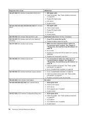
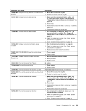
... "Flash update procedures" on page 521 3. Check power supply 3. Re-run test 3. If a component is called out is connected and/or enabled. System board 54 ThinkCentre Hardware Maintenance Manual SCSI device 4. Flash the system. See "Flash update procedures" on page 521 3. Press F3 to reset the log file 1. Flash the system..., if installed 5. SCSI device 4. System board Information only Restart the test, if necessary 1. Reseat IDE signal cable 4. IDE signal cable 2. See Chapter 6 "Diagnostics, Test and Recovery Information" on page 39 2. See Chapter 6 "Diagnostics, Test and...
... "Flash update procedures" on page 521 3. Check power supply 3. Re-run test 3. If a component is called out is connected and/or enabled. System board 54 ThinkCentre Hardware Maintenance Manual SCSI device 4. Flash the system. See "Flash update procedures" on page 521 3. Press F3 to reset the log file 1. Flash the system..., if installed 5. SCSI device 4. System board Information only Restart the test, if necessary 1. Reseat IDE signal cable 4. IDE signal cable 2. See Chapter 6 "Diagnostics, Test and Recovery Information" on page 39 2. See Chapter 6 "Diagnostics, Test and...
Hardware Maintenance Manual
Page 61
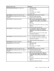
... 5. Go to "Undetermined problems" on page 521 3. See "Flash update procedures" on page 65 1. See Chapter 6 "Diagnostics, Test and Recovery Information" on page 39 2. SCSI signal cable 2. Replace the component that is called out in warning statement 4. Flash the system and re-test... is called out is called out in warning statement 4. SCSI device 4. See Chapter 6 "Diagnostics, Test and Recovery Information" on page 39 2. See Chapter 6 "Diagnostics, Test and Recovery Information" on page 65 2. Go to reset the log file 1. RAID device 3. Restart the test to "...
... 5. Go to "Undetermined problems" on page 521 3. See "Flash update procedures" on page 65 1. See Chapter 6 "Diagnostics, Test and Recovery Information" on page 39 2. SCSI signal cable 2. Replace the component that is called out in warning statement 4. Flash the system and re-test... is called out is called out in warning statement 4. SCSI device 4. See Chapter 6 "Diagnostics, Test and Recovery Information" on page 39 2. See Chapter 6 "Diagnostics, Test and Recovery Information" on page 65 2. Go to reset the log file 1. RAID device 3. Restart the test to "...
Hardware Maintenance Manual
Page 62
...Speakers 2. Audio card, if installed 4. System board Information only Restart the test, if necessary 1. See Chapter 6 "Diagnostics, Test and Recovery Information" on page 521 3. If a component is called out, make sure it is connected and/or enabled. See "Flash update ... See "Flash update procedures" on page 521 3. Run Setup 2. Re-run test 3. Replace the component under function test 56 ThinkCentre Hardware Maintenance Manual Flash the system and re-test. See "Flash update procedures" on page 521 3. See "Undetermined problems" on ...
...Speakers 2. Audio card, if installed 4. System board Information only Restart the test, if necessary 1. See Chapter 6 "Diagnostics, Test and Recovery Information" on page 521 3. If a component is called out, make sure it is connected and/or enabled. See "Flash update ... See "Flash update procedures" on page 521 3. Run Setup 2. Re-run test 3. Replace the component under function test 56 ThinkCentre Hardware Maintenance Manual Flash the system and re-test. See "Flash update procedures" on page 521 3. See "Undetermined problems" on ...
Hardware Maintenance Manual
Page 63
... Information only Restart the test, if necessary 1. Restart the test to review the log file 2. See Chapter 6 "Diagnostics, Test and Recovery Information" on page 39 2. See Chapter 6 "Diagnostics, Test and Recovery Information" on page 39 2. Flash the system and re-test. Mouse 2. Press F3 to reset the log file 1. Press F3 to...
... Information only Restart the test, if necessary 1. Restart the test to review the log file 2. See Chapter 6 "Diagnostics, Test and Recovery Information" on page 39 2. See Chapter 6 "Diagnostics, Test and Recovery Information" on page 39 2. Flash the system and re-test. Mouse 2. Press F3 to reset the log file 1. Press F3 to...
Hardware Maintenance Manual
Page 64
... See "Undetermined problems" on page 39 2. Replace component under test 1. System board Information only Restart the test, if necessary 58 ThinkCentre Hardware Maintenance Manual Replace the component that is connected and/or enabled. Make sure the component that is called out is connected and..." on page 39 2. Press F3 to "Undetermined problems" on page 521 3. Re-run test 3. See Chapter 6 "Diagnostics, Test and Recovery Information" on page 521 3. Make sure the component that is called out is called out in warning statement 4. Replace the component under function test...
... See "Undetermined problems" on page 39 2. Replace component under test 1. System board Information only Restart the test, if necessary 58 ThinkCentre Hardware Maintenance Manual Replace the component that is connected and/or enabled. Make sure the component that is called out is connected and..." on page 39 2. Press F3 to "Undetermined problems" on page 521 3. Re-run test 3. See Chapter 6 "Diagnostics, Test and Recovery Information" on page 521 3. Make sure the component that is called out is called out in warning statement 4. Replace the component under function test...
Hardware Maintenance Manual
Page 65
... Re-run test 3. Replace the component that is called out is called out in warning statement 4. See Chapter 6 "Diagnostics, Test and Recovery Information" on page 521 3. Make sure the component that is connected and/or enabled. Go to reset the log file 1. Restart the ...component is called out, make sure it is connected and/or enabled 2. Symptom-to reset the log file 1. See Chapter 6 "Diagnostics, Test and Recovery Information" on page 39 2. System board 1. Replace the component under test 1. If a component is called out, make sure it is connected and...
... Re-run test 3. Replace the component that is called out is called out in warning statement 4. See Chapter 6 "Diagnostics, Test and Recovery Information" on page 521 3. Make sure the component that is connected and/or enabled. Go to reset the log file 1. Restart the ...component is called out, make sure it is connected and/or enabled 2. Symptom-to reset the log file 1. See Chapter 6 "Diagnostics, Test and Recovery Information" on page 39 2. System board 1. Replace the component under test 1. If a component is called out, make sure it is connected and...
Hardware Maintenance Manual
Page 67
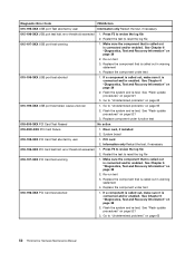
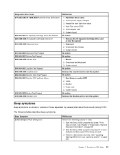
...following tables describes beep symptoms. Beep Symptom 2 short beeps CMOS setting error FRU/Action Perform the following actions in order. 1. Perform a Boot block recovery. System board No action Remove the Joystick and re-test the system No action 1. Run Setup to -FRU Index 61 Chapter 7. Hard Disk ...39. 2. Check power supply voltages 3. Remove the Hi-Capacity Cartridge Drive and re-test the system 1. See Chapter 6 "Diagnostics, Test and Recovery Information" on page 522. Diagnostic Error Code 217-28X-XXX 217-29X-XXX Hard Disk Drive (SCSI) error 220-000-XXX Hi-Capacity Cartridge ...
...following tables describes beep symptoms. Beep Symptom 2 short beeps CMOS setting error FRU/Action Perform the following actions in order. 1. Perform a Boot block recovery. System board No action Remove the Joystick and re-test the system No action 1. Run Setup to -FRU Index 61 Chapter 7. Hard Disk ...39. 2. Check power supply voltages 3. Remove the Hi-Capacity Cartridge Drive and re-test the system 1. See Chapter 6 "Diagnostics, Test and Recovery Information" on page 522. Diagnostic Error Code 217-28X-XXX 217-29X-XXX Hard Disk Drive (SCSI) error 220-000-XXX Hi-Capacity Cartridge ...
Hardware Maintenance Manual
Page 68
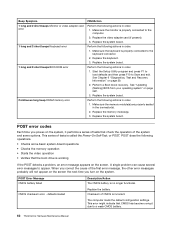
...memory operation • Starts the video operation • Verifies that CMOS has become corrupt due to a weak CMOS battery. 62 ThinkCentre Hardware Maintenance Manual defaults loaded Replace the battery. Checksum of tests is incorrect. Make sure the monitor is no longer functional. Perform...- POST does the following actions in order. 1. See Chapter 6 "Diagnostics, Test and Recovery Information" on page 522. 3. Replace the system board. Replace the system board. Perform a Boot block recovery. POST error codes Each time you turn on the screen. Make sure the keyboard is...
...memory operation • Starts the video operation • Verifies that CMOS has become corrupt due to a weak CMOS battery. 62 ThinkCentre Hardware Maintenance Manual defaults loaded Replace the battery. Checksum of tests is incorrect. Make sure the monitor is no longer functional. Perform...- POST does the following actions in order. 1. See Chapter 6 "Diagnostics, Test and Recovery Information" on page 522. 3. Replace the system board. Replace the system board. Perform a Boot block recovery. POST error codes Each time you turn on the screen. Make sure the keyboard is...
Hardware Maintenance Manual
Page 75
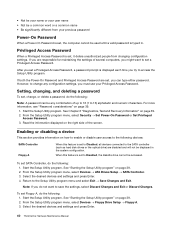
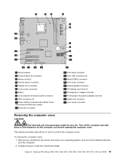
... (2) 4 Thermal sensor connector 5 Diskette drive connector 6 24-pin power connector 7 Battery 8 Cover presence (Intrusion) switch connector 9 SATA connectors (4) 10 Clear CMOS (Complementary Metal Oxide Semiconductor)/Recovery jumper 11 Power fan connector 12 Front panel connector 13 Front USB connectors (2) 14 Serial (COM 2) connector 15 Front audio connector 16 Internal speaker connector...
... (2) 4 Thermal sensor connector 5 Diskette drive connector 6 24-pin power connector 7 Battery 8 Cover presence (Intrusion) switch connector 9 SATA connectors (4) 10 Clear CMOS (Complementary Metal Oxide Semiconductor)/Recovery jumper 11 Power fan connector 12 Front panel connector 13 Front USB connectors (2) 14 Serial (COM 2) connector 15 Front audio connector 16 Internal speaker connector...


