User Manual
Page 5
... compliance statement xiii Power supply statement xiii Products with television tuner options installed . . Troubleshooting and diagnostics 55 © Lenovo 2006, 2007. iii Arranging your computer 20 Obtaining device drivers 21 Removing the cover 22 Locating components 23 Accessing system ...board components 24 Identifying parts on the system board . . . . . 25 Installing memory 29 Installing PCI adapters 30 Installing internal drives 31 Drive specifications 32 Installing a drive in bay 1 33 Installing a diskette drive in ...
... compliance statement xiii Power supply statement xiii Products with television tuner options installed . . Troubleshooting and diagnostics 55 © Lenovo 2006, 2007. iii Arranging your computer 20 Obtaining device drivers 21 Removing the cover 22 Locating components 23 Accessing system ...board components 24 Identifying parts on the system board . . . . . 25 Installing memory 29 Installing PCI adapters 30 Installing internal drives 31 Drive specifications 32 Installing a drive in bay 1 33 Installing a diskette drive in ...

User Manual
Page 9
.... When you handle options or CRUs, or perform any CRUs, turn off the computer and wait three to five minutes to the part. Handle adapters, memory modules, and other body parts away. v Do not place the part on it down.
.... When you handle options or CRUs, or perform any CRUs, turn off the computer and wait three to five minutes to the part. Handle adapters, memory modules, and other body parts away. v Do not place the part on it down.
User Manual
Page 33
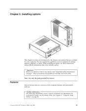
...System information The following information covers a variety of your specific model, use these instructions along with the instructions that are available for your computer by Lenovo. You can expand the capabilities of models. Important Before you work safely. This section provides an overview of the computer features and preinstalled software..... See Chapter 5, "Using the Setup Utility," on page v. Portions © IBM Corp. 2005. 13 Chapter 3. Note: Use only the parts provided by adding memory, adapters, or drives. When installing an option, use the Setup Utility.
...System information The following information covers a variety of your specific model, use these instructions along with the instructions that are available for your computer by Lenovo. You can expand the capabilities of models. Important Before you work safely. This section provides an overview of the computer features and preinstalled software..... See Chapter 5, "Using the Setup Utility," on page v. Portions © IBM Corp. 2005. 13 Chapter 3. Note: Use only the parts provided by adding memory, adapters, or drives. When installing an option, use the Setup Utility.
User Manual
Page 34
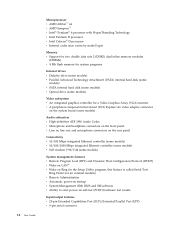
...; 4 processor with HyperThreading Technology v Intel Pentium D processor v Intel Celeron® D processor v Internal cache (size varies by model type) Memory v Support for two double data rate 2 (DDR2) dual inline memory modules (DIMMs) v 4 Mb flash memory for system programs Internal drives v Diskette drive (some models) v Parallel Advanced Technology Attachment (PATA) internal hard disk (some models...
...; 4 processor with HyperThreading Technology v Intel Pentium D processor v Intel Celeron® D processor v Internal cache (size varies by model type) Memory v Support for two double data rate 2 (DDR2) dual inline memory modules (DIMMs) v 4 Mb flash memory for system programs Internal drives v Diskette drive (some models) v Parallel Advanced Technology Attachment (PATA) internal hard disk (some models...

User Manual
Page 36
... drives (some available options: v External options - USB devices, such as a padlock - Monitors v Internal options - System memory, called dual inline memory modules (DIMMs) - Peripheral component interconnect (PCI) adapters - Parallel port devices, such as external modems and digital cameras - Additional...Serial port devices, such as printers and external drives - Operating systems, certified or tested for compatibility1 (varies by Lenovo as compatible with your reseller or marketing representative. 1. Audio devices, such as external speakers for compatibility, check ...
... drives (some available options: v External options - USB devices, such as a padlock - Monitors v Internal options - System memory, called dual inline memory modules (DIMMs) - Peripheral component interconnect (PCI) adapters - Parallel port devices, such as external modems and digital cameras - Additional...Serial port devices, such as printers and external drives - Operating systems, certified or tested for compatibility1 (varies by Lenovo as compatible with your reseller or marketing representative. 1. Audio devices, such as external speakers for compatibility, check ...

User Manual
Page 38
... a flat-blade or Phillips screwdriver. Movement can seriously damage computer components and options. Never touch any type of the positions as a monitor. Handle adapters and memory modules by the edges. v Prevent others from touching components. 18 User Guide When you , can cause static electricity to build up around you might be...
... a flat-blade or Phillips screwdriver. Movement can seriously damage computer components and options. Never touch any type of the positions as a monitor. Handle adapters and memory modules by the edges. v Prevent others from touching components. 18 User Guide When you , can cause static electricity to build up around you might be...

User Manual
Page 43
Locating components The following illustration will help you locate the various components in your computer. 1 Optical drive 2 Diskette drive 3 Memory modules 4 Battery 5 Power supply 6 PCI adapter connector 7 PCI Express x16 graphics adapter or PCI Express x1 adapter connector (some models) 8 PCI Express x1 adapter connector or PCI Express x16 graphics adapter (some models) Chapter 3. Installing options 23
Locating components The following illustration will help you locate the various components in your computer. 1 Optical drive 2 Diskette drive 3 Memory modules 4 Battery 5 Power supply 6 PCI adapter connector 7 PCI Express x16 graphics adapter or PCI Express x1 adapter connector (some models) 8 PCI Express x1 adapter connector or PCI Express x16 graphics adapter (some models) Chapter 3. Installing options 23

User Manual
Page 44
See "Removing the cover" on page 22. 2. Accessing system board components You might have to remove the PCI adapter in order to gain access to the battery. 24 User Guide Remove the front bezel by releasing the three tabs and pivoting the bezel forward to access system board components such as memory, the battery, and CMOS. In some models, you might need to remove the drive bay assembly to remove completely. 3. To access system board components and the drives: 1. Remove the computer cover.
See "Removing the cover" on page 22. 2. Accessing system board components You might have to remove the PCI adapter in order to gain access to the battery. 24 User Guide Remove the front bezel by releasing the three tabs and pivoting the bezel forward to access system board components such as memory, the battery, and CMOS. In some models, you might need to remove the drive bay assembly to remove completely. 3. To access system board components and the drives: 1. Remove the computer cover.

User Manual
Page 46
... on the system board for some computer models. 1 Microprocessor fan connector 12 Front panel connector 2 Microprocessor and heat sink 13 SATA IDE connectors (2) 3 Memory connector 1 14 Front USB connectors (2) 4 Memory connector 2 15 Serial (COM) connector 5 Clear CMOS/Recovery jumper 16 PCI adapter connectors 6 Power connector 17 Front audio connector 7 Diskette drive connector...
... on the system board for some computer models. 1 Microprocessor fan connector 12 Front panel connector 2 Microprocessor and heat sink 13 SATA IDE connectors (2) 3 Memory connector 1 14 Front USB connectors (2) 4 Memory connector 2 15 Serial (COM) connector 5 Clear CMOS/Recovery jumper 16 PCI adapter connectors 6 Power connector 17 Front audio connector 7 Diskette drive connector...

User Manual
Page 47
... the system board for some computer models. 1 Microprocessor and heat sink 12 Front USB connectors (2) 2 Microprocessor fan connector 13 Serial (COM) connector 3 Memory connector 1 14 Front audio connector 4 Memory connector 2 15 CD-IN connector 5 Power connector 16 PCI adapter connectors (2) 6 Diskette drive connector 17 PCI Express x1 adapter connector 7 IDE connector 18...
... the system board for some computer models. 1 Microprocessor and heat sink 12 Front USB connectors (2) 2 Microprocessor fan connector 13 Serial (COM) connector 3 Memory connector 1 14 Front audio connector 4 Memory connector 2 15 CD-IN connector 5 Power connector 16 PCI adapter connectors (2) 6 Diskette drive connector 17 PCI Express x1 adapter connector 7 IDE connector 18...

User Manual
Page 48
The following illustration shows the locations of parts on the system board for some computer models. 1 Microprocessor and heat sink 2 Microprocessor fan connector 3 Memory connector 1 4 Memory connector 2 5 Diskette drive connector 6 Power connector 7 IDE connector 1 8 IDE connector 2 9 Power fan connector 10 SATA IDE connectors (2) 11 Clear CMOS/Recovery jumper 12 Front panel ...
The following illustration shows the locations of parts on the system board for some computer models. 1 Microprocessor and heat sink 2 Microprocessor fan connector 3 Memory connector 1 4 Memory connector 2 5 Diskette drive connector 6 Power connector 7 IDE connector 1 8 IDE connector 2 9 Power fan connector 10 SATA IDE connectors (2) 11 Clear CMOS/Recovery jumper 12 Front panel ...

User Manual
Page 49
...assembly to access the memory connectors. Open the retaining clips. 6. To install a memory module: 1. See "Removing the cover" on the system board. Position the memory module over the memory connector. Locate the memory connectors. Make sure that the notch 1 on the memory module aligns correctly with... the connector key 2 on page 22. 2. Push the memory module straight down into the connector until the ...
...assembly to access the memory connectors. Open the retaining clips. 6. To install a memory module: 1. See "Removing the cover" on the system board. Position the memory module over the memory connector. Locate the memory connectors. Make sure that the notch 1 on the memory module aligns correctly with... the connector key 2 on page 22. 2. Push the memory module straight down into the connector until the ...

User Manual
Page 57
... computer is equipped with another option, go to "Replacing the cover and connecting the cables" on page xii for information about replacing and disposing of memory that the cover cannot be removed when a padlock is displayed when you turn on the computer. An error message is installed.
... computer is equipped with another option, go to "Replacing the cover and connecting the cables" on page xii for information about replacing and disposing of memory that the cover cannot be removed when a padlock is displayed when you turn on the computer. An error message is installed.
User Manual
Page 69
... displayed until you are available: v User Password v Administrator Password You do the following rules: © Lenovo 2006, 2007. If your password. If you can be easily compromised. The Setup Utility might override any passwords, read -only memory (EEPROM) of up to the following : 1. Using passwords By using the Setup Utility program, you...
... displayed until you are available: v User Password v Administrator Password You do the following rules: © Lenovo 2006, 2007. If your password. If you can be easily compromised. The Setup Utility might override any passwords, read -only memory (EEPROM) of up to the following : 1. Using passwords By using the Setup Utility program, you...
User Manual
Page 73
...Updating (flashing) BIOS from a diskette To update (flash) the BIOS from a POST/BIOS update failure. System program updates are available as flash memory). Using system programs System programs are available in a .txt file that is included with the update files. Your computer system board has a ...module called electrically erasable programmable read-only memory (EEPROM, also referred to as downloadable files on the Lenovo Web site at http://www.lenovo.com/support on the screen to the POST/BIOS. When updates are released, they are...
...Updating (flashing) BIOS from a diskette To update (flash) the BIOS from a POST/BIOS update failure. System program updates are available as flash memory). Using system programs System programs are available in a .txt file that is included with the update files. Your computer system board has a ...module called electrically erasable programmable read-only memory (EEPROM, also referred to as downloadable files on the Lenovo Web site at http://www.lenovo.com/support on the screen to the POST/BIOS. When updates are released, they are...

User Manual
Page 85
...with AT and end with ENTER. 0 - 9, A-D, # and * last number redial pulse dialing Note: Pulse dialing is in the modem non-volatile memory. If you dial a number and establish a connection. touch-tone dialing wait for second dial tone pause wait for Australia, New Zealand, Norway, and ...following section lists commands for manually programming your modem from Data Mode to your modem. Command) Force modem on-hook (hang up) © Lenovo 2006, 2007. Commands can be typed in bold text. Switch from a PC running communication software or any other terminal devices. Appendix A. ...
...with AT and end with ENTER. 0 - 9, A-D, # and * last number redial pulse dialing Note: Pulse dialing is in the modem non-volatile memory. If you dial a number and establish a connection. touch-tone dialing wait for second dial tone pause wait for Australia, New Zealand, Norway, and ...following section lists commands for manually programming your modem from Data Mode to your modem. Command) Force modem on-hook (hang up) © Lenovo 2006, 2007. Commands can be typed in bold text. Switch from a PC running communication software or any other terminal devices. Appendix A. ...

User Manual
Page 86
... Guide Function Force modem off-hook (make busy) Note: H1 command is not supported for Italy Display product-identification code Factory ROM checksum test Internal memory test Firmware ID Reserved ID Low speaker volume Low speaker volume Medium speaker volume High speaker volume Internal speaker off Internal speaker on until carrier...
... Guide Function Force modem off-hook (make busy) Note: H1 command is not supported for Italy Display product-identification code Factory ROM checksum test Internal memory test Firmware ID Reserved ID Low speaker volume Low speaker volume Medium speaker volume High speaker volume Internal speaker off Internal speaker on until carrier...
User Manual
Page 95
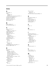
drives (continued) internal 31 specifications 32 dual inline memory modules (DIMMs) 29 E environment, operating 17 Ethernet 14 Ethernet connector 21 exiting, Setup Utility 52 expansion adapters 15 external options 19 F features 13 H help and ... input/output (I/O) features 14 installing operating system 11 software 10 installing options adapters 30 internal drives 31 memory modules 29 security features 35 internal drives 14 K keyboard connector 21 L Lenovo Web site 62 locating components 23 M memory installing 29 modem commands Basic AT 65 Extended AT 67 Fax Class 1 69 Fax Class 2 69...
drives (continued) internal 31 specifications 32 dual inline memory modules (DIMMs) 29 E environment, operating 17 Ethernet 14 Ethernet connector 21 exiting, Setup Utility 52 expansion adapters 15 external options 19 F features 13 H help and ... input/output (I/O) features 14 installing operating system 11 software 10 installing options adapters 30 internal drives 31 memory modules 29 security features 35 internal drives 14 K keyboard connector 21 L Lenovo Web site 62 locating components 23 M memory installing 29 modem commands Basic AT 65 Extended AT 67 Fax Class 1 69 Fax Class 2 69...
User Manual
Page 96
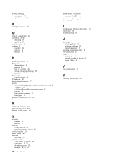
... 49 software installing 10 system board components, accessing 24 connectors 26, 27 identifying parts 25 location 26, 27, 28 76 User Guide system board (continued) memory 16, 29 system management 14 system programs 53 T ThinkVantage Productivity Center 61 trademarks 74 troubleshooting 55 U updating (flashing) BIOS 53 antivirus software 11 operating system...
... 49 software installing 10 system board components, accessing 24 connectors 26, 27 identifying parts 25 location 26, 27, 28 76 User Guide system board (continued) memory 16, 29 system management 14 system programs 53 T ThinkVantage Productivity Center 61 trademarks 74 troubleshooting 55 U updating (flashing) BIOS 53 antivirus software 11 operating system...
(English) Rescue and Recovery 4.3 Deployment Guide
Page 14
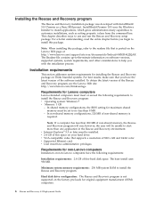
...less than 200 MB of free space on the factory pre-loads for Lenovo computers Lenovo-branded computers must be set to install the Rescue and Recovery program: v Operating system: Windows 7 v Memory: 1 GB - Minimum system memory requirements: 256 MB system RAM to use and run ; v VGA...InstallShield 10.5 Premier as setting property values from the command line. In non-shared memory configurations, 120 MB of the Rescue and Recovery program, see the Lenovo Web site: http://www.lenovo.com/thinkvantage Requirements for original equipment manufacturer (OEM) computers. 6 Rescue and Recovery ...
...less than 200 MB of free space on the factory pre-loads for Lenovo computers Lenovo-branded computers must be set to install the Rescue and Recovery program: v Operating system: Windows 7 v Memory: 1 GB - Minimum system memory requirements: 256 MB system RAM to use and run ; v VGA...InstallShield 10.5 Premier as setting property values from the command line. In non-shared memory configurations, 120 MB of the Rescue and Recovery program, see the Lenovo Web site: http://www.lenovo.com/thinkvantage Requirements for original equipment manufacturer (OEM) computers. 6 Rescue and Recovery ...


