
User Manual
Page 5
Notices 47 Television output notice 48 Trademarks 48 Index 49 © Lenovo 2006. v General safety guidelines vi Service vi Power cords and power adapters vii Extension cords and related devices . . . . . Manual modem commands 39... of your computer 8 Obtaining device drivers 10 Removing the cover 10 Locating components 11 Identifying parts on the system board . . . . . 11 Installing memory 15 Installing adapters 17 Installing internal drives 18 Drive specifications 19 Installing a drive 20 Installing security features 25 Padlock loop 26 Password protection 26 Changing...
Notices 47 Television output notice 48 Trademarks 48 Index 49 © Lenovo 2006. v General safety guidelines vi Service vi Power cords and power adapters vii Extension cords and related devices . . . . . Manual modem commands 39... of your computer 8 Obtaining device drivers 10 Removing the cover 10 Locating components 11 Identifying parts on the system board . . . . . 11 Installing memory 15 Installing adapters 17 Installing internal drives 18 Drive specifications 19 Installing a drive 20 Installing security features 25 Padlock loop 26 Password protection 26 Changing...

User Manual
Page 17
...Installing options Features This chapter provides an introduction to the features and options that come with the instructions that are available for your computer by Lenovo. System information The following information covers a variety of your computer. This section provides an overview of the computer features and preinstalled software. ...Portions © IBM Corp. 2006. 1 Important Before you work safely. Note: Use only the parts provided by adding memory, drives, or adapters. See Chapter 2, "Using the Setup Utility program," on page v.
...Installing options Features This chapter provides an introduction to the features and options that come with the instructions that are available for your computer by Lenovo. System information The following information covers a variety of your computer. This section provides an overview of the computer features and preinstalled software. ...Portions © IBM Corp. 2006. 1 Important Before you work safely. Note: Use only the parts provided by adding memory, drives, or adapters. See Chapter 2, "Using the Setup Utility program," on page v.

User Manual
Page 18
...® D processor v AMD Athlon 64 v AMD Sempron v Internal cache (size varies by model type) Memory v Support for two double data rate (DDR) dual inline memory modules (DIMMs) (some models) v Support for four DDR2 DIMMs (some models) v 4 Mb flash memory Internal drives v Internal Parallel ATA hard disk drive (some models) v Internal Serial ATA hard...
...® D processor v AMD Athlon 64 v AMD Sempron v Internal cache (size varies by model type) Memory v Support for two double data rate (DDR) dual inline memory modules (DIMMs) (some models) v Support for four DDR2 DIMMs (some models) v 4 Mb flash memory Internal drives v Internal Parallel ATA hard disk drive (some models) v Internal Serial ATA hard...

User Manual
Page 21
Audio devices, such as printers and external drives - System memory, called dual inline memory modules (DIMMs) - Accelerated graphics port (AGP) adapters (some models) - PCI Express x16 expansion connectors (some models) - Parallel port devices... such as : - Serial ATA hard disk drive (some models) - Monitors v Internal options - v Within Canada, call 1-800-426-2968, your Lenovo reseller or Lenovo marketing representative. Tools required To install some available options: v External options - Internal drives, such as printers and scanners - See the instructions that come ...
Audio devices, such as printers and external drives - System memory, called dual inline memory modules (DIMMs) - Accelerated graphics port (AGP) adapters (some models) - PCI Express x16 expansion connectors (some models) - Parallel port devices... such as : - Serial ATA hard disk drive (some models) - Monitors v Internal options - v Within Canada, call 1-800-426-2968, your Lenovo reseller or Lenovo marketing representative. Tools required To install some available options: v External options - Internal drives, such as printers and scanners - See the instructions that come ...

User Manual
Page 22
... identify the required connector, and then use the instructions that come with the option to avoid static electricity damage: v Limit your body. Handle adapters and memory modules by the edges. When adding an external option, use the information in the computer without setting the option down. When you can cause static...
... identify the required connector, and then use the instructions that come with the option to avoid static electricity damage: v Limit your body. Handle adapters and memory modules by the edges. When adding an external option, use the information in the computer without setting the option down. When you can cause static...

User Manual
Page 27
Installing options 11 Chapter 1. Locating components The following illustration will help you can install later. It provides basic computer functions and supports a variety of devices that are factory-installed or that you locate the various components in your computer. 1 Microprocessor and heat sink 2 Memory modules 3 AGP adapter or PCI Express x16 adapter graphics connector (some models) 4 PCI connectors 5 PCI adapter 6 Power supply Identifying parts on the system board The system board (sometimes called the planar or motherboard) is the main circuit board in your computer.
Installing options 11 Chapter 1. Locating components The following illustration will help you can install later. It provides basic computer functions and supports a variety of devices that are factory-installed or that you locate the various components in your computer. 1 Microprocessor and heat sink 2 Memory modules 3 AGP adapter or PCI Express x16 adapter graphics connector (some models) 4 PCI connectors 5 PCI adapter 6 Power supply Identifying parts on the system board The system board (sometimes called the planar or motherboard) is the main circuit board in your computer.

User Manual
Page 28
The following illustration shows the locations of parts on the system board for some models. 1 Microprocessor and heat sink 2 Fan connector 3 Memory connector 1 4 Memory connector 2 5 Memory connector 3 6 Memory connector 4 7 Power connector 8 Diskette drive connector 9 Primary IDE connector 10 Battery 11 Clear CMOS/Recovery jumper Note: This part may be a two-pin header. 12 SATA connectors (4) 13 Front panel connector 14 Front USB connector 15 Front audio connector 16 PCI adapter connectors 17 12v power connector 12 User Guide
The following illustration shows the locations of parts on the system board for some models. 1 Microprocessor and heat sink 2 Fan connector 3 Memory connector 1 4 Memory connector 2 5 Memory connector 3 6 Memory connector 4 7 Power connector 8 Diskette drive connector 9 Primary IDE connector 10 Battery 11 Clear CMOS/Recovery jumper Note: This part may be a two-pin header. 12 SATA connectors (4) 13 Front panel connector 14 Front USB connector 15 Front audio connector 16 PCI adapter connectors 17 12v power connector 12 User Guide

User Manual
Page 29
The following illustration shows the locations of parts on the system board for some models. 1 Microprocessor and heat sink 2 Microprocessor fan connector 3 Memory connector 1 4 Memory connector 2 5 Power connector 6 Diskette drive connector 7 Secondary IDE connector 8 Primary IDE connector 9 Battery 10 SATA connectors (2) 11 Clear CMOS/Recovery jumper 12 Power LED connector 13 Front USB connector 14 Front audio connector 15 PCI adapter connectors 16 AGP adapter connector 17 System fan connector 18 12v power connector Chapter 1. Installing options 13
The following illustration shows the locations of parts on the system board for some models. 1 Microprocessor and heat sink 2 Microprocessor fan connector 3 Memory connector 1 4 Memory connector 2 5 Power connector 6 Diskette drive connector 7 Secondary IDE connector 8 Primary IDE connector 9 Battery 10 SATA connectors (2) 11 Clear CMOS/Recovery jumper 12 Power LED connector 13 Front USB connector 14 Front audio connector 15 PCI adapter connectors 16 AGP adapter connector 17 System fan connector 18 12v power connector Chapter 1. Installing options 13

User Manual
Page 30
The following illustration shows the locations of parts on the system board for some models. 1 Microprocessor and heat sink 2 Microprocessor fan connector 3 Memory connector 1 4 Memory connector 2 5 Power connector 6 Diskette drive connector 7 Primary IDE connector 8 Secondary IDE connector 9 System fan connector 10 SATA connectors (2) (some models) 11 Front panel connector 12 Clear CMOS/Recovery jumper 13 Front USB connectors (2) 14 Battery 15 PCI adapter connectors 16 Front audio connector 17 AGP adapter connector 18 12v power connector 14 User Guide
The following illustration shows the locations of parts on the system board for some models. 1 Microprocessor and heat sink 2 Microprocessor fan connector 3 Memory connector 1 4 Memory connector 2 5 Power connector 6 Diskette drive connector 7 Primary IDE connector 8 Secondary IDE connector 9 System fan connector 10 SATA connectors (2) (some models) 11 Front panel connector 12 Clear CMOS/Recovery jumper 13 Front USB connectors (2) 14 Battery 15 PCI adapter connectors 16 Front audio connector 17 AGP adapter connector 18 12v power connector 14 User Guide

User Manual
Page 31
...). (some models) v Use 1.8 V, 240-pin DDR2 SDRAM. (some models) 20 System fan 21 12v power connector Installing memory Your computer has two or four connectors for installing DIMMs. Each DIMM can be a maximum of 1GB providing up to a maximum... of 2.0 GB or 4.0 GB of parts on the system board for some models. 1 Microprocessor and heat sink 2 Microprocessor fan connector 3 Memory connector 1 4 Memory connector 2 5 Memory connector 3 6 Memory connector 4 7 Power connector 8 IDE connector 9 Diskette drive connector 10 SATA connectors (4) 11 Clear CMOS/Recovery jumper 12 Front panel connector 13...
...). (some models) v Use 1.8 V, 240-pin DDR2 SDRAM. (some models) 20 System fan 21 12v power connector Installing memory Your computer has two or four connectors for installing DIMMs. Each DIMM can be a maximum of 1GB providing up to a maximum... of 2.0 GB or 4.0 GB of parts on the system board for some models. 1 Microprocessor and heat sink 2 Microprocessor fan connector 3 Memory connector 1 4 Memory connector 2 5 Memory connector 3 6 Memory connector 4 7 Power connector 8 IDE connector 9 Diskette drive connector 10 SATA connectors (4) 11 Clear CMOS/Recovery jumper 12 Front panel connector 13...

User Manual
Page 32
... appropriate section. v To complete the installation, go to "Replacing the cover and connecting the cables" on the system board. To install a memory module: 1. Locate the memory connectors. See "Removing the cover" on page 11. 3. See "Identifying parts on the system board" on page 10. 2. Open the... retaining clips. 4. Push the memory module straight down into the connector until the retaining clips close. Position the memory module over the memory connector. Removing the cover. What to do next: v To work with the connector key 2...
... appropriate section. v To complete the installation, go to "Replacing the cover and connecting the cables" on the system board. To install a memory module: 1. Locate the memory connectors. See "Removing the cover" on page 11. 3. See "Identifying parts on the system board" on page 10. 2. Open the... retaining clips. 4. Push the memory module straight down into the connector until the retaining clips close. Position the memory module over the memory connector. Removing the cover. What to do next: v To work with the connector key 2...

User Manual
Page 42
... normal use the Setup Utility program to set a password. v To complete the installation, go to the appropriate section. Password protection To deter unauthorized use of memory that locks the cover to your computer, you are lost. Changing the battery Your computer has a special type of your computer when a padlock is installed...
... normal use the Setup Utility program to set a password. v To complete the installation, go to the appropriate section. Password protection To deter unauthorized use of memory that locks the cover to your computer, you are lost. Changing the battery Your computer has a special type of your computer when a padlock is installed...

User Manual
Page 47
..., press Esc to return to the Setup Utility program menu (you have to view and change the configuration settings of either one, read -only memory (EEPROM) of your changes will not be saved. Press and hold the F1 key then turn off the computer. 2. You do the following ...sections. © Lenovo 2006. If your computer, regardless of which operating system you exit. If a user password or an administrator password has been set either type to...
..., press Esc to return to the Setup Utility program menu (you have to view and change the configuration settings of either one, read -only memory (EEPROM) of your changes will not be saved. Press and hold the F1 key then turn off the computer. 2. You do the following ...sections. © Lenovo 2006. If your computer, regardless of which operating system you exit. If a user password or an administrator password has been set either type to...

User Manual
Page 51
...erasable programmable read-only memory (EEPROM, also referred to recover from a POST/BIOS update failure. Lenovo might make changes and enhancements to complete the update. © Lenovo 2006. Updating (flashing) BIOS from your computer. System program updates are available as flash memory). System programs System ...program. They include the power-on the screen to the system programs. When updates are released, they are available at http://www.lenovo.com/support/ on the World Wide Web. 2. If it is a layer of software that translates instructions from the operating system....
...erasable programmable read-only memory (EEPROM, also referred to recover from a POST/BIOS update failure. Lenovo might make changes and enhancements to complete the update. © Lenovo 2006. Updating (flashing) BIOS from your computer. System program updates are available as flash memory). System programs System ...program. They include the power-on the screen to the system programs. When updates are released, they are available at http://www.lenovo.com/support/ on the World Wide Web. 2. If it is a layer of software that translates instructions from the operating system....

User Manual
Page 55
...command that requires one of 0. If you dial a number and establish a connection. All commands can be typed in the modem non-volatile memory. To make the command line more readable, spaces can be inserted between commands. Example: ATH [ENTER] Basic AT commands In the following section... lists commands for manually programming your modem from Data Mode to your modem. Command) Force modem on-hook (hang up) © Lenovo 2006. Manual modem commands The following listings, all default settings are echoed Escape Characters - Do not precede A/ with AT or follow with...
...command that requires one of 0. If you dial a number and establish a connection. All commands can be typed in the modem non-volatile memory. To make the command line more readable, spaces can be inserted between commands. Example: ATH [ENTER] Basic AT commands In the following section... lists commands for manually programming your modem from Data Mode to your modem. Command) Force modem on-hook (hang up) © Lenovo 2006. Manual modem commands The following listings, all default settings are echoed Escape Characters - Do not precede A/ with AT or follow with...

User Manual
Page 56
... Guide Function Force modem off-hook (make busy) Note: H1 command is not supported for Italy Display product-identification code Factory ROM checksum test Internal memory test Firmware ID Reserved ID Low speaker volume Low speaker volume Medium speaker volume High speaker volume Internal speaker off Internal speaker on until carrier...
... Guide Function Force modem off-hook (make busy) Note: H1 command is not supported for Italy Display product-identification code Factory ROM checksum test Internal memory test Firmware ID Reserved ID Low speaker volume Low speaker volume Medium speaker volume High speaker volume Internal speaker off Internal speaker on until carrier...

User Manual
Page 65
K keyboard connector 8, 9 L locating components 11 M memory dual inline memory modules (DIMMs) 15 installing 15 system 15 memory modules, installing 15 microphone connector 8, 9 modem Basic AT commands 39 Extended AT commands 41 Fax Class 1 commands 43 Fax Class 2 commands 43 MNP/V....hard disk 5 installing 20 internal 2, 18 removable media 18 specifications 19 E environment, operating 4 Ethernet connector 8, 9 I input/output (I/O) features 3 installing options adapters 17 internal drives 20 memory 15 memory modules 15 security features 25 © Lenovo 2006. Portions © IBM Corp. 2006.
K keyboard connector 8, 9 L locating components 11 M memory dual inline memory modules (DIMMs) 15 installing 15 system 15 memory modules, installing 15 microphone connector 8, 9 modem Basic AT commands 39 Extended AT commands 41 Fax Class 1 commands 43 Fax Class 2 commands 43 MNP/V....hard disk 5 installing 20 internal 2, 18 removable media 18 specifications 19 E environment, operating 4 Ethernet connector 8, 9 I input/output (I/O) features 3 installing options adapters 17 internal drives 20 memory 15 memory modules 15 security features 25 © Lenovo 2006. Portions © IBM Corp. 2006.

User Manual
Page 66
system board connectors 12, 13, 14, 15 identifying parts 11 location 12, 13, 14 memory 5, 15 system programs 35 U USB connectors 8, 9 V VGA monitor connector 8 video, subsystem 2 voltage switch 8 50 User Guide
system board connectors 12, 13, 14, 15 identifying parts 11 location 12, 13, 14 memory 5, 15 system programs 35 U USB connectors 8, 9 V VGA monitor connector 8 video, subsystem 2 voltage switch 8 50 User Guide
(English) Rescue and Recovery 4.3 Deployment Guide
Page 14
... InstallShield 10.5 Premier as setting property values from the command line. v VGA-compatible video that is required. v 2.4 GB of non-shared memory is posted on the Lenovo Web page at: http://www.lenovo.com/support/site.wss/document.do?lndocid=MIGR-4Q2QAK The Readme file contains up-to-the-minute information on non...
... InstallShield 10.5 Premier as setting property values from the command line. v VGA-compatible video that is required. v 2.4 GB of non-shared memory is posted on the Lenovo Web page at: http://www.lenovo.com/support/site.wss/document.do?lndocid=MIGR-4Q2QAK The Readme file contains up-to-the-minute information on non...
(English) Rescue and Recovery 4.3 Deployment Guide
Page 15
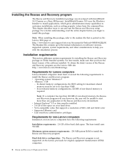
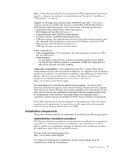
...are included with the Rescue and Recovery software. For information regarding compatibility issues, refer to a specified location. For supported Lenovo computers, required drivers are pre-populated in your OEM. Installation components This section contains installation components of video RAM - ...Installation 7 Installing on OEM systems" on page 54. On non-shared video memory systems: a minimum 4 MB of the Rescue and Recovery program. Application compatibility: Some applications that have complex filter driver environments...
...are included with the Rescue and Recovery software. For information regarding compatibility issues, refer to a specified location. For supported Lenovo computers, required drivers are pre-populated in your OEM. Installation components This section contains installation components of video RAM - ...Installation 7 Installing on OEM systems" on page 54. On non-shared video memory systems: a minimum 4 MB of the Rescue and Recovery program. Application compatibility: Some applications that have complex filter driver environments...


