
User Manual
Page 5
... the connectors on the rear of your computer 8 Obtaining device drivers 10 Removing the cover 10 Locating components 11 Identifying parts on the system board . . . . . 11 Installing memory 15 Installing adapters 17 Installing internal drives 18 Drive specifications 19 Installing a drive 20 Installing security features 25 Padlock loop 26 Password protection 26 Changing the battery 26 Erasing a lost or forgotten password (clearing CMOS 28 Replacing the cover and connecting the cables. . . 29 Chapter 2. Cleaning the mouse . . . 37 Cleaning an optical mouse 37 Cleaning a mouse with...
... the connectors on the rear of your computer 8 Obtaining device drivers 10 Removing the cover 10 Locating components 11 Identifying parts on the system board . . . . . 11 Installing memory 15 Installing adapters 17 Installing internal drives 18 Drive specifications 19 Installing a drive 20 Installing security features 25 Padlock loop 26 Password protection 26 Changing the battery 26 Erasing a lost or forgotten password (clearing CMOS 28 Replacing the cover and connecting the cables. . . 29 Chapter 2. Cleaning the mouse . . . 37 Cleaning an optical mouse 37 Cleaning a mouse with...

User Manual
Page 18
... and headphone connectors on the front panel Connectivity v 10/100 Mbps integrated Ethernet controller that supports the Wake on LAN® feature (some models) v 10/100/1000 Mbps integrated Ethernet controller (some models) v Soft modem V.90/V.44 (some models) System management features v Wake on LAN v Wake on Ring (in the Setup Utility program, this feature is called Serial Port Ring Detect for an external modem) v Remote Administration v Automatic power-on startup v System Management (SM) BIOS and SM software 2 User Guide
... and headphone connectors on the front panel Connectivity v 10/100 Mbps integrated Ethernet controller that supports the Wake on LAN® feature (some models) v 10/100/1000 Mbps integrated Ethernet controller (some models) v Soft modem V.90/V.44 (some models) System management features v Wake on LAN v Wake on Ring (in the Setup Utility program, this feature is called Serial Port Ring Detect for an external modem) v Remote Administration v Automatic power-on startup v System Management (SM) BIOS and SM software 2 User Guide

User Manual
Page 21
... scanners - Chapter 1. Accelerated graphics port (AGP) adapters (some models) - Monitors v Internal options - Parallel ATA hard disk drive (some models) Note: When adding a serial ATA hard disk drive, the drive must support the legency four-pin power connector. Tools required To install some available options: v External options - Installing options 5 Security device, such as external modems and digital cameras - Audio devices, such as external speakers for certain options. Serial ATA hard disk drive (some models) - Serial port devices, such as a padlock loop...
... scanners - Chapter 1. Accelerated graphics port (AGP) adapters (some models) - Monitors v Internal options - Parallel ATA hard disk drive (some models) Note: When adding a serial ATA hard disk drive, the drive must support the legency four-pin power connector. Tools required To install some available options: v External options - Installing options 5 Security device, such as external modems and digital cameras - Audio devices, such as external speakers for certain options. Serial ATA hard disk drive (some models) - Serial port devices, such as a padlock loop...

User Manual
Page 58
...). e=0-1; Command &W_ %E_ +MS? +MS=? +MS=a,b,c,e,f &V1 &W0 &W1 %E0 %E1 Function Display Last Connection Statistics Stores the active profile as Profile 0 Stores the active profile as Profile 1 Disable auto-retrain Enable auto-retrain Displays the current Select Modulation settings Displays a list of support values 42 User Guide b=0-1; c=300-56000; and f=0-1. Parameter ″a″ specifies the modulation protocol desired where: 0=V.21...
...). e=0-1; Command &W_ %E_ +MS? +MS=? +MS=a,b,c,e,f &V1 &W0 &W1 %E0 %E1 Function Display Last Connection Statistics Stores the active profile as Profile 0 Stores the active profile as Profile 1 Disable auto-retrain Enable auto-retrain Displays the current Select Modulation settings Displays a list of support values 42 User Guide b=0-1; c=300-56000; and f=0-1. Parameter ″a″ specifies the modulation protocol desired where: 0=V.21...

User Manual
Page 65
... 2 C cables, connecting 29 changing the battery 26 cleaning the mouse 37 commands Basic AT 39 Extended AT 41 Fax Class 1 43 Fax Class 2 43 MNP/V.42/V.42bis/V.44 42 Voice 44 connector description 9 cover removing 10 replacing 29 D device, drivers 10 drives bays 3, 19 CD 5 DVD 5 hard disk 5 installing 20 internal 2, 18 removable media 18 specifications 19 E environment, operating 4 Ethernet connector 8, 9 I input/output (I/O) features 3 installing options adapters 17 internal drives 20 memory 15 memory modules 15 security features 25 © Lenovo...
... 2 C cables, connecting 29 changing the battery 26 cleaning the mouse 37 commands Basic AT 39 Extended AT 41 Fax Class 1 43 Fax Class 2 43 MNP/V.42/V.42bis/V.44 42 Voice 44 connector description 9 cover removing 10 replacing 29 D device, drivers 10 drives bays 3, 19 CD 5 DVD 5 hard disk 5 installing 20 internal 2, 18 removable media 18 specifications 19 E environment, operating 4 Ethernet connector 8, 9 I input/output (I/O) features 3 installing options adapters 17 internal drives 20 memory 15 memory modules 15 security features 25 © Lenovo...
(English) Rescue and Recovery 4.3 Deployment Guide
Page 5
... the preboot environment . . . . 36 Configuring the Opera browser 41 Changing the video resolution 47 Startup applications 47 Passwords 48 Password access 48 Log files 49 Create Rescue Media 49 Chapter 4. Installing on OEM systems . . . . . 54 Best practices for hard drive setup: Option 1 . . 55 Best practices for hard drive setup: Option 2 . . 55 Scenario 3 - Manually creating the Service Partition of S drive 58 Appendix A. Administrative tools . . . 61 Command line support 61 Mailman 61 AWizard.exe...
... the preboot environment . . . . 36 Configuring the Opera browser 41 Changing the video resolution 47 Startup applications 47 Passwords 48 Password access 48 Log files 49 Create Rescue Media 49 Chapter 4. Installing on OEM systems . . . . . 54 Best practices for hard drive setup: Option 1 . . 55 Best practices for hard drive setup: Option 2 . . 55 Scenario 3 - Manually creating the Service Partition of S drive 58 Appendix A. Administrative tools . . . 61 Command line support 61 Mailman 61 AWizard.exe...
(English) Rescue and Recovery 4.3 Deployment Guide
Page 21
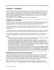
..., the image must use the Microsoft BitLocker Drive Preparation Tool. Refer to prepare the BitLocker partition, you must have two partitions on your operating system is not activated in size. These variables can be type 0x07. For example, to change the c:\Program Files\Lenovo\Rescue and Recovery directory from the Start menu. If you must capture the whole disk and all partitions. When Windows 7 is installed...
..., the image must use the Microsoft BitLocker Drive Preparation Tool. Refer to prepare the BitLocker partition, you must have two partitions on your operating system is not activated in size. These variables can be type 0x07. For example, to change the c:\Program Files\Lenovo\Rescue and Recovery directory from the Start menu. If you must capture the whole disk and all partitions. When Windows 7 is installed...
(English) Rescue and Recovery 4.3 Deployment Guide
Page 30
... file. To install the setup files using the MSIEXE file: a. The NetPath entry is created on the registry settings located at HKLM\Software\Lenovo\MND. Rejuvenating or restoring the operating system and applications will fail. Mapping a network drive for large enterprise that will use the same user name and password. The following : 1. The UNC entry is an example entry for mapping a network drive: UNC=\\server\share NetPath...
... file. To install the setup files using the MSIEXE file: a. The NetPath entry is created on the registry settings located at HKLM\Software\Lenovo\MND. Rejuvenating or restoring the operating system and applications will fail. Mapping a network drive for large enterprise that will use the same user name and password. The following : 1. The UNC entry is an example entry for mapping a network drive: UNC=\\server\share NetPath...
(English) Rescue and Recovery 4.3 Deployment Guide
Page 36
... OS & Apps restore through the registry at the following Active Directory policy: ThinkVantage\Rescue and Recovery\User Interface\Simple User Interface 28 Rescue and Recovery 4.3 Deployment Guide If the Simplified User Interface setting is managed through the registry key settings: HKLM\SOFTWARE\Lenovo\Rescue and Recovery\Settings\OSAppsList The OSAppsList setting will be placed in this external file. This GUI exclude list is disabled, the advanced user interface will define...
... OS & Apps restore through the registry at the following Active Directory policy: ThinkVantage\Rescue and Recovery\User Interface\Simple User Interface 28 Rescue and Recovery 4.3 Deployment Guide If the Simplified User Interface setting is managed through the registry key settings: HKLM\SOFTWARE\Lenovo\Rescue and Recovery\Settings\OSAppsList The OSAppsList setting will be placed in this external file. This GUI exclude list is disabled, the advanced user interface will define...
(English) Rescue and Recovery 4.5 Deployment Guide
Page 3
... CREATSP 56 InvAgent 56 MapDrv 57 Rescue and Recovery Boot manager control (BMGR32 58 BMGR CLEAN 61 Active Directory Support 62 Administrative (ADM) template files . . . . . 62 Group Policy settings 63 Appendix B. New rollouts 45 Preparing the hard disk drive 45 Installing 45 Updating 47 Enabling the Rescue and Recovery desktop . 47 Scenario 2 - Working with WIM files and Windows 7 48 Scenario 3 - Installing with Active Directory and ADM files 49...
... CREATSP 56 InvAgent 56 MapDrv 57 Rescue and Recovery Boot manager control (BMGR32 58 BMGR CLEAN 61 Active Directory Support 62 Administrative (ADM) template files . . . . . 62 Group Policy settings 63 Appendix B. New rollouts 45 Preparing the hard disk drive 45 Installing 45 Updating 47 Enabling the Rescue and Recovery desktop . 47 Scenario 2 - Working with WIM files and Windows 7 48 Scenario 3 - Installing with Active Directory and ADM files 49...
(English) Rescue and Recovery 4.5 Deployment Guide
Page 9
... to locate © Copyright Lenovo 2008, 2011 3 Once the XML file is named rnrdeploy.xml. Both Windows PE and Storage Management Subsystem use and run the Rescue and Recovery setup package. This practice is posted on page 50 for all settings will allow a user to choose the operating system and then gain access to the entire hard drive without needing to customize installations, such as a virtual partition...
... to locate © Copyright Lenovo 2008, 2011 3 Once the XML file is named rnrdeploy.xml. Both Windows PE and Storage Management Subsystem use and run the Rescue and Recovery setup package. This practice is posted on page 50 for all settings will allow a user to choose the operating system and then gain access to the entire hard drive without needing to customize installations, such as a virtual partition...

(English) Rescue and Recovery 4.5 Deployment Guide
Page 27
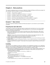
... start "TVT Backup Service" :Create Sysprep Base Backup to Local Hard Drive : Type the following message: ** Ready to take a backup. ** 7. When complete, the message Sysprep Backup is complete. Capture the image for Primary partitions. 3. For all MSI files, add the following command: : Silent install using MSIEXE: a. To silently install the setup files using MSIEXE: With reboot at : HKLM\SOFTWARE\Lenovo\Rescue and Recovery\Settings\BackupList. Power off the system using...
... start "TVT Backup Service" :Create Sysprep Base Backup to Local Hard Drive : Type the following message: ** Ready to take a backup. ** 7. When complete, the message Sysprep Backup is complete. Capture the image for Primary partitions. 3. For all MSI files, add the following command: : Silent install using MSIEXE: a. To silently install the setup files using MSIEXE: With reboot at : HKLM\SOFTWARE\Lenovo\Rescue and Recovery\Settings\BackupList. Power off the system using...

(English) Rescue and Recovery 4.5 Deployment Guide
Page 31
... information through the registry key settings: HKLM\SOFTWARE\Lenovo\Rescue and Recovery\Settings\OSAppsList The OSAppsList setting will see the accompanying XML/ADM Supplement for the deployment guide located on the ThinkVantage Technologies Administrator Tools page: http://support.lenovo.com/en_US/detail.page?LegacyDocID=TVAN-ADMIN#rnr Working with their customization options are stored in a manner which can disable interface switching so that match the...
... information through the registry key settings: HKLM\SOFTWARE\Lenovo\Rescue and Recovery\Settings\OSAppsList The OSAppsList setting will see the accompanying XML/ADM Supplement for the deployment guide located on the ThinkVantage Technologies Administrator Tools page: http://support.lenovo.com/en_US/detail.page?LegacyDocID=TVAN-ADMIN#rnr Working with their customization options are stored in a manner which can disable interface switching so that match the...
(English) Rescue and Recovery 4.5 Deployment Guide
Page 51
... Rescue and Recovery program in the root of the target hard disk drive. Boot the diskette (only one -half. 1. New rollouts" on Lenovo-branded computers. Manually creating the Service Partition of your donor system as second hard disk drives, USB hard disk drives, USB memory keys and PC Card Memory from the target hard disk drive. 2. Create a DOS boot diskette and place the cleandrv.exe file on page 50 Scenario 1 - At the DOS prompt, type the following...
... Rescue and Recovery program in the root of the target hard disk drive. Boot the diskette (only one -half. 1. New rollouts" on Lenovo-branded computers. Manually creating the Service Partition of your donor system as second hard disk drives, USB hard disk drives, USB memory keys and PC Card Memory from the target hard disk drive. 2. Create a DOS boot diskette and place the cleandrv.exe file on page 50 Scenario 1 - At the DOS prompt, type the following...

Hardware Maintenance Manual
Page 5
... Machine types 8290, 8291, 8292, 8469, 8472, 8708, 8709, 8719, 8771, 8772, 8776, 8777, 8817, 9214, 9215, and 9216 103 Machine types 8463, 8464, 8465, 8712, and 8713 107 Replacing the primary hard disk drive . . . . . 112 Replacing an optical drive 113 Replacing the diskette drive 114 Replacing the power switch/ LED assembly . . . 115 Replacing the front panel card 116 Completing the FRU replacement 116 Chapter 9. Symptom-to-FRU Index . . . 53 Hard disk drive boot error 53 Power Supply Problems...
... Machine types 8290, 8291, 8292, 8469, 8472, 8708, 8709, 8719, 8771, 8772, 8776, 8777, 8817, 9214, 9215, and 9216 103 Machine types 8463, 8464, 8465, 8712, and 8713 107 Replacing the primary hard disk drive . . . . . 112 Replacing an optical drive 113 Replacing the diskette drive 114 Replacing the power switch/ LED assembly . . . 115 Replacing the front panel card 116 Completing the FRU replacement 116 Chapter 9. Symptom-to-FRU Index . . . 53 Hard disk drive boot error 53 Power Supply Problems...

Hardware Maintenance Manual
Page 47
... page 55. Set all external devices. 5. Look at step 7. 7. If you select an incorrect drive. v Machine type and model v Processor or hard disk upgrades v Failure symptom - For an explanation of BIOS is installed on page 43. Chapter 4. v If you hear beep codes during write operations such as copying, saving, or formatting. Use the following conditions and follow the instructions: v If you receive an error, replace the part that the diagnostic program calls out...
... page 55. Set all external devices. 5. Look at step 7. 7. If you select an incorrect drive. v Machine type and model v Processor or hard disk upgrades v Failure symptom - For an explanation of BIOS is installed on page 43. Chapter 4. v If you hear beep codes during write operations such as copying, saving, or formatting. Use the following conditions and follow the instructions: v If you receive an error, replace the part that the diagnostic program calls out...
Hardware Maintenance Manual
Page 62
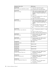
... "Flash update procedures" on page 80 2. Flash the system. Flash the system. Run Setup 2. Re-start the test to review the log file 2. Go to "Undetermined problems" on page 337 2. Flash the system. System board 56 Hardware Maintenance Manual Press F3 to reset the log file 1. Replace component under test 1. System board No action System board System board System board 1. See Chapter 6, "Using the Setup Utility," on page 80 1. See "Flash update procedures" on page 337 3. Make sure...
... "Flash update procedures" on page 80 2. Flash the system. Flash the system. Run Setup 2. Re-start the test to review the log file 2. Go to "Undetermined problems" on page 337 2. Flash the system. System board 56 Hardware Maintenance Manual Press F3 to reset the log file 1. Replace component under test 1. System board No action System board System board System board 1. See Chapter 6, "Using the Setup Utility," on page 80 1. See "Flash update procedures" on page 337 3. Make sure...

Hardware Maintenance Manual
Page 86
... Drive Cable Other display symptoms not listed above (including blank or illegible display) 1. Power switch/LED assembly light not on the keyboard do not work 1. System Board Program loads from the hard disk with a known-good diagnostic diskette. 1. Diskette Drive Cable 4. hard disk 2. External Device 3. System Board Some or all keys on , but computer works correctly 2. a. External devices (modem, printer, or mouse) b. Any adapters 80 Hardware Maintenance Manual Printer 2. System Board 5. network b. External Device 3. Keyboard 2. System Board Undetermined problems...
... Drive Cable Other display symptoms not listed above (including blank or illegible display) 1. Power switch/LED assembly light not on the keyboard do not work 1. System Board Program loads from the hard disk with a known-good diagnostic diskette. 1. Diskette Drive Cable 4. hard disk 2. External Device 3. System Board Some or all keys on , but computer works correctly 2. a. External devices (modem, printer, or mouse) b. Any adapters 80 Hardware Maintenance Manual Printer 2. System Board 5. network b. External Device 3. Keyboard 2. System Board Undetermined problems...

Hardware Maintenance Manual
Page 101
... replacing the system board, a new retention bracket for your machine type at "Identifying parts on the system board" on page 92. 4. See "Removing the covers" on page 86. 8. Replacing FRUs (Tower computers) 95 Lift the power supply out of the chassis. 7. Reconnect all power supply cables to the system board. Remove the left-side cover. Remove the screws that hold the power supply in the PCI connectors. Go to help make the system board more accessible. 3. Replacing...
... replacing the system board, a new retention bracket for your machine type at "Identifying parts on the system board" on page 92. 4. See "Removing the covers" on page 86. 8. Replacing FRUs (Tower computers) 95 Lift the power supply out of the chassis. 7. Reconnect all power supply cables to the system board. Remove the left-side cover. Remove the screws that hold the power supply in the PCI connectors. Go to help make the system board more accessible. 3. Replacing...

Hardware Maintenance Manual
Page 218
... listed in the following table are not illustrated. 212 Hardware Maintenance Manual Lenovo (models) 7 Front panel card (all models) 5 Hard disk drive, 80GB, 7200rpm Serial ATA (models) 5 Hard disk drive, 80GB, 7200rpm Serial ATA (models) 6 Diskette drive, 3.5″ 1.44MB 2 Mode (w/bezel) -- Machine Type 8474 Item # 8474 FRUs 1 Fan Sink - Intel Prescott & Celeron (models) 2 Microprocessor, Pentium 4 630 Processor 3.0 GHz 800 FSB 2MB L2 (models) 3 DVD-ROM 16x -48x (models) 3 DVD-ROM 16x -48x (models) 3 DVD-ROM 16x -48x (models) 4 Power Switch/LED (all models) 8 Memory module...
... listed in the following table are not illustrated. 212 Hardware Maintenance Manual Lenovo (models) 7 Front panel card (all models) 5 Hard disk drive, 80GB, 7200rpm Serial ATA (models) 5 Hard disk drive, 80GB, 7200rpm Serial ATA (models) 6 Diskette drive, 3.5″ 1.44MB 2 Mode (w/bezel) -- Machine Type 8474 Item # 8474 FRUs 1 Fan Sink - Intel Prescott & Celeron (models) 2 Microprocessor, Pentium 4 630 Processor 3.0 GHz 800 FSB 2MB L2 (models) 3 DVD-ROM 16x -48x (models) 3 DVD-ROM 16x -48x (models) 3 DVD-ROM 16x -48x (models) 4 Power Switch/LED (all models) 8 Memory module...


