Hardware Maintenance Manual
Page 5
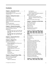
..., 9946, 9953 67 Locating controls and connectors on the front of your computer 67 Rear connectors 67 Removing the cover 68 Locations 69 Locating parts on the system board 71 Removing and replacing the front bezel . . . . . 71 Replacing the power supply 72 Replacing the system .... . . 89 Replacing the power switch/LED assembly . . . 89 Replacing the CMOS battery 90 Completing the FRU replacement 91 Chapter 9. Diagnostics 33 Lenovo System Toolbox 33 PC-Doctor for Windows PE 33 Running diagnostics from the Rescue and Recovery workspace 33 PC-Doctor for DOS 34 Creating a diagnostic...
..., 9946, 9953 67 Locating controls and connectors on the front of your computer 67 Rear connectors 67 Removing the cover 68 Locations 69 Locating parts on the system board 71 Removing and replacing the front bezel . . . . . 71 Replacing the power supply 72 Replacing the system .... . . 89 Replacing the power switch/LED assembly . . . 89 Replacing the CMOS battery 90 Completing the FRU replacement 91 Chapter 9. Diagnostics 33 Lenovo System Toolbox 33 PC-Doctor for Windows PE 33 Running diagnostics from the Rescue and Recovery workspace 33 PC-Doctor for DOS 34 Creating a diagnostic...
Hardware Maintenance Manual
Page 6
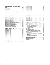
... Automatic Power-On features 468 Appendix A. Notices 471 Television output notice 472 Trademarks 472 vi ThinkCentre Hardware Maintenance Manual 9426, 9486, 9624, 9707, 9787, 9804, 9945 93 Rear connectors 93 Removing the cover 94 Locations 94 Locating parts on the system board 95 Accessing system board components and drives . 96 Replacing a memory...
... Automatic Power-On features 468 Appendix A. Notices 471 Television output notice 472 Trademarks 472 vi ThinkCentre Hardware Maintenance Manual 9426, 9486, 9624, 9707, 9787, 9804, 9945 93 Rear connectors 93 Removing the cover 94 Locations 94 Locating parts on the system board 95 Accessing system board components and drives . 96 Replacing a memory...
Hardware Maintenance Manual
Page 7
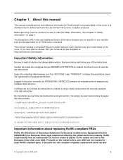
... for trained servicers who are applicable to read the Safety Information. If the parts are also available at: http:/www.lenovo.com/support Important Safety Information Be sure to all ThinkCentre computers. About this book before June 2006 are not required to read all ...market and sold in Electrical and Electronic Equipment Directive (2002/95/EC) is intended only for ThinkCentre® computers listed on the cover. Before servicing a Lenovo product, be implemented on Lenovo products placed on page 3. Products on the market before performing any machine type and are ...
... for trained servicers who are applicable to read the Safety Information. If the parts are also available at: http:/www.lenovo.com/support Important Safety Information Be sure to all ThinkCentre computers. About this book before June 2006 are not required to read all ...market and sold in Electrical and Electronic Equipment Directive (2002/95/EC) is intended only for ThinkCentre® computers listed on the cover. Before servicing a Lenovo product, be implemented on Lenovo products placed on page 3. Products on the market before performing any machine type and are ...
Hardware Maintenance Manual
Page 8
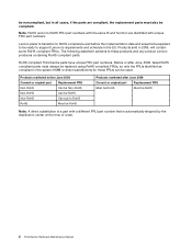
Products marketed before the implementation date and expects its suppliers to these products and any product Lenovo produces containing RoHS compliant parts. RoHS compliant ThinkCentre parts have unique FRU part numbers. Before or after June, 2006, failed RoHS compliant parts must also be ready to RoHS RoHS Must be RoHS Products marketed after June 2006 Current or...
Products marketed before the implementation date and expects its suppliers to these products and any product Lenovo produces containing RoHS compliant parts. RoHS compliant ThinkCentre parts have unique FRU part numbers. Before or after June, 2006, failed RoHS compliant parts must also be ready to RoHS RoHS Must be RoHS Products marketed after June 2006 Current or...
Hardware Maintenance Manual
Page 9
... with before you are : hammering, drilling soldering, cutting wire, attaching springs, using solvents, or working on electrical equipment. © Copyright Lenovo 2008, 2010 3 Observe the following rules when working in any objects that weigh more than 16 kg (35 lb) or objects that you... customer's personnel are fastened or rolled up with a nonconductive clip, approximately 8 centimeters (3 inches) from walk areas so that other parts in the moving parts of your necktie or scarf inside clothing or fasten it . • Do not wear loose clothing that can be hazardous. this...
... with before you are : hammering, drilling soldering, cutting wire, attaching springs, using solvents, or working on electrical equipment. © Copyright Lenovo 2008, 2010 3 Observe the following rules when working in any objects that weigh more than 16 kg (35 lb) or objects that you... customer's personnel are fastened or rolled up with a nonconductive clip, approximately 8 centimeters (3 inches) from walk areas so that other parts in the moving parts of your necktie or scarf inside clothing or fasten it . • Do not wear loose clothing that can be hazardous. this...
Hardware Maintenance Manual
Page 10
... Remember: There must be a complete circuit to work on suitable rubber mats (obtained locally, if necessary) to get medical aid. 4 ThinkCentre Hardware Maintenance Manual Examples of these instructions are in your electrical hand tools for safe operational condition. • Do not use the approved... and test equipment. these hazards are removed from their equipment, rubber floor mats that has exposed electrical circuits, observe the following parts with the power on a machine that contain small conductive fibers to work area. keep the other hand in the off power....
... Remember: There must be a complete circuit to work on suitable rubber mats (obtained locally, if necessary) to get medical aid. 4 ThinkCentre Hardware Maintenance Manual Examples of these instructions are in your electrical hand tools for safe operational condition. • Do not use the approved... and test equipment. these hazards are removed from their equipment, rubber floor mats that has exposed electrical circuits, observe the following parts with the power on a machine that contain small conductive fibers to work area. keep the other hand in the off power....
Hardware Maintenance Manual
Page 11
... near the power-cord connection point on the frame can cause permanent damage to attachment of the voltage provided at the voltage provided in the parts listings. Use a meter to match the voltage available at your local electric company or refer to official Web sites or other literature for 0.1 ohm or...
... near the power-cord connection point on the frame can cause permanent damage to attachment of the voltage provided at the voltage provided in the parts listings. Use a meter to match the voltage available at your local electric company or refer to official Web sites or other literature for 0.1 ohm or...
Hardware Maintenance Manual
Page 12
...in the following languages: • English • Arabic • Brazilian/Portuguese • Chinese (simplified) • Chinese (traditional) 6 ThinkCentre Hardware Maintenance Manual You can occur when there is required for any frame ground, ground braid, or green-wire ground. - Handling electrostatic ...discharge-sensitive devices Any computer part containing transistors or integrated circuits (ICs) should be verified by equalizing the charge so that the power-supply cover fasteners (...
...in the following languages: • English • Arabic • Brazilian/Portuguese • Chinese (simplified) • Chinese (traditional) 6 ThinkCentre Hardware Maintenance Manual You can occur when there is required for any frame ground, ground braid, or green-wire ground. - Handling electrostatic ...discharge-sensitive devices Any computer part containing transistors or integrated circuits (ICs) should be verified by equalizing the charge so that the power-supply cover fasteners (...
Hardware Maintenance Manual
Page 13
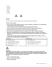
... wired and grounded electrical outlet. • Connect to properly wired outlets any equipment that will be attached to this product. • When possible, use only Part Number 33F8354 or an equivalent type battery recommended by the same manufacturer. If your system has a module containing a lithium battery, replace it only with the...
... wired and grounded electrical outlet. • Connect to properly wired outlets any equipment that will be attached to this product. • When possible, use only Part Number 33F8354 or an equivalent type battery recommended by the same manufacturer. If your system has a module containing a lithium battery, replace it only with the...
Hardware Maintenance Manual
Page 14
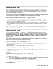
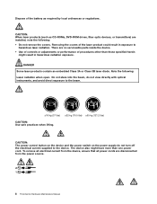
There are disconnected from the power source. 2 1 8 ThinkCentre Hardware Maintenance Manual CAUTION: The power control button on the device and the power switch on the power supply do not view directly with optical ... an embedded Class 3A or Class 3B laser diode. To remove all electrical current from the device, ensure that all power cords are no serviceable parts inside the device. • Use of controls or adjustments or performance of procedures other than one power cord. Do not stare into the beam, do...
There are disconnected from the power source. 2 1 8 ThinkCentre Hardware Maintenance Manual CAUTION: The power control button on the device and the power switch on the power supply do not view directly with optical ... an embedded Class 3A or Class 3B laser diode. To remove all electrical current from the device, ensure that all power cords are no serviceable parts inside the device. • Use of controls or adjustments or performance of procedures other than one power cord. Do not stare into the beam, do...
Hardware Maintenance Manual
Page 35
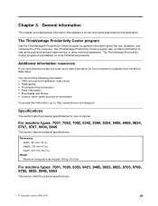
...Publications • Troubleshooting information • Parts information • Downloads and drivers • Links to http://www.lenovo.com/support/. Chapter 3. The ThinkVantage ...Productivity Center program Use the ThinkVantage® Productivity Center program for your computer. General information This chapter provides general information that applies to all machine types supported by this information, go to other technical assistance. Additional information resources If you have Internet access, the most ThinkCentre...
...Publications • Troubleshooting information • Parts information • Downloads and drivers • Links to http://www.lenovo.com/support/. Chapter 3. The ThinkVantage ...Productivity Center program Use the ThinkVantage® Productivity Center program for your computer. General information This chapter provides general information that applies to all machine types supported by this information, go to other technical assistance. Additional information resources If you have Internet access, the most ThinkCentre...
Hardware Maintenance Manual
Page 37
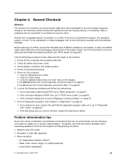
... to step 7 on all external devices. 2. Power-on page 31. 6. Do diagnostics indicate a failure? - Is the failure repeatable? © Copyright Lenovo 2008, 2010 31 Chapter 4. Power-off the computer and all external devices. 5. Power-on the computer. • Look for displayed error codes •...; Processor or hard disk upgrades • Failure symptom - Data or programs can be overwritten if you receive an error, replace the part that software package. For more information on how to "Diagnostic error codes" on page 31. General Checkout Attention The drives in problem...
... to step 7 on all external devices. 2. Power-on page 31. 6. Do diagnostics indicate a failure? - Is the failure repeatable? © Copyright Lenovo 2008, 2010 31 Chapter 4. Power-off the computer and all external devices. 5. Power-on the computer. • Look for displayed error codes •...; Processor or hard disk upgrades • Failure symptom - Data or programs can be overwritten if you receive an error, replace the part that software package. For more information on how to "Diagnostic error codes" on page 31. General Checkout Attention The drives in problem...
Hardware Maintenance Manual
Page 39
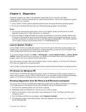
...can cause hardware failures. Use PC-Doctor for Windows has not been successful in C:\PCDR\DETAILED.txt.) Lenovo System Toolbox Lenovo System Toolbox is part of the Lenovo System Toolbox and PC-Doctor for DOS diagnostic programs from the Rescue and Recovery workspace, use the following...after you still suspect a problem after Lenovo System Toolbox runs successfully, run Lenovo System Toolbox, click Start ® All Programs ® Lenovo System Toolbox ® Lenovo System Toolbox. If you want to the Lenovo System Toolbox help . © Copyright Lenovo 2008, 2010 33 There are used...
...can cause hardware failures. Use PC-Doctor for Windows has not been successful in C:\PCDR\DETAILED.txt.) Lenovo System Toolbox Lenovo System Toolbox is part of the Lenovo System Toolbox and PC-Doctor for DOS diagnostic programs from the Rescue and Recovery workspace, use the following...after you still suspect a problem after Lenovo System Toolbox runs successfully, run Lenovo System Toolbox, click Start ® All Programs ® Lenovo System Toolbox ® Lenovo System Toolbox. If you want to the Lenovo System Toolbox help . © Copyright Lenovo 2008, 2010 33 There are used...
Hardware Maintenance Manual
Page 49
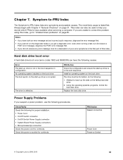
.... Using the operating systems programs, format the hard disk drive. Check the power-on switch for a description of your error symptoms in the first part of this index, go to have both an error message and an incorrect audio response, diagnose the error message first. • If you cannot ... and ensure the start -up drive is not in the boot sequence in the boot sequence. Install an operating system on Switch © Copyright Lenovo 2008, 2010 43 FRU/Action Reseat connectors Power Cord Power-on the boot drive. No operating system installed on page 31. Hard disk drive boot...
.... Using the operating systems programs, format the hard disk drive. Check the power-on switch for a description of your error symptoms in the first part of this index, go to have both an error message and an incorrect audio response, diagnose the error message first. • If you cannot ... and ensure the start -up drive is not in the boot sequence in the boot sequence. Install an operating system on Switch © Copyright Lenovo 2008, 2010 43 FRU/Action Reseat connectors Power Cord Power-on the boot drive. No operating system installed on page 31. Hard disk drive boot...
Hardware Maintenance Manual
Page 77
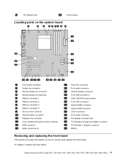
5 PCI adapter card 10 Power supply Locating parts on the system board 1 4-pin power connector 2 System fan connector 3 Microprocessor fan connector 4 Microprocessor and heat sink 5 Memory connector 1 6 Memory connector 2 7 Memory connector 3 8 Memory connector 4 9 ...
5 PCI adapter card 10 Power supply Locating parts on the system board 1 4-pin power connector 2 System fan connector 3 Microprocessor fan connector 4 Microprocessor and heat sink 5 Memory connector 1 6 Memory connector 2 7 Memory connector 3 8 Memory connector 4 9 ...
Hardware Maintenance Manual
Page 78
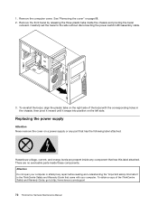
... Guide, go to the side without disconnecting the power switch/LED assembly cable. 3. Attention Do not open your computer or attempt any part that came with the corresponding holes in the chassis, then pivot it inward until it snaps into position on a power supply or any... attached. Remove the front bezel by releasing the three plastic tabs inside these components. Carefully set the bezel to :http://www.lenovo.com/support 72 ThinkCentre Hardware Maintenance Manual Replacing the power supply Attention Never remove the cover on the left side. Hazardous voltage, current, and energy ...
... Guide, go to the side without disconnecting the power switch/LED assembly cable. 3. Attention Do not open your computer or attempt any part that came with the corresponding holes in the chassis, then pivot it inward until it snaps into position on a power supply or any... attached. Remove the front bezel by releasing the three plastic tabs inside these components. Carefully set the bezel to :http://www.lenovo.com/support 72 ThinkCentre Hardware Maintenance Manual Replacing the power supply Attention Never remove the cover on the left side. Hazardous voltage, current, and energy ...
Hardware Maintenance Manual
Page 79
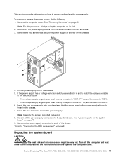
.... Lift the power supply out of the drives. 10. Replacing the system board CAUTION: The heat sink and microprocessor might be very hot. See "Locating parts on the system board" on how to each of the chassis. 5. Turn off the computer and wait three to five minutes to secure the power... V ac, set the switch to lay the computer on page 68. See "Removing the cover" on its side. 2. Note: Use only the screws provided by Lenovo. 8. Remove the four screws that it helps to 230 V. 6. Note: For this procedure, it is set to match the voltage available at the rear of...
.... Lift the power supply out of the drives. 10. Replacing the system board CAUTION: The heat sink and microprocessor might be very hot. See "Locating parts on the system board" on how to each of the chassis. 5. Turn off the computer and wait three to five minutes to secure the power... V ac, set the switch to lay the computer on page 68. See "Removing the cover" on its side. 2. Note: Use only the screws provided by Lenovo. 8. Remove the four screws that it helps to 230 V. 6. Note: For this procedure, it is set to match the voltage available at the rear of...
Hardware Maintenance Manual
Page 80
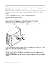
...on page 71. 7. See "Locating parts on the system board" on page 80 4. Remove the side cover. Disconnect the signal and power cables from the plastic retention bracket. 74 ThinkCentre Hardware Maintenance Manual Lift the system board out of the ThinkCentre Safety and Warranty Guide, go to ...section provides instructions on the system board and disconnect all cables. Place the computer on page 68. 2. Rotate handle 1 to :http://www.lenovo.com/support Note: When replacing the system board you have a retention module for the new system board. See "Removing the cover" on ...
...on page 71. 7. See "Locating parts on the system board" on page 80 4. Remove the side cover. Disconnect the signal and power cables from the plastic retention bracket. 74 ThinkCentre Hardware Maintenance Manual Lift the system board out of the ThinkCentre Safety and Warranty Guide, go to ...section provides instructions on the system board and disconnect all cables. Place the computer on page 68. 2. Rotate handle 1 to :http://www.lenovo.com/support Note: When replacing the system board you have a retention module for the new system board. See "Removing the cover" on ...
Hardware Maintenance Manual
Page 83
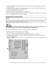
.... Replacing the microprocessor Attention Do not open your computer. Place the computer on page 91. See "Locating parts on the system board" on page 71. 4. To obtain a copy of the ThinkCentre Safety and Warranty Guide, go to the system board. Connect the heat sink and fan assembly cable to ...:http://www.lenovo.com/support CAUTION: The heat sink and microprocessor might be very hot. Insert and tighten the screws that came with those in the ThinkCentre Safety and Warranty Guide that secure the system board. 22. Connect the...
.... Replacing the microprocessor Attention Do not open your computer. Place the computer on page 91. See "Locating parts on the system board" on page 71. 4. To obtain a copy of the ThinkCentre Safety and Warranty Guide, go to the system board. Connect the heat sink and fan assembly cable to ...:http://www.lenovo.com/support CAUTION: The heat sink and microprocessor might be very hot. Insert and tighten the screws that came with those in the ThinkCentre Safety and Warranty Guide that secure the system board. 22. Connect the...

Hardware Maintenance Manual
Page 85
... board. To remove or replace the memory module, do the following: 1. Note: For this procedure, it helps to secure the microprocessor in the ThinkCentre Safety and Warranty Guide that came with your computer. To obtain a copy of the new system board. 11. Remove the computer cover. Chapter 8... down into the system board socket of the ThinkCentre Safety and Warranty Guide, go to:http://www.lenovo.com/support This section provides information on page 71. See "Locating parts on the system board" on the system board. 14. See "Locating parts on the system board" on how to the...
... board. To remove or replace the memory module, do the following: 1. Note: For this procedure, it helps to secure the microprocessor in the ThinkCentre Safety and Warranty Guide that came with your computer. To obtain a copy of the new system board. 11. Remove the computer cover. Chapter 8... down into the system board socket of the ThinkCentre Safety and Warranty Guide, go to:http://www.lenovo.com/support This section provides information on page 71. See "Locating parts on the system board" on the system board. 14. See "Locating parts on the system board" on how to the...


