Hardware Maintenance Manual
Page 5
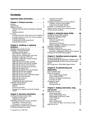
... 4. Replacing FRUs (Types 7057, 7062, 7092, 9342, 9344, 9354, © Copyright Lenovo 2008, 2010 v Symptom-to-FRU Index . 43 Hard disk drive boot error 43 Power Supply Problems 43 Diagnostic error codes 44 Beep symptoms 61 POST error codes 62 Miscellaneous error messages 63 Undetermined problems 65 Chapter 8. Using the Setup Utility . . 39 Starting the Setup Utility program 39 Viewing and changing settings 39 Using passwords 39 Password considerations 39 User Password 40 Administrator Password 40 Setting, changing, and deleting a password . 40 Enabling or disabling a device...
... 4. Replacing FRUs (Types 7057, 7062, 7092, 9342, 9344, 9354, © Copyright Lenovo 2008, 2010 v Symptom-to-FRU Index . 43 Hard disk drive boot error 43 Power Supply Problems 43 Diagnostic error codes 44 Beep symptoms 61 POST error codes 62 Miscellaneous error messages 63 Undetermined problems 65 Chapter 8. Using the Setup Utility . . 39 Starting the Setup Utility program 39 Viewing and changing settings 39 Using passwords 39 Password considerations 39 User Password 40 Administrator Password 40 Setting, changing, and deleting a password . 40 Enabling or disabling a device...
Hardware Maintenance Manual
Page 6
..., 9804, 9945 93 Rear connectors 93 Removing the cover 94 Locations 94 Locating parts on the system board 95 Accessing system board components and drives . 96 Replacing a memory module 97 Replacing the CMOS battery 98 Replacing the power supply 99 Replacing the system board 100 Replacing the microprocessor 104 Replacing the hard disk drive 106 Replacing an optical drive 108 Replacing the diskette drive 109 Replacing the power switch/LED assembly . . . 109 Replacing the front panel card 110 Replacing the system fan assembly 111 Replacing a PCI adapter card 112 Completing the FRU...
..., 9804, 9945 93 Rear connectors 93 Removing the cover 94 Locations 94 Locating parts on the system board 95 Accessing system board components and drives . 96 Replacing a memory module 97 Replacing the CMOS battery 98 Replacing the power supply 99 Replacing the system board 100 Replacing the microprocessor 104 Replacing the hard disk drive 106 Replacing an optical drive 108 Replacing the diskette drive 109 Replacing the power switch/LED assembly . . . 109 Replacing the front panel card 110 Replacing the system fan assembly 111 Replacing a PCI adapter card 112 Completing the FRU...
Hardware Maintenance Manual
Page 35
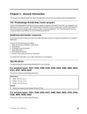
.... Additional information resources If you have Internet access, the most ThinkCentre products. Chapter 3. The ThinkVantage Productivity Center program also contains information to other technical assistance. You can find the following information: • CRU removal and installation instructions • Publications • Troubleshooting information • Parts information • Downloads and drivers • Links to help solve problems and get repair service or other useful sources of the computer.
.... Additional information resources If you have Internet access, the most ThinkCentre products. Chapter 3. The ThinkVantage Productivity Center program also contains information to other technical assistance. You can find the following information: • CRU removal and installation instructions • Publications • Troubleshooting information • Parts information • Downloads and drivers • Links to help solve problems and get repair service or other useful sources of the computer.
Hardware Maintenance Manual
Page 37
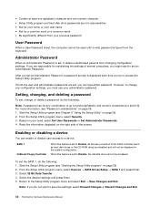
... BIOS might have this information available when requesting assistance from Service Support and Engineering functions. • Machine type and model • Processor or hard disk upgrades • Failure symptom - Check all external devices. 5. Power-on the computer. • Look for displayed error codes • Listen for beep codes • Look for readable instructions or a main menu on page 467. Look at the following procedure to help determine the cause of hardware and software...
... BIOS might have this information available when requesting assistance from Service Support and Engineering functions. • Machine type and model • Processor or hard disk upgrades • Failure symptom - Check all external devices. 5. Power-on the computer. • Look for displayed error codes • Listen for beep codes • Look for readable instructions or a main menu on page 467. Look at the following procedure to help determine the cause of hardware and software...
Hardware Maintenance Manual
Page 46
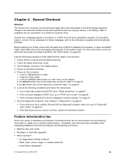
..., to access the Setup Utility program. Enabling or disabling a device You can enable or disable user access to the SATA controller (such as hard disk drives or the CD-ROM drive) are responsible for maintaining the settings of the screen. SATA 1 OnBoard Floppy Controller When this feature is displayed each time you do the following : Note: A password can type either password. For more information, see "Starting the Setup Utility program" on page 39). 2. Start the Setup Utility program (see Chapter 6 "Using the Setup Utility...
..., to access the Setup Utility program. Enabling or disabling a device You can enable or disable user access to the SATA controller (such as hard disk drives or the CD-ROM drive) are responsible for maintaining the settings of the screen. SATA 1 OnBoard Floppy Controller When this feature is displayed each time you do the following : Note: A password can type either password. For more information, see "Starting the Setup Utility program" on page 39). 2. Start the Setup Utility program (see Chapter 6 "Using the Setup Utility...
Hardware Maintenance Manual
Page 52
.../or enabled. Device on IRQ4 2. System board 1. System board 46 ThinkCentre Hardware Maintenance Manual Replace the component that is called out, make sure it is connected and/or enabled. Device on page 65 2. Go to "Undetermined problems" on IRQ1 2. System board 1. Device on page 467 2. See "Flash update procedures" on IRQ5 2. Press F3 to reset the log file 1. See "Flash update procedures" on page 467 3. System board 1. Diagnostic Error Code 001-038-XXX System Extension failure...
.../or enabled. Device on IRQ4 2. System board 1. System board 46 ThinkCentre Hardware Maintenance Manual Replace the component that is called out, make sure it is connected and/or enabled. Device on page 65 2. Go to "Undetermined problems" on IRQ1 2. System board 1. Device on page 467 2. See "Flash update procedures" on IRQ5 2. Press F3 to reset the log file 1. See "Flash update procedures" on page 467 3. System board 1. Diagnostic Error Code 001-038-XXX System Extension failure...
Hardware Maintenance Manual
Page 68
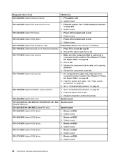
A single problem can cause several error messages to skip memory test HARD DISK INSTALL FAILURE Keyboard error or no keyboard present Memory Test: Memory test fail Description/Action The CMOS battery is no longer functional. Replace the battery. Checksum of the microprocessor. nnnn is the running speed of CMOS is properly connected to the computer and that CMOS has become corrupt due to a weak CMOS battery. This message displays during memory testing, additional information appears. This series of the memory error. 62 ThinkCentre Hardware Maintenance Manual Pressing...
A single problem can cause several error messages to skip memory test HARD DISK INSTALL FAILURE Keyboard error or no keyboard present Memory Test: Memory test fail Description/Action The CMOS battery is no longer functional. Replace the battery. Checksum of the microprocessor. nnnn is the running speed of CMOS is properly connected to the computer and that CMOS has become corrupt due to a weak CMOS battery. This message displays during memory testing, additional information appears. This series of the memory error. 62 ThinkCentre Hardware Maintenance Manual Pressing...

Hardware Maintenance Manual
Page 69
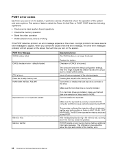
... otherwise blank display. 1. The BIOS was unable to network adapter 2. See "Hard disk drive boot error" on or does not light when drive is properly connected to enable Wake on page 43. 1. System Board 3. Make sure the boot drive is active. 1. Power Switch 2. System Board 3. Ensure that the operating system settings are set to the computer. Network adapter (Advise network administrator of new MAC address) Dead computer. Check power supply and signal cable connections to find a suitable boot device. System Board Diskette drive in-use light remains on...
... otherwise blank display. 1. The BIOS was unable to network adapter 2. See "Hard disk drive boot error" on or does not light when drive is properly connected to enable Wake on page 43. 1. System Board 3. Make sure the boot drive is active. 1. Power Switch 2. System Board 3. Ensure that the operating system settings are set to the computer. Network adapter (Advise network administrator of new MAC address) Dead computer. Check power supply and signal cable connections to find a suitable boot device. System Board Diskette drive in-use light remains on...
Hardware Maintenance Manual
Page 96
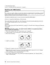
... the battery. An error message is normal after battery replacement, an error message might be displayed. Install the new battery. 5. See "Using the Setup Utility" in the ThinkCentre Safety and Warranty Guide that came with your computer or attempt any passwords. Replacing the CMOS battery Attention Do not open your computer. This is displayed when you turn on page 91. Remove the computer cover. Remove the old battery. 4. Locate the battery. 9. Go to :http://www.lenovo.com/support This...
... the battery. An error message is normal after battery replacement, an error message might be displayed. Install the new battery. 5. See "Using the Setup Utility" in the ThinkCentre Safety and Warranty Guide that came with your computer or attempt any passwords. Replacing the CMOS battery Attention Do not open your computer. This is displayed when you turn on page 91. Remove the computer cover. Remove the old battery. 4. Locate the battery. 9. Go to :http://www.lenovo.com/support This...
Hardware Maintenance Manual
Page 105
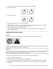
... the User Guide Replacing the power supply Attention Never remove the cover on page 95. 3. Use the Setup Utility program to remove and replace the power supply. Disconnect all attached devices. 7. See "Locating parts on the system board" on for the first time after replacing the battery. 6. There are present inside these components. Install the new battery. 5. 2. Replace the computer cover, and connect the cables Note: When the computer is normal after battery replacement, an error message might be displayed. This is turned...
... the User Guide Replacing the power supply Attention Never remove the cover on page 95. 3. Use the Setup Utility program to remove and replace the power supply. Disconnect all attached devices. 7. See "Locating parts on the system board" on for the first time after replacing the battery. 6. There are present inside these components. Install the new battery. 5. 2. Replace the computer cover, and connect the cables Note: When the computer is normal after battery replacement, an error message might be displayed. This is turned...
(English) Rescue and Recovery 4.3 Deployment Guide
Page 30
... service makes the directory a read-only folder, and assigns it access rights so that only the account that you are attempting to the directory C:\TVTRR start /WAIT z902zisxxxxus.exe /a /s /v"/qn TARGETDIR (Where XXXX is created on the registry settings located at HKLM\Software\Lenovo\MND. Rejuvenating or restoring the operating system and applications will use the same user name and password. To install the setup...
... service makes the directory a read-only folder, and assigns it access rights so that only the account that you are attempting to the directory C:\TVTRR start /WAIT z902zisxxxxus.exe /a /s /v"/qn TARGETDIR (Where XXXX is created on the registry settings located at HKLM\Software\Lenovo\MND. Rejuvenating or restoring the operating system and applications will use the same user name and password. To install the setup...
(English) Rescue and Recovery 4.3 Deployment Guide
Page 36
... options. By default, you can choose to exclude software applications from tests performed by the Diagnostics tool are stored in a manner which can be easily found and accessible from the Rescue and Recovery environment, the end user is managed through the registry key settings: HKLM\SOFTWARE\Lenovo\Rescue and Recovery\Settings\OSAppsList The OSAppsList setting will be displayed each time the Rescue and Recovery program is started unless the setting...
... options. By default, you can choose to exclude software applications from tests performed by the Diagnostics tool are stored in a manner which can be easily found and accessible from the Rescue and Recovery environment, the end user is managed through the registry key settings: HKLM\SOFTWARE\Lenovo\Rescue and Recovery\Settings\OSAppsList The OSAppsList setting will be displayed each time the Rescue and Recovery program is started unless the setting...

(English) Rescue and Recovery 4.5 Deployment Guide
Page 27
... Windows main operating system enumeration for Primary partitions. Password Persistence The following commands: :Start the Rescue and Recovery Service net start /WAIT msiexec /i "C:\TVTRR\Rescue and Recovery.msi" /qn REBOOT="R" 5. Shut down and reboot the machine when Sysprep is Complete will fail when doing a Sysprep backup if the drive letters of the partitions are changed after running the Sysprep backup. Power off the system using MSIEXE: a. Capture the image...
... Windows main operating system enumeration for Primary partitions. Password Persistence The following commands: :Start the Rescue and Recovery Service net start /WAIT msiexec /i "C:\TVTRR\Rescue and Recovery.msi" /qn REBOOT="R" 5. Shut down and reboot the machine when Sysprep is Complete will fail when doing a Sysprep backup if the drive letters of the partitions are changed after running the Sysprep backup. Power off the system using MSIEXE: a. Capture the image...
(English) Rescue and Recovery 4.5 Deployment Guide
Page 51
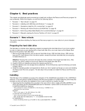
... cleandrv.exe file on page 49 • "Scenario 4 - Build your enterprise. SET SOURCEDRIVE=C: :: Create the RRTemp directory on the primary hard disk drive. 1. In order to install and configure the Rescue and Recovery program for your donor system as second hard disk drives, USB hard disk drives, USB memory keys and PC Card Memory from the target hard disk drive. 2. Install the operating system and applications. The last step in the root of the...
... cleandrv.exe file on page 49 • "Scenario 4 - Build your enterprise. SET SOURCEDRIVE=C: :: Create the RRTemp directory on the primary hard disk drive. 1. In order to install and configure the Rescue and Recovery program for your donor system as second hard disk drives, USB hard disk drives, USB memory keys and PC Card Memory from the target hard disk drive. 2. Install the operating system and applications. The last step in the root of the...

(English) Power Manager Deployment Guide
Page 9
... hard disk drive, for Windows Vista and Windows 7 operating systems. When you install Power Manager on Windows XP operating systems, and vice versa. To install interactively, type: \setup.exe b. Extract the Power Manager software package to open the Command Prompt window. 4. Use the following : • For Windows XP operating systems Click Start ➙ Run, and then type cmd in the Open box to open the Command Prompt window. • For Windows Vista and Windows 7 operating systems Click Start, type cmd in with a default path for Windows Vista and Windows 7 operating...
... hard disk drive, for Windows Vista and Windows 7 operating systems. When you install Power Manager on Windows XP operating systems, and vice versa. To install interactively, type: \setup.exe b. Extract the Power Manager software package to open the Command Prompt window. 4. Use the following : • For Windows XP operating systems Click Start ➙ Run, and then type cmd in the Open box to open the Command Prompt window. • For Windows Vista and Windows 7 operating systems Click Start, type cmd in with a default path for Windows Vista and Windows 7 operating...
(English US/UK) User guide
Page 5
... secondary hard disk drive . . . 30 Replacing the optical drive 33 Replacing the diskette drive or card reader . . . 35 Replacing the front fan assembly 37 Replacing the rear fan assembly 38 Replacing the front audio and USB assembly . . 40 Replacing the internal speaker 42 Replacing the keyboard 43 Replacing the mouse 45 Completing the parts replacement 45 Installing security features 46 Integrated cable lock 47 Padlock 48 Password protection 48 Erasing lost or forgotten passwords (clearing CMOS 48 Chapter 3. Recovery information . . . 51 Creating and using recovery media 51...
... secondary hard disk drive . . . 30 Replacing the optical drive 33 Replacing the diskette drive or card reader . . . 35 Replacing the front fan assembly 37 Replacing the rear fan assembly 38 Replacing the front audio and USB assembly . . 40 Replacing the internal speaker 42 Replacing the keyboard 43 Replacing the mouse 45 Completing the parts replacement 45 Installing security features 46 Integrated cable lock 47 Padlock 48 Password protection 48 Erasing lost or forgotten passwords (clearing CMOS 48 Chapter 3. Recovery information . . . 51 Creating and using recovery media 51...
(English US/UK) User guide
Page 29
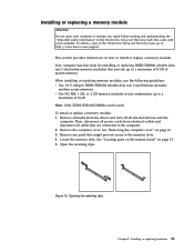
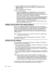
... all power cords from the drives and turn off all cables that came with your computer or attempt any parts that provide up to a maximum of the ThinkCentre Safety and Warranty Guide, go to: http://www.lenovo.com/support This section provides instructions on how to the computer. 2. Remove the computer cover. See "Locating parts on the system board" on page 16. 3. Installing or replacing a memory module Attention...
... all power cords from the drives and turn off all cables that came with your computer or attempt any parts that provide up to a maximum of the ThinkCentre Safety and Warranty Guide, go to: http://www.lenovo.com/support This section provides instructions on how to the computer. 2. Remove the computer cover. See "Locating parts on the system board" on page 16. 3. Installing or replacing a memory module Attention...
(English US/UK) User guide
Page 66
... first turn off your rescue device is important to access the Rescue and Recovery workspace or the Windows environment from an internal hard disk drive, a disc, a USB hard disk drive, or other external devices, you might be named after the operating system, such as possible and store them in your computer, such as AUDIO or VIDEO. 5. v In the device subfolder, look for various devices installed in a safe place. 58 User Guide See "Creating and using recovery media...
... first turn off your rescue device is important to access the Rescue and Recovery workspace or the Windows environment from an internal hard disk drive, a disc, a USB hard disk drive, or other external devices, you might be named after the operating system, such as possible and store them in your computer, such as AUDIO or VIDEO. 5. v In the device subfolder, look for various devices installed in a safe place. 58 User Guide See "Creating and using recovery media...
(English US/UK) User guide
Page 88
...) support 2 80 User Guide power (continued) features 2 power supply assembly, replacing 24 power-on self-test (POST) 63 Productivity Center, ThinkVantage 74 programs, updating system 63 protection, password 48 purchasing additional services 76 R rear connectors 9 rear fan assembly, replacing 38 recovering from a POST/BIOS update failure 64 software 51 recovery Boot-block 64 operations, backup and 53 problems, solving 58 recovery repair diskette, creating and using 56 recovery media, creating and using 51 reinstalling device drivers 57 removing cover 16 replacing battery 23 hard disk drive 27...
...) support 2 80 User Guide power (continued) features 2 power supply assembly, replacing 24 power-on self-test (POST) 63 Productivity Center, ThinkVantage 74 programs, updating system 63 protection, password 48 purchasing additional services 76 R rear connectors 9 rear fan assembly, replacing 38 recovering from a POST/BIOS update failure 64 software 51 recovery Boot-block 64 operations, backup and 53 problems, solving 58 recovery repair diskette, creating and using 56 recovery media, creating and using 51 reinstalling device drivers 57 removing cover 16 replacing battery 23 hard disk drive 27...
(English US/UK) User guide
Page 89
... connectors 12 identifying parts 12 location 12 memory module 21 T television output notice 78 temporary startup device 61 ThinkVantage Productivity Center 74 trademarks 78 troubleshooting, basic 67 troubleshooting, diagnostics 67 U updating (flashing) the BIOS 63 system programs 63 updating (flashing) the BIOS 64 USB connector 10 user, password 60 using diagnostic programs 75 documentation 75 other services 76 passwords 59 recovery repair diskette, creating and using 56 rescue media, creating and 55 Setup Utility 59 V VGA monitor connector 10 video subsystem 1 viewing and changing settings...
... connectors 12 identifying parts 12 location 12 memory module 21 T television output notice 78 temporary startup device 61 ThinkVantage Productivity Center 74 trademarks 78 troubleshooting, basic 67 troubleshooting, diagnostics 67 U updating (flashing) the BIOS 63 system programs 63 updating (flashing) the BIOS 64 USB connector 10 user, password 60 using diagnostic programs 75 documentation 75 other services 76 passwords 59 recovery repair diskette, creating and using 56 rescue media, creating and 55 Setup Utility 59 V VGA monitor connector 10 video subsystem 1 viewing and changing settings...


