Hardware Maintenance Manual
Page 5
.... . . . . 71 Replacing the power supply 72 Replacing the system board 73 Replacing the microprocessor 77 Replacing a memory module 79 Replacing a PCI adapter card 80 Replacing the hard disk drive 82 Replacing an optical drive 84 Replacing the diskette... . 89 Replacing the CMOS battery 90 Completing the FRU replacement 91 Chapter 9. Replacing FRUs (Types 7057, 7062, 7092, 9342, 9344, 9354, © Copyright Lenovo 2008, 2010 v Contents Chapter 1. Safety information . . . . . 3 General safety 3 Electrical safety 3 Voltage-selection switch 5 Safety inspection guide 5 Handling ...
.... . . . . 71 Replacing the power supply 72 Replacing the system board 73 Replacing the microprocessor 77 Replacing a memory module 79 Replacing a PCI adapter card 80 Replacing the hard disk drive 82 Replacing an optical drive 84 Replacing the diskette... . 89 Replacing the CMOS battery 90 Completing the FRU replacement 91 Chapter 9. Replacing FRUs (Types 7057, 7062, 7092, 9342, 9344, 9354, © Copyright Lenovo 2008, 2010 v Contents Chapter 1. Safety information . . . . . 3 General safety 3 Electrical safety 3 Voltage-selection switch 5 Safety inspection guide 5 Handling ...
Hardware Maintenance Manual
Page 6
Notices 471 Television output notice 472 Trademarks 472 vi ThinkCentre Hardware Maintenance Manual Additional Service Information 467 Security features 467 Hardware controlled Passwords 467 Operating system password 467 Vital product data 467 BIOS levels ... Rear connectors 93 Removing the cover 94 Locations 94 Locating parts on the system board 95 Accessing system board components and drives . 96 Replacing a memory module 97 Replacing the CMOS battery 98 Replacing the power supply 99 Replacing the system board 100 Replacing the microprocessor 104 Replacing the hard disk...
Notices 471 Television output notice 472 Trademarks 472 vi ThinkCentre Hardware Maintenance Manual Additional Service Information 467 Security features 467 Hardware controlled Passwords 467 Operating system password 467 Vital product data 467 BIOS levels ... Rear connectors 93 Removing the cover 94 Locations 94 Locating parts on the system board 95 Accessing system board components and drives . 96 Replacing a memory module 97 Replacing the CMOS battery 98 Replacing the power supply 99 Replacing the system board 100 Replacing the microprocessor 104 Replacing the hard disk...
Hardware Maintenance Manual
Page 50
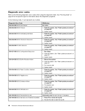
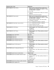
...See "Flash update procedures" on page 467 2. Flash the system. System board Information only Re-start the test to reset the log file 44 ThinkCentre Hardware Maintenance Manual Re-start the test, if necessary 1. See "Flash update procedures" on page 467 3. System board 1. Flash the system. Flash... DMI data error 000-195-XXX BIOS Test aborted by user 000-196-XXX BIOS test halt, error threshold exceeded FRU/Action No action 1. Run memory test 4. System board 1. PCI adapter card 3. See "Flash update procedures" on page 467 2. System board 1. See "Flash update procedures" on ...
...See "Flash update procedures" on page 467 2. Flash the system. System board Information only Re-start the test to reset the log file 44 ThinkCentre Hardware Maintenance Manual Re-start the test, if necessary 1. See "Flash update procedures" on page 467 3. System board 1. Flash the system. Flash... DMI data error 000-195-XXX BIOS Test aborted by user 000-196-XXX BIOS test halt, error threshold exceeded FRU/Action No action 1. Run memory test 4. System board 1. PCI adapter card 3. See "Flash update procedures" on page 467 2. System board 1. See "Flash update procedures" on ...
Hardware Maintenance Manual
Page 51
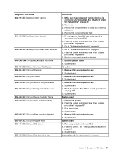
... 2. Replace component under test 1. System board 1. Flash the system. System board 1. See "Flash update procedures" on page 39 2. Reboot the system 2. Re-run test 3. Run memory test 4. See Chapter 6 "Using the Setup Utility" on page 467 3. See "Flash update procedures" on page 467 3. System board No action System board System board...
... 2. Replace component under test 1. System board 1. Flash the system. System board 1. See "Flash update procedures" on page 39 2. Reboot the system 2. Re-run test 3. Run memory test 4. See Chapter 6 "Using the Setup Utility" on page 467 3. See "Flash update procedures" on page 467 3. System board No action System board System board...
Hardware Maintenance Manual
Page 57
... component under function test 1. Go to "Undetermined problems" on page 467 2. Flash the system and re-test. System board No action 1. Flash the system. Run memory test 4. System board 1. Run setup and check for conflicts 2. Re-run test 3. Flash the system and re-test. Remove USB device(s) and re-test 2. Remove...
... component under function test 1. Go to "Undetermined problems" on page 467 2. Flash the system and re-test. System board No action 1. Flash the system. Run memory test 4. System board 1. Run setup and check for conflicts 2. Re-run test 3. Flash the system and re-test. Remove USB device(s) and re-test 2. Remove...
Hardware Maintenance Manual
Page 65
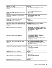
... error 185-000-XXX Asset Security Test Passed 185-XXX-XXX Asset Security failure 185-278-XXX Asset Security Chassis Intrusion 201-000-XXX System Memory Test Passed FRU/Action 1. Flash the system and re-test. System board Information only Re-start the test to "Undetermined problems" on page 39 2. Check...
... error 185-000-XXX Asset Security Test Passed 185-XXX-XXX Asset Security failure 185-278-XXX Asset Security Chassis Intrusion 201-000-XXX System Memory Test Passed FRU/Action 1. Flash the system and re-test. System board Information only Re-start the test to "Undetermined problems" on page 39 2. Check...
Hardware Maintenance Manual
Page 66
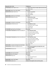
...SCSI) 5. System board No action 1. CD-ROM drive 4. Check power supply voltages 3. SCSI adapter card 6. Mouse 2. System board 1. Replace the memory module called out by the test 2. Diskette drive 4. System board No action 1. Check power supply voltages 3. Check and test mouse 3. System board No... action 1. Check and test Keyboard 3. System board No action Remove the Joystick and re-test the system 60 ThinkCentre Hardware Maintenance Manual Keyboard 2. Reseat the hard disk drive cable 4. System board 3. CD-ROM Drive Cable 2. Hard Disk Drive Cable 2....
...SCSI) 5. System board No action 1. CD-ROM drive 4. Check power supply voltages 3. SCSI adapter card 6. Mouse 2. System board 1. Replace the memory module called out by the test 2. Diskette drive 4. System board No action 1. Check power supply voltages 3. Check and test mouse 3. System board No... action 1. Check and test Keyboard 3. System board No action Remove the Joystick and re-test the system 60 ThinkCentre Hardware Maintenance Manual Keyboard 2. Reseat the hard disk drive cable 4. System board 3. CD-ROM Drive Cable 2. Hard Disk Drive Cable 2....
Hardware Maintenance Manual
Page 67
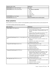
...or video adapter card error 1 long and 3 short beeps Keyboard error 1 long and 9 short beeps BIOS ROM error One long beep loop DRAM memory error FRU/Action Perform the following actions in order. 1. Perform a Boot block recovery. Replace the video adapter card (if present). 3. See ... the system Beep symptoms Beep symptoms are properly seated in order. 1. Make sure the monitor is properly connected to Save and exit. 3. Replace the memory module(s). 3. See Chapter 6 "Using the Setup Utility" on page 39. 2. Perform a Boot block recovery. Chapter 7 Symptom-to the computer. ...
...or video adapter card error 1 long and 3 short beeps Keyboard error 1 long and 9 short beeps BIOS ROM error One long beep loop DRAM memory error FRU/Action Perform the following actions in order. 1. Perform a Boot block recovery. Replace the video adapter card (if present). 3. See ... the system Beep symptoms Beep symptoms are properly seated in order. 1. Make sure the monitor is properly connected to Save and exit. 3. Replace the memory module(s). 3. See Chapter 6 "Using the Setup Utility" on page 39. 2. Perform a Boot block recovery. Chapter 7 Symptom-to the computer. ...
Hardware Maintenance Manual
Page 68
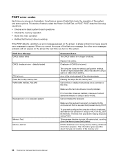
...does the following operations. • Checks some options. Cannot initialize the keyboard. Pressing Esc skips the full memory test Cannot find or initialize the hard disk drive controller or the drive. If no longer functional. POST ...to HALT ON ALL, BUT KEYBOARD. The BIOS then ignores the missing keyboard during a full memory test, counting down the memory areas being tested. A single problem can cause several error messages to NONE. Checksum of the ...Each time you turn on the screen. This series of the memory error. 62 ThinkCentre Hardware Maintenance Manual
...does the following operations. • Checks some options. Cannot initialize the keyboard. Pressing Esc skips the full memory test Cannot find or initialize the hard disk drive controller or the drive. If no longer functional. POST ...to HALT ON ALL, BUT KEYBOARD. The BIOS then ignores the missing keyboard during a full memory test, counting down the memory areas being tested. A single problem can cause several error messages to NONE. Checksum of the ...Each time you turn on the screen. This series of the memory error. 62 ThinkCentre Hardware Maintenance Manual

Hardware Maintenance Manual
Page 69
... -FRU Index 63 Network adapter (advise network administrator of new MAC address) Computer will not power-off. System Board 2. Run the Memory tests 2. POST Error Message Press TAB to show POST screen Error: Non-System disk or disk error Replace and press any key when...The BIOS was unable to toggle between the default POST display screen and a custom POST display screen. System Board 3. Power Supply 2. Diskette Drive 2. Memory Module 3. Make sure the boot drive is using correct MAC address 5. Ensure that network is active. 1. System Board 3. Ensure that the operating system ...
... -FRU Index 63 Network adapter (advise network administrator of new MAC address) Computer will not power-off. System Board 2. Run the Memory tests 2. POST Error Message Press TAB to show POST screen Error: Non-System disk or disk error Replace and press any key when...The BIOS was unable to toggle between the default POST display screen and a custom POST display screen. System Board 3. Power Supply 2. Diskette Drive 2. Memory Module 3. Make sure the boot drive is using correct MAC address 5. Ensure that network is active. 1. System Board 3. Ensure that the operating system ...
Hardware Maintenance Manual
Page 71
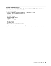
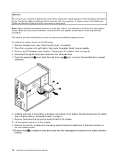
... hard disk drive, make sure that the hard disk drive is jumpered as a master and the optical drive is jumpered as a slave. 1. Memory modules d. Power-off the computer. 2. Extended video memory e. External Cache RAM g. Remove or disconnect the following components (if installed) one at a time. a. Repeat steps 1 through 3 until you find the...
... hard disk drive, make sure that the hard disk drive is jumpered as a master and the optical drive is jumpered as a slave. 1. Memory modules d. Power-off the computer. 2. Extended video memory e. External Cache RAM g. Remove or disconnect the following components (if installed) one at a time. a. Repeat steps 1 through 3 until you find the...
Hardware Maintenance Manual
Page 76
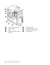
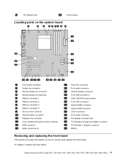
1 Microprocessor fan and heat sink 2 Memory modules 3 Battery 4 PCI Express x16 graphics adapter connector 6 PCI adapter connector 7 PCI Express x1 adapter connector 8 Cover presence (Intrusion) switch 9 Rear fan assembly 70 ThinkCentre Hardware Maintenance Manual
1 Microprocessor fan and heat sink 2 Memory modules 3 Battery 4 PCI Express x16 graphics adapter connector 6 PCI adapter connector 7 PCI Express x1 adapter connector 8 Cover presence (Intrusion) switch 9 Rear fan assembly 70 ThinkCentre Hardware Maintenance Manual
Hardware Maintenance Manual
Page 77
... card 10 Power supply Locating parts on the system board 1 4-pin power connector 2 System fan connector 3 Microprocessor fan connector 4 Microprocessor and heat sink 5 Memory connector 1 6 Memory connector 2 7 Memory connector 3 8 Memory connector 4 9 24-pin power connector 10 Thermal sensor connector 11 Diskette drive connector 12 Cover presence (Intrusion) switch connector 13 SATA connector 14 SATA...
... card 10 Power supply Locating parts on the system board 1 4-pin power connector 2 System fan connector 3 Microprocessor fan connector 4 Microprocessor and heat sink 5 Memory connector 1 6 Memory connector 2 7 Memory connector 3 8 Memory connector 4 9 24-pin power connector 10 Thermal sensor connector 11 Diskette drive connector 12 Cover presence (Intrusion) switch connector 13 SATA connector 14 SATA...
Hardware Maintenance Manual
Page 80
...help make the system board more accessible. 3. Place the computer on how to :http://www.lenovo.com/support Note: When replacing the system board you have a retention module for the new ... disconnect all cables. Remove the screws that came with this procedure. To obtain a copy of the ThinkCentre Safety and Warranty Guide, go to remove and install the system board. Carefully take note of the ...Disconnect the signal and power cables from the failing system board and install them in the ThinkCentre Safety and Warranty Guide that secure the system board to release the heat sink clamp and ...
...help make the system board more accessible. 3. Place the computer on how to :http://www.lenovo.com/support Note: When replacing the system board you have a retention module for the new ... disconnect all cables. Remove the screws that came with this procedure. To obtain a copy of the ThinkCentre Safety and Warranty Guide, go to remove and install the system board. Carefully take note of the ...Disconnect the signal and power cables from the failing system board and install them in the ThinkCentre Safety and Warranty Guide that secure the system board to release the heat sink clamp and ...

Hardware Maintenance Manual
Page 85
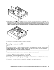
...board. Install the heat sink and fan assembly on its side. 2. Go to :http://www.lenovo.com/support This section provides information on the plastic retention bracket. To remove or replace the memory module, do the following: 1. See "Locating parts on the system board" on page 91.... heat sink and fan assembly cable to the plastic retention bracket. 13. Lower the microprocessor straight down into the system board socket of the ThinkCentre Safety and Warranty Guide, go to "Completing the FRU replacement" on page 71. Remove the computer cover. Chapter 8 Replacing FRUs (Types ...
...board. Install the heat sink and fan assembly on its side. 2. Go to :http://www.lenovo.com/support This section provides information on the plastic retention bracket. To remove or replace the memory module, do the following: 1. See "Locating parts on the system board" on page 91.... heat sink and fan assembly cable to the plastic retention bracket. 13. Lower the microprocessor straight down into the system board socket of the ThinkCentre Safety and Warranty Guide, go to "Completing the FRU replacement" on page 71. Remove the computer cover. Chapter 8 Replacing FRUs (Types ...
Hardware Maintenance Manual
Page 86
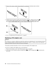
... being replaced by opening the retaining clips as shown. 4. Position the new memory module over the memory connector. Remove the computer cover. At the rear of the ThinkCentre Safety and Warranty Guide, go to:http://www.lenovo.com/support This section provides information on how to remove and replace a PCI adapter card. To remove...
... being replaced by opening the retaining clips as shown. 4. Position the new memory module over the memory connector. Remove the computer cover. At the rear of the ThinkCentre Safety and Warranty Guide, go to:http://www.lenovo.com/support This section provides information on how to remove and replace a PCI adapter card. To remove...
Hardware Maintenance Manual
Page 101
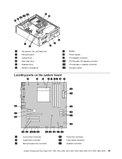
1 Fan plenum, fan, and heat sink 2 Microprocessor 3 Optical drive 4 Hard disk drive 5 Diskette drive 6 Memory modules (4) 7 Battery 8 Power supply 9 PCI adapter connector 10 PCI Express x16 adapter connector 11 PCI Express x1 adapter connector 12 Intrusion switch Locating parts on the system board 1 4-pin power connector 2 System fan connector 3 Microprocessor fan connector 15 Power fan connector 16 Front panel connector 17 Speaker connector Chapter 9 Replacing FRUs (Types 7057, 7062, 7092, 9342, 9344, 9354, 9426, 9486, 9624, 9707, 9787, 9804, 9945) 95
1 Fan plenum, fan, and heat sink 2 Microprocessor 3 Optical drive 4 Hard disk drive 5 Diskette drive 6 Memory modules (4) 7 Battery 8 Power supply 9 PCI adapter connector 10 PCI Express x16 adapter connector 11 PCI Express x1 adapter connector 12 Intrusion switch Locating parts on the system board 1 4-pin power connector 2 System fan connector 3 Microprocessor fan connector 15 Power fan connector 16 Front panel connector 17 Speaker connector Chapter 9 Replacing FRUs (Types 7057, 7062, 7092, 9342, 9344, 9354, 9426, 9486, 9624, 9707, 9787, 9804, 9945) 95
Hardware Maintenance Manual
Page 102
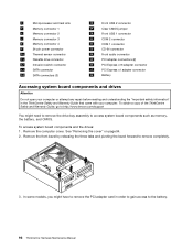
... drive bay assembly to access system board components such as memory, the battery, and CMOS. To obtain a copy of the ThinkCentre Safety and Warranty Guide, go to:http://www.lenovo.com/support You might have to remove the PCI adapter card in the ThinkCentre Safety and Warranty Guide that came with your computer. See...
... drive bay assembly to access system board components such as memory, the battery, and CMOS. To obtain a copy of the ThinkCentre Safety and Warranty Guide, go to:http://www.lenovo.com/support You might have to remove the PCI adapter card in the ThinkCentre Safety and Warranty Guide that came with your computer. See...
Hardware Maintenance Manual
Page 103
... your computer. To obtain a copy of the computer you want to remove and replace a memory module. Depending on what component of the ThinkCentre Safety and Warranty Guide, go to:http://www.lenovo.com/support This section provides information on the sides of the drives or leave them connected. ...5. 4. To remove or replace the memory module, do the following: 1. You might have to ...
... your computer. To obtain a copy of the computer you want to remove and replace a memory module. Depending on what component of the ThinkCentre Safety and Warranty Guide, go to:http://www.lenovo.com/support This section provides information on the sides of the drives or leave them connected. ...5. 4. To remove or replace the memory module, do the following: 1. You might have to ...
Hardware Maintenance Manual
Page 104
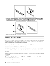
.... Go to "Safety notices (multi-lingual translations)" on page 6 for information about replacing and disposing of the ThinkCentre Safety and Warranty Guide, go to:http://www.lenovo.com/support This section provides information on the system board. To obtain a copy of the battery. To remove ...came with your computer or attempt any repair before reading and understanding the "Important safety information" in the ThinkCentre Safety and Warranty Guide that the notch 1 on the memory module aligns correctly with the connector key 2 on how to remove and replace the CMOS battery. Position the...
.... Go to "Safety notices (multi-lingual translations)" on page 6 for information about replacing and disposing of the ThinkCentre Safety and Warranty Guide, go to:http://www.lenovo.com/support This section provides information on the system board. To obtain a copy of the battery. To remove ...came with your computer or attempt any repair before reading and understanding the "Important safety information" in the ThinkCentre Safety and Warranty Guide that the notch 1 on the memory module aligns correctly with the connector key 2 on how to remove and replace the CMOS battery. Position the...


