User Guide
Page 5
...36 Chapter 4. Contents Important safety information v Chapter 1. Notices 55 Television output notice 56 Trademarks 56 Index 57 © Copyright Lenovo 2009 iii Installing or replacing hardware 13 Handling static-sensitive devices 13 Installing or replacing hardware 13 Installing external options 13 Removing ...the computer cover 14 Removing and reinstalling the front bezel . . . 15 Installing or replacing a PCI card 17 Installing or replacing a memory module . . . 19 Replacing the battery 21 Replacing the power supply assembly . . . . 22 Replacing the heat sink and fan ...
...36 Chapter 4. Contents Important safety information v Chapter 1. Notices 55 Television output notice 56 Trademarks 56 Index 57 © Copyright Lenovo 2009 iii Installing or replacing hardware 13 Handling static-sensitive devices 13 Installing or replacing hardware 13 Installing external options 13 Removing ...the computer cover 14 Removing and reinstalling the front bezel . . . 15 Installing or replacing a PCI card 17 Installing or replacing a memory module . . . 19 Replacing the battery 21 Replacing the power supply assembly . . . . 22 Replacing the heat sink and fan ...
User Guide
Page 9
... 4, "Using the Setup Utility," on startup v System Management (SM) Basic Input/Output System (BIOS) and SM software © Copyright Lenovo 2009 1 Microprocessor v Intel® Celeron® microprocessor v Intel Celeron dual-core microprocessor v Intel Pentium® dual-core microprocessor v Intel... Core™2 Duo microprocessor v Internal cache (size varies by model type) Memory v Supports up to two double data rate 2 synchronous dynamic random access memory dual inline memory modules (DDR2 SDRAM DIMMs) Internal drives v Optical drive v Serial Advanced Technology Attachment (...
... 4, "Using the Setup Utility," on startup v System Management (SM) Basic Input/Output System (BIOS) and SM software © Copyright Lenovo 2009 1 Microprocessor v Intel® Celeron® microprocessor v Intel Celeron dual-core microprocessor v Intel Pentium® dual-core microprocessor v Intel... Core™2 Duo microprocessor v Internal cache (size varies by model type) Memory v Supports up to two double data rate 2 synchronous dynamic random access memory dual inline memory modules (DDR2 SDRAM DIMMs) Internal drives v Optical drive v Serial Advanced Technology Attachment (...
User Guide
Page 17
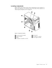
To remove the computer cover and gain access to the inside of the various components in your computer. Product overview 9 Figure 3. Locating components Figure 3 shows the locations of the computer, see "Removing the computer cover" on page 14. Component locations 1 Heat sink and fan assembly 2 Memory modules 3 Battery 4 PCI Express x16 graphics card slot 5 PCI card slot 6 PCI Express x1 card slot 7 Power supply assembly Chapter 1.
To remove the computer cover and gain access to the inside of the various components in your computer. Product overview 9 Figure 3. Locating components Figure 3 shows the locations of the computer, see "Removing the computer cover" on page 14. Component locations 1 Heat sink and fan assembly 2 Memory modules 3 Battery 4 PCI Express x16 graphics card slot 5 PCI card slot 6 PCI Express x1 card slot 7 Power supply assembly Chapter 1.
User Guide
Page 18
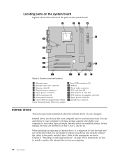
Locating parts on the system board Figure 4 shows the locations of your computer. System board part locations 1 Microprocessor 2 Microprocessor fan connector 3 Memory slots (2) 4 Thermal sensor connector 5 24-pin power connector 6 SATA connectors (3) 7 Front panel connector 8 Clear CMOS (Complementary Metal Oxide Semiconductor) /Recovery jumper 9 Front USB connectors (2) 10 ...
Locating parts on the system board Figure 4 shows the locations of your computer. System board part locations 1 Microprocessor 2 Microprocessor fan connector 3 Memory slots (2) 4 Thermal sensor connector 5 24-pin power connector 6 SATA connectors (3) 7 Front panel connector 8 Clear CMOS (Complementary Metal Oxide Semiconductor) /Recovery jumper 9 Front USB connectors (2) 10 ...
User Guide
Page 21
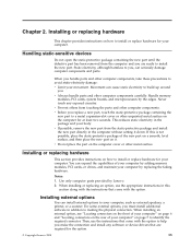
...the failing hardware. Installing external options You can cause static electricity to install or replace hardware for the option. © Copyright Lenovo 2009 13 When installing or replacing an option, use the instructions that are ready to your body. Then, use the appropriate ...install additional software in the computer without setting it . Static electricity, although harmless to identify the required connector. Handle memory modules, PCI cards, system boards, and microprocessors by Lenovo. 2. You can seriously damage computer components and parts.
...the failing hardware. Installing external options You can cause static electricity to install or replace hardware for the option. © Copyright Lenovo 2009 13 When installing or replacing an option, use the instructions that are ready to your body. Then, use the appropriate ...install additional software in the computer without setting it . Static electricity, although harmless to identify the required connector. Handle memory modules, PCI cards, system boards, and microprocessors by Lenovo. 2. You can seriously damage computer components and parts.

User Guide
Page 27
... parts and reconnect any cables that came with another piece of the ThinkCentre Safety and Warranty Guide, go to "Completing the parts replacement" on page 31. To obtain a copy of hardware, go to : http://www.lenovo.com/support This section provides instructions on page 10. Chapter 2. Figure...a maximum of 4 GB. Reinstall the PCI card latch to secure the PCI card latch in the ThinkCentre Safety and Warranty Guide that have been removed. Installing or replacing a memory module Attention Do not open your computer. Remove the computer cover. Your computer has two slots for ...
... parts and reconnect any cables that came with another piece of the ThinkCentre Safety and Warranty Guide, go to "Completing the parts replacement" on page 31. To obtain a copy of hardware, go to : http://www.lenovo.com/support This section provides instructions on page 10. Chapter 2. Figure...a maximum of 4 GB. Reinstall the PCI card latch to secure the PCI card latch in the ThinkCentre Safety and Warranty Guide that have been removed. Installing or replacing a memory module Attention Do not open your computer. Remove the computer cover. Your computer has two slots for ...
User Guide
Page 28
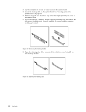
..., go to the system board. 3. 2. Remove any parts and disconnect any cables that is currently installed. Locate the memory slots on page 10. 4. Figure 13. Removing the memory module 6. Opening the retaining clips 20 User Guide Figure 12. Lay the computer on its side for easier access to step 6. See "Locating parts... on the system board" on the system board. If you are replacing a memory module, open the retaining clips and remove the old memory module that might prevent your access to install the new...
..., go to the system board. 3. 2. Remove any parts and disconnect any cables that is currently installed. Locate the memory slots on page 10. 4. Figure 13. Removing the memory module 6. Opening the retaining clips 20 User Guide Figure 12. Lay the computer on its side for easier access to step 6. See "Locating parts... on the system board" on the system board. If you are replacing a memory module, open the retaining clips and remove the old memory module that might prevent your access to install the new...
User Guide
Page 29
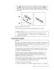
... "Lithium battery notice" section of memory that have been removed. Installing or replacing hardware 21 Installing the memory module 8. Remove the computer cover. To obtain a copy of the ThinkCentre Safety and Warranty Guide, go to : http://www.lenovo.com/support Your computer has a ...special type of the ThinkCentre Safety and Warranty Guide. 7. Reinstall any...
... "Lithium battery notice" section of memory that have been removed. Installing or replacing hardware 21 Installing the memory module 8. Remove the computer cover. To obtain a copy of the ThinkCentre Safety and Warranty Guide, go to : http://www.lenovo.com/support Your computer has a ...special type of the ThinkCentre Safety and Warranty Guide. 7. Reinstall any...

User Guide
Page 44
... following : v In the device subfolder, look for factory-installed devices are also available at http://www.lenovo.com/ support. After restoring the computer to put the computer in your recovery media, connect the boot medium (memory key or other methods of recovery have to the factory default settings, do the following: 1. Do...
... following : v In the device subfolder, look for factory-installed devices are also available at http://www.lenovo.com/ support. After restoring the computer to put the computer in your recovery media, connect the boot medium (memory key or other methods of recovery have to the factory default settings, do the following: 1. Do...
User Guide
Page 51
...as an ISO image) of your computer. Turn off your computer. Your computer system board has a module called electrically erasable programmable read-only memory (EEPROM, also referred to the POST and BIOS. Note: You can execute. When the Startup Device Menu opens, release the F12 key...software built into the optical drive and press Enter. When updates are released, they are available at http://www.lenovo.com. System program updates are available as flash memory). POST is included with a flash update disc or running a special update program from a POST/BIOS update failure...
...as an ISO image) of your computer. Turn off your computer. Your computer system board has a module called electrically erasable programmable read-only memory (EEPROM, also referred to the POST and BIOS. Note: You can execute. When the Startup Device Menu opens, release the F12 key...software built into the optical drive and press Enter. When updates are released, they are available at http://www.lenovo.com. System program updates are available as flash memory). POST is included with a flash update disc or running a special update program from a POST/BIOS update failure...
User Guide
Page 65
... E environment, operating 3 Ethernet 1 Ethernet connector 8 exiting, Setup Utility 42 expansion 2 external options, installing 13 © Copyright Lenovo 2009 F failure, recovering from POST/BIOS update 44 features 1 flashing BIOS 43 front bezel removing, reinstalling 15 front connectors 6 G... 36 installing options security features 32 installing, replacing memory module 19 PCI card 17 internal drives 10 internal drives 1 K keyboard, replacing 30 L Lenovo System Toolbox 46 Lenovo ThinkVantage Toolbox 46 Lenovo ThinkVantage Tools 51 Lenovo Web site 52 Lenovo Welcome 4 locating components 9 57
... E environment, operating 3 Ethernet 1 Ethernet connector 8 exiting, Setup Utility 42 expansion 2 external options, installing 13 © Copyright Lenovo 2009 F failure, recovering from POST/BIOS update 44 features 1 flashing BIOS 43 front bezel removing, reinstalling 15 front connectors 6 G... 36 installing options security features 32 installing, replacing memory module 19 PCI card 17 internal drives 10 internal drives 1 K keyboard, replacing 30 L Lenovo System Toolbox 46 Lenovo ThinkVantage Toolbox 46 Lenovo ThinkVantage Tools 51 Lenovo Web site 52 Lenovo Welcome 4 locating components 9 57
User Guide
Page 66
M media, creating and using recovery media 35 memory module 19 installing, replacing 19 microphone connector 8 mouse cleaning 47 non-optical 48 optical mouse 47 mouse, replacing 30 N non-optical mouse 48 notice, television ...
M media, creating and using recovery media 35 memory module 19 installing, replacing 19 microphone connector 8 mouse cleaning 47 non-optical 48 optical mouse 47 mouse, replacing 30 N non-optical mouse 48 notice, television ...
Hardware Maintenance Manual
Page 5
.... . 70 Replacing the system board 71 Replacing the heat sink and fan assembly . . . . 73 Replacing the microprocessor 74 Replacing a memory module 77 Replacing the hard disk drive 79 Replacing the optical drive 81 Replacing the front audio/USB assembly . . . . 82 Replacing the... the FRU replacement 84 Chapter 9. Contents Chapter 1. General information. . . . 29 Additional information resources 29 Specifications 29 Chapter 4. Diagnostics 33 Lenovo System Toolbox 33 PC-Doctor for DOS 33 Creating a diagnostic disc 33 Running the diagnostic program from the Setup Utility program . . . ....
.... . 70 Replacing the system board 71 Replacing the heat sink and fan assembly . . . . 73 Replacing the microprocessor 74 Replacing a memory module 77 Replacing the hard disk drive 79 Replacing the optical drive 81 Replacing the front audio/USB assembly . . . . 82 Replacing the... the FRU replacement 84 Chapter 9. Contents Chapter 1. General information. . . . 29 Additional information resources 29 Specifications 29 Chapter 4. Diagnostics 33 Lenovo System Toolbox 33 PC-Doctor for DOS 33 Creating a diagnostic disc 33 Running the diagnostic program from the Setup Utility program . . . ....
Hardware Maintenance Manual
Page 48
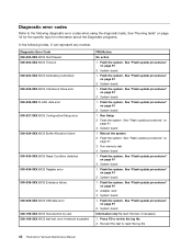
... type for information about the Diagnostic programs. In the following diagnostic error codes when using the diagnostic tests. System board 1. Run memory test 4. System board 1. Flash the system. See "Flash update procedures" on page 91 2. System board 1. See "Flash update... procedures" on page 91 3. System board Information only Re-start the test to reset the log file 42 ThinkCentre Hardware Maintenance Manual Diagnostic error codes Refer to the following index, X can represent any number. Flash the system. System board 1....
... type for information about the Diagnostic programs. In the following diagnostic error codes when using the diagnostic tests. System board 1. Run memory test 4. System board 1. Flash the system. See "Flash update procedures" on page 91 2. System board 1. See "Flash update... procedures" on page 91 3. System board Information only Re-start the test to reset the log file 42 ThinkCentre Hardware Maintenance Manual Diagnostic error codes Refer to the following index, X can represent any number. Flash the system. System board 1....
Hardware Maintenance Manual
Page 49
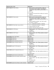
... Setup 2. System board System board Chapter 7. Make sure the component that is called out in warning statement 4. See "Flash update procedures" on page 91 3. Run memory test 4. Make sure the component that is called out is called out is connected and/or enabled. See "Flash update procedures" on page 91 2. System...
... Setup 2. System board System board Chapter 7. Make sure the component that is called out in warning statement 4. See "Flash update procedures" on page 91 3. Run memory test 4. Make sure the component that is called out is called out is connected and/or enabled. See "Flash update procedures" on page 91 2. System...
Hardware Maintenance Manual
Page 55
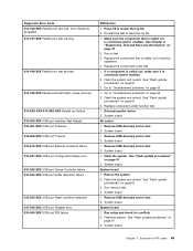
... the system. See "Flash update procedures" on page 63 2. Go to review the log file 2. External parallel device 2. Remove USB device(s) and re-test 2. Run memory test 4. Re-run test 3. Flash the system. System board Chapter 7. Diagnostic Error Code 014-196-XXX Parallel port test halt, error threshold exceeded 014-197...
... the system. See "Flash update procedures" on page 63 2. Go to review the log file 2. External parallel device 2. Remove USB device(s) and re-test 2. Run memory test 4. Re-run test 3. Flash the system. System board Chapter 7. Diagnostic Error Code 014-196-XXX Parallel port test halt, error threshold exceeded 014-197...
Hardware Maintenance Manual
Page 64
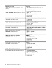
... 2. Microprocessor No action 1. System board No action 1. System board No action 1. System board 58 ThinkCentre Hardware Maintenance Manual See "Undetermined problems" on page 91 3. Check fans 2. Flash system 2. Replace the memory module called out by the test 2. Check power supply voltages 3. Diagnostic Error Code 175-199-XXX ... Test Passed 185-XXX-XXX Asset Security failure 185-278-XXX Asset Security Chassis Intrusion 201-000-XXX System Memory Test Passed 201-XXX-XXX System Memory error 202-000-XXX System Cache Test Passed 202-XXX-XXX System Cache error 206-000-XXX Diskette Drive...
... 2. Microprocessor No action 1. System board No action 1. System board No action 1. System board 58 ThinkCentre Hardware Maintenance Manual See "Undetermined problems" on page 91 3. Check fans 2. Flash system 2. Replace the memory module called out by the test 2. Check power supply voltages 3. Diagnostic Error Code 175-199-XXX ... Test Passed 185-XXX-XXX Asset Security failure 185-278-XXX Asset Security Chassis Intrusion 201-000-XXX System Memory Test Passed 201-XXX-XXX System Memory error 202-000-XXX System Cache Test Passed 202-XXX-XXX System Cache error 206-000-XXX Diskette Drive...
Hardware Maintenance Manual
Page 66
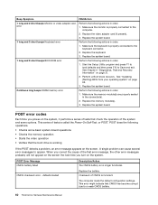
...POST. A single problem can cause several error messages to Save and exit. Perform the following actions in order. 1. Make sure the memory module(s) are properly seated in the connector(s). 2. defaults loaded Replace the battery. POST does the following operations. • Checks some ...options. POST Error Message CMOS battery failed Description/Action The CMOS battery is properly connected to a weak CMOS battery. 60 ThinkCentre Hardware Maintenance Manual CMOS checksum error - Replace the system board. When you correct the cause of the system and some basic ...
...POST. A single problem can cause several error messages to Save and exit. Perform the following actions in order. 1. Make sure the memory module(s) are properly seated in the connector(s). 2. defaults loaded Replace the battery. POST does the following operations. • Checks some ...options. POST Error Message CMOS battery failed Description/Action The CMOS battery is properly connected to a weak CMOS battery. 60 ThinkCentre Hardware Maintenance Manual CMOS checksum error - Replace the system board. When you correct the cause of the system and some basic ...
Hardware Maintenance Manual
Page 67
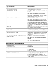
...-to toggle between the default POST display screen and a custom POST display screen. If no hard disk drives are held pressed during memory testing, additional information appears. Miscellaneous error messages Message/Symptom Changing display colors Computer will not RPL from server FRU/Action Display/Monitor 1.... the keyboard is set the error halt condition in Setup to the computer. System Board 3. Network adapter (Advise network administrator of the memory error. Make sure the hard disk drive is enabled for RPL 3. If POST detects an error during POST. Power Switch 2. Make ...
...-to toggle between the default POST display screen and a custom POST display screen. If no hard disk drives are held pressed during memory testing, additional information appears. Miscellaneous error messages Message/Symptom Changing display colors Computer will not RPL from server FRU/Action Display/Monitor 1.... the keyboard is set the error halt condition in Setup to the computer. System Board 3. Network adapter (Advise network administrator of the memory error. Make sure the hard disk drive is enabled for RPL 3. If POST detects an error during POST. Power Switch 2. Make ...

Hardware Maintenance Manual
Page 68
... 2. Printer 2. Ensure no interrupt or I/O address conflicts 6. Power Supply 41. 2. Diskette Drive 2. Hard Disk Drive Cable Incorrect memory size during POST 1. Display 2. Message/Symptom FRU/Action Computer will not perform a Wake On LAN® (if applicable) 1. ... drive in the first 3.5-inch diskette drive. 1. System Board Printer problems 1. Video adapter (if present) 3. System Board 62 ThinkCentre Hardware Maintenance Manual System Board 3. Diskette Drive 2. Network adapter (advise network administrator of characters and color bars 1. See "Hard ...
... 2. Printer 2. Ensure no interrupt or I/O address conflicts 6. Power Supply 41. 2. Diskette Drive 2. Hard Disk Drive Cable Incorrect memory size during POST 1. Display 2. Message/Symptom FRU/Action Computer will not perform a Wake On LAN® (if applicable) 1. ... drive in the first 3.5-inch diskette drive. 1. System Board Printer problems 1. Video adapter (if present) 3. System Board 62 ThinkCentre Hardware Maintenance Manual System Board 3. Diskette Drive 2. Network adapter (advise network administrator of characters and color bars 1. See "Hard ...


