User Manual
Page 5
... 128 Locating parts on the system board 89 Removing and reinstalling the front bezel . . . . 89 Installing or replacing a memory module . . . . 90 Installing or replacing a PCI card 92 Replacing the battery 95 Replacing the power supply assembly . ...53 Selecting a temporary startup device . . . . . 53 Viewing or changing the startup device sequence 54 Exiting the Setup Utility program 54 © Copyright Lenovo 2009 Chapter 7. About this manual . . . . . 1 Important safety information 1 Important information about replacing the RoHS compliant FRUs 2 Chapter 2. Safety information...
... 128 Locating parts on the system board 89 Removing and reinstalling the front bezel . . . . 89 Installing or replacing a memory module . . . . 90 Installing or replacing a PCI card 92 Replacing the battery 95 Replacing the power supply assembly . ...53 Selecting a temporary startup device . . . . . 53 Viewing or changing the startup device sequence 54 Exiting the Setup Utility program 54 © Copyright Lenovo 2009 Chapter 7. About this manual . . . . . 1 Important safety information 1 Important information about replacing the RoHS compliant FRUs 2 Chapter 2. Safety information...
User Manual
Page 62
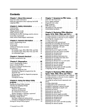
... from a disc" on page 278 2. Flash the system. System board 1. Run Setup 2. See "Updating (flashing) BIOS from a disc" on page 278 2. Reboot the system 2. Run memory test 4. System board 1. See "Updating (flashing) BIOS from a disc" on page 278 2. Flash the system. See "Updating (flashing) BIOS from a disc" on page 278 3.
... from a disc" on page 278 2. Flash the system. System board 1. Run Setup 2. See "Updating (flashing) BIOS from a disc" on page 278 2. Reboot the system 2. Run memory test 4. System board 1. See "Updating (flashing) BIOS from a disc" on page 278 2. Flash the system. See "Updating (flashing) BIOS from a disc" on page 278 3.

User Manual
Page 64
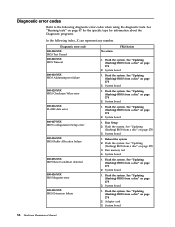
... called out is called out in warning statement 4. Flash the system. Make sure the component that is connected and/or enabled. Flash the system. Run memory test 4. System board 1. System board 1. System board System board System board 1. System board 1. See Chapter 6, "Using the Setup Utility program," on system and re-test...
... called out is called out in warning statement 4. Flash the system. Make sure the component that is connected and/or enabled. Flash the system. Run memory test 4. System board 1. System board 1. System board System board System board 1. System board 1. See Chapter 6, "Using the Setup Utility program," on system and re-test...

User Manual
Page 71
System board 1. Run memory test 4. System board 1. Flash the system. Symptom-to review the log file 2. System board 1. Remove USB device(s) and re-test 2. Flash the system and re-...
System board 1. Run memory test 4. System board 1. Flash the system. Symptom-to review the log file 2. System board 1. Remove USB device(s) and re-test 2. Flash the system and re-...

User Manual
Page 81
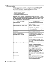
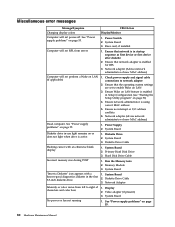
...Asset Security Test Passed 185-XXX-XXX Asset Security failure 185-278-XXX Asset Security Chassis Intrusion 201-000-XXX System Memory Test Passed 201-XXX-XXX System Memory error 202-000-XXX System Cache Test Passed 202-XXX-XXX System Cache error 206-000-XXX Diskette Drive Test ... Drive Test Passed FRU/Action 1. Flash the system and re-test. System board 1. Assure Asset Security Enabled 2. C2 Cover Switch 3. Replace the memory module called out, make sure it is called out by the test 2. Cache, if removable 2. Diskette Drive Cable 2. System board No action Chapter 7.
...Asset Security Test Passed 185-XXX-XXX Asset Security failure 185-278-XXX Asset Security Chassis Intrusion 201-000-XXX System Memory Test Passed 201-XXX-XXX System Memory error 202-000-XXX System Cache Test Passed 202-XXX-XXX System Cache error 206-000-XXX Diskette Drive Test ... Drive Test Passed FRU/Action 1. Flash the system and re-test. System board 1. Assure Asset Security Enabled 2. C2 Cover Switch 3. Replace the memory module called out, make sure it is called out by the test 2. Cache, if removable 2. Diskette Drive Cable 2. System board No action Chapter 7.

User Manual
Page 83
...on page 278. Start the Setup Utility program and press F7 to load defaults and then press F10 to Save and exit. Make sure the memory module(s) are tones or a series of tones separated by pauses (intervals without sound) during POST. The following tables describes beep symptoms. Beep ...Monitor or video adapter card error 1 long and 3 short beeps Keyboard error 1 long and 9 short beeps BIOS ROM error Continuos long beeps DRAM memory error FRU/Action Perform the following actions in order. 1. Start the Setup Utility program and press F10 to Save and exit. Perform the following ...
...on page 278. Start the Setup Utility program and press F7 to load defaults and then press F10 to Save and exit. Make sure the memory module(s) are tones or a series of tones separated by pauses (intervals without sound) during POST. The following tables describes beep symptoms. Beep ...Monitor or video adapter card error 1 long and 3 short beeps Keyboard error 1 long and 9 short beeps BIOS ROM error Continuos long beeps DRAM memory error FRU/Action Perform the following actions in order. 1. Start the Setup Utility program and press F10 to Save and exit. Perform the following ...
User Manual
Page 84
...Verifies that the boot drive is no longer functional. Make sure the hard disk drive is incorrect. The BIOS then ignores the missing keyboard during memory testing, additional information appears. If POST detects an error during POST. v Checks some options. When you correct the cause of the first error... halt condition in Setup is properly connected to HALT ON ALL, BUT KEYBOARD. This series of tests is the running speed of the memory error. 78 Hardware Maintenance Manual POST error codes Each time you turn on the system. This information gives specifics about the type and...
...Verifies that the boot drive is no longer functional. Make sure the hard disk drive is incorrect. The BIOS then ignores the missing keyboard during memory testing, additional information appears. If POST detects an error during POST. v Checks some options. When you correct the cause of the first error... halt condition in Setup is properly connected to HALT ON ALL, BUT KEYBOARD. This series of tests is the running speed of the memory error. 78 Hardware Maintenance Manual POST error codes Each time you turn on the system. This information gives specifics about the type and...
User Manual
Page 86
...55. System Board 3. Power Supply 2. See "Power supply problems" on page 51) 4. Incorrect memory size during POST ″Insert a Diskette″ icon appears with an otherwise blank display. Memory Module 3. Diskette Drive Cable 3. Ensure that network is enabled in the first 3.5-inch diskette drive...sequence as first device or first device after diskette 2. Intensity or color varies from server Computer will not power-off. Run the Memory tests 2. System Board 1. System Board 3. See "Power supply problems" on or does not light when drive is using correct ...
...55. System Board 3. Power Supply 2. See "Power supply problems" on page 51) 4. Incorrect memory size during POST ″Insert a Diskette″ icon appears with an otherwise blank display. Memory Module 3. Diskette Drive Cable 3. Ensure that network is enabled in the first 3.5-inch diskette drive...sequence as first device or first device after diskette 2. Intensity or color varies from server Computer will not power-off. Run the Memory tests 2. System Board 1. System Board 3. See "Power supply problems" on or does not light when drive is using correct ...

User Manual
Page 88
Power-on the computer to re-test the system. 4. Hard disk drive h. External Cache f. If all devices and adapters have been removed, and the problem continues, replace the system board. 82 Hardware Maintenance Manual Memory modules d. External Cache RAM g. c. Repeat steps 1 through 3 until you find the failing device or adapter. Extended video memory e. Diskette drive 3.
Power-on the computer to re-test the system. 4. Hard disk drive h. External Cache f. If all devices and adapters have been removed, and the problem continues, replace the system board. 82 Hardware Maintenance Manual Memory modules d. External Cache RAM g. c. Repeat steps 1 through 3 until you find the failing device or adapter. Extended video memory e. Diskette drive 3.

User Manual
Page 94
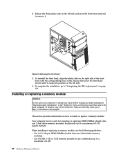
Figure 4 shows the locations of the various components in your computer. Component locations 1 Heat sink and fan assembly 2 Memory modules 3 Battery 4 PCI Express x16 graphics card slot 5 PCI card 6 PCI card slot 7 PCI Express x1 card slot 8 Cover presence switch (Intrusion switch) (some models) 9 Rear fan assembly 10 Power supply assembly 88 Hardware Maintenance Manual Figure 4. Locating components To remove the computer cover, see "Removing the computer cover" on page 86.
Figure 4 shows the locations of the various components in your computer. Component locations 1 Heat sink and fan assembly 2 Memory modules 3 Battery 4 PCI Express x16 graphics card slot 5 PCI card 6 PCI card slot 7 PCI Express x1 card slot 8 Cover presence switch (Intrusion switch) (some models) 9 Rear fan assembly 10 Power supply assembly 88 Hardware Maintenance Manual Figure 4. Locating components To remove the computer cover, see "Removing the computer cover" on page 86.

User Manual
Page 95
... and reinstall the front bezel, do the following: 1. Tamdhu 89 Replacing FRUs - Chapter 8. Remove the computer cover. System board parts locations 1 Microprocessor 2 Microprocessor fan connector 3 Memory slots (2) 4 Thermal sensor connector 5 Diskette drive connector 6 24-pin power connector 7 Battery 8 Cover presence (Intrusion) switch connector 9 SATA connectors (4) 10 Clear CMOS (Complementary Metal Oxide...
... and reinstall the front bezel, do the following: 1. Tamdhu 89 Replacing FRUs - Chapter 8. Remove the computer cover. System board parts locations 1 Microprocessor 2 Microprocessor fan connector 3 Memory slots (2) 4 Thermal sensor connector 5 Diskette drive connector 6 24-pin power connector 7 Battery 8 Cover presence (Intrusion) switch connector 9 SATA connectors (4) 10 Clear CMOS (Complementary Metal Oxide...
User Manual
Page 96
... it. Removing the front bezel 3. 2. When installing or replacing a memory module, use the following guidelines: v Use 1.8 V, 240-pin, DDR2 DIMMs (double data rate 2 dual inline memory modules). To obtain a copy of the ThinkCentre Safety and Warranty Guide, go to "Completing the FRU replacement" on...of 4 GB system memory. Your computer has two slots for installing or replacing DDR2 DIMMs (double data rate 2 dual inline memory modules) that came with the corresponding holes in the ThinkCentre Safety and Warranty Guide that provide up to : http://www.lenovo.com/support This section ...
... it. Removing the front bezel 3. 2. When installing or replacing a memory module, use the following guidelines: v Use 1.8 V, 240-pin, DDR2 DIMMs (double data rate 2 dual inline memory modules). To obtain a copy of the ThinkCentre Safety and Warranty Guide, go to "Completing the FRU replacement" on...of 4 GB system memory. Your computer has two slots for installing or replacing DDR2 DIMMs (double data rate 2 dual inline memory modules) that came with the corresponding holes in the ThinkCentre Safety and Warranty Guide that provide up to : http://www.lenovo.com/support This section ...

User Manual
Page 97
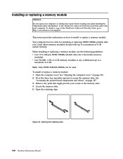
... might prevent access to the memory slots. 3. Remove the computer cover. See "Locating parts on the system board" on page 86. 2. Opening the retaining clips If you are replacing an old memory module, open the retaining clips and remove the memory module being replaced as shown.... Replacing FRUs - To install or replace a memory module, do the following: 1. Removing the memory module Chapter 8. See "Removing the computer cover" on page ...
... might prevent access to the memory slots. 3. Remove the computer cover. See "Locating parts on the system board" on page 86. 2. Opening the retaining clips If you are replacing an old memory module, open the retaining clips and remove the memory module being replaced as shown.... Replacing FRUs - To install or replace a memory module, do the following: 1. Removing the memory module Chapter 8. See "Removing the computer cover" on page ...

User Manual
Page 98
Installing the memory module What to do next: v To work with another piece of the ThinkCentre Safety and Warranty Guide, go to: http://www.lenovo.com/support This section provides instructions on how to install or replace a PCI card. To obtain a copy of hardware, go to the appropriate ... replacing a PCI card Attention Do not open your computer or attempt any repair before reading and understanding the "Important safety information" in the ThinkCentre Safety and Warranty Guide that the notch 1 on the memory module aligns correctly with your computer. Figure 9. 5. Position the...
Installing the memory module What to do next: v To work with another piece of the ThinkCentre Safety and Warranty Guide, go to: http://www.lenovo.com/support This section provides instructions on how to install or replace a PCI card. To obtain a copy of hardware, go to the appropriate ... replacing a PCI card Attention Do not open your computer or attempt any repair before reading and understanding the "Important safety information" in the ThinkCentre Safety and Warranty Guide that the notch 1 on the memory module aligns correctly with your computer. Figure 9. 5. Position the...

User Manual
Page 101
... forever. 5. Replacing FRUs - To obtain a copy of memory that maintains the date, time, and settings for built-in the ThinkCentre Safety and Warranty Guide that came with another piece of hardware, go to : http://www.lenovo.com/support Your computer has a special type of the ThinkCentre Safety and Warranty Guide, go to secure the...
... forever. 5. Replacing FRUs - To obtain a copy of memory that maintains the date, time, and settings for built-in the ThinkCentre Safety and Warranty Guide that came with another piece of hardware, go to : http://www.lenovo.com/support Your computer has a special type of the ThinkCentre Safety and Warranty Guide, go to secure the...

User Manual
Page 109
... microprocessor socket cover from the failing system board. To obtain a copy of the chassis. 9. Remove all the cables. See "Installing or replacing a memory module" on page 90 and "Installing or replacing a PCI card" on page 86. 2. Remove the heat sink and fan assembly from the new system..." on page 92. 5. Lay the computer on page 89. 6. Carefully move the system board out of the ThinkCentre Safety and Warranty Guide, go to: http://www.lenovo.com/support This section provides instructions on the failing system board. Remove the screws that came with the hard disk drive...
... microprocessor socket cover from the failing system board. To obtain a copy of the chassis. 9. Remove all the cables. See "Installing or replacing a memory module" on page 90 and "Installing or replacing a PCI card" on page 86. 2. Remove the heat sink and fan assembly from the new system..." on page 92. 5. Lay the computer on page 89. 6. Carefully move the system board out of the ThinkCentre Safety and Warranty Guide, go to: http://www.lenovo.com/support This section provides instructions on the failing system board. Remove the screws that came with the hard disk drive...

User Manual
Page 110
... and fan assembly and connect the heat sink and fan assembly cable to "Completing the FRU replacement" on the new system board. 16. Reconnect all memory modules and adapter cards removed from the microprocessor socket, and then close the microprocessor retainer and lock it into position with the small handle. To...
... and fan assembly and connect the heat sink and fan assembly cable to "Completing the FRU replacement" on the new system board. 16. Reconnect all memory modules and adapter cards removed from the microprocessor socket, and then close the microprocessor retainer and lock it into position with the small handle. To...

User Manual
Page 134
Component locations 1 Hard disk drive 2 Heat sink and fan assembly 3 Internal speaker 4 Optical drive 5 Memory slots 6 Power supply assembly 128 Hardware Maintenance Manual Locating components To open the computer cover, see "Opening the computer cover" on page 126. Figure 43. Figure 43 shows the location of the various components in your computer.
Component locations 1 Hard disk drive 2 Heat sink and fan assembly 3 Internal speaker 4 Optical drive 5 Memory slots 6 Power supply assembly 128 Hardware Maintenance Manual Locating components To open the computer cover, see "Opening the computer cover" on page 126. Figure 43. Figure 43 shows the location of the various components in your computer.

User Manual
Page 135
... slot 3 Internal speaker connector 4 Battery 5 Microprocessor fan connector 6 Thermal sensor connector 7 Cover presence (Intrusion) switch connector 8 Microprocessor 9 4-pin power connector 10 Front panel connector 11 Memory slots (2) 12 Front USB connectors (2) 13 Serial (COM 2) connector 14 Power fan connector 15 24-pin power connector 16 SATA connectors (2) 17 Clear CMOS (Complementary...
... slot 3 Internal speaker connector 4 Battery 5 Microprocessor fan connector 6 Thermal sensor connector 7 Cover presence (Intrusion) switch connector 8 Microprocessor 9 4-pin power connector 10 Front panel connector 11 Memory slots (2) 12 Front USB connectors (2) 13 Serial (COM 2) connector 14 Power fan connector 15 24-pin power connector 16 SATA connectors (2) 17 Clear CMOS (Complementary...
User Manual
Page 136
... has two slots for installing or replacing DDR2 DIMMs (double data rate 2 dual inline memory modules) that might prevent your computer. Pivot the drive bay assembly upward to a maximum of the ThinkCentre Safety and Warranty Guide, go to: http://www.lenovo.com/support This section provides instructions on how to install or replace...
... has two slots for installing or replacing DDR2 DIMMs (double data rate 2 dual inline memory modules) that might prevent your computer. Pivot the drive bay assembly upward to a maximum of the ThinkCentre Safety and Warranty Guide, go to: http://www.lenovo.com/support This section provides instructions on how to install or replace...


