
Hardware Maintenance Manual
Page 5
... Replacing the hard disk drive 112 Replacing an optical drive 114 Replacing the diskette drive 115 Replacing the power switch/LED assembly . . . 116 Replacing the front panel card 117 Replacing the system fan assembly 117 Replacing a PCI adapter 119 Completing the FRU replacement 120... 46 Running diagnostics from the Setup Utility program . . . . . 54 © Lenovo 2005, 2008. Contents Chapter 1. About this manual . . . . . 1 Important Safety Information 1 Important information about replacing RoHS compliant FRUs 2 Chapter 2. Safety information . . . . . 3 General safety ...
... Replacing the hard disk drive 112 Replacing an optical drive 114 Replacing the diskette drive 115 Replacing the power switch/LED assembly . . . 116 Replacing the front panel card 117 Replacing the system fan assembly 117 Replacing a PCI adapter 119 Completing the FRU replacement 120... 46 Running diagnostics from the Setup Utility program . . . . . 54 © Lenovo 2005, 2008. Contents Chapter 1. About this manual . . . . . 1 Important Safety Information 1 Important information about replacing RoHS compliant FRUs 2 Chapter 2. Safety information . . . . . 3 General safety ...
Hardware Maintenance Manual
Page 6
... switch/LED assembly . . Replacing a memory module Replacing a PCI adapter Replacing the hard disk drive Replacing an optical drive Replacing the diskette drive Replacing the rear fan assembly Replacing the front fan assembly Replacing the front audio/USB assembly . . . Replacing the CMOS battery Completing the FRU replacement . . . . . . 139 . 142 . 146 . 148 . 150 . 153 . 154 . 155 . 157 . 159 . 160 . 160 . 161 Chapter 10. FRU lists 163...
... switch/LED assembly . . Replacing a memory module Replacing a PCI adapter Replacing the hard disk drive Replacing an optical drive Replacing the diskette drive Replacing the rear fan assembly Replacing the front fan assembly Replacing the front audio/USB assembly . . . Replacing the CMOS battery Completing the FRU replacement . . . . . . 139 . 142 . 146 . 148 . 150 . 153 . 154 . 155 . 157 . 159 . 160 . 160 . 161 Chapter 10. FRU lists 163...

Hardware Maintenance Manual
Page 49
... cause false errors and unnecessary replacement of hardware and software combinations that software package. v Machine type and model v Processor or hard disk upgrades v Failure symptom - Portions © IBM Corp. 2005. 43 General Checkout Attention The drives in problem determination. Check all...external devices. 2. Power-on page 78. Problem determination tips Due to the middle position. 4. Do diagnostics indicate a failure? © Lenovo 2005, 2008. Chapter 4. Set all cables and power cords. 3. Look at step 7. 7. If you do receive the correct response,...
... cause false errors and unnecessary replacement of hardware and software combinations that software package. v Machine type and model v Processor or hard disk upgrades v Failure symptom - Portions © IBM Corp. 2005. 43 General Checkout Attention The drives in problem determination. Check all...external devices. 2. Power-on page 78. Problem determination tips Due to the middle position. 4. Do diagnostics indicate a failure? © Lenovo 2005, 2008. Chapter 4. Set all cables and power cords. 3. Look at step 7. 7. If you do receive the correct response,...
Hardware Maintenance Manual
Page 61
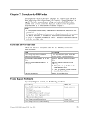
...switch for proper installation. Portions © IBM Corp. 2005. 55 No operating system installed on Switch © Lenovo 2005, 2008. The drive is listed first. The drive must be used to have the following procedures. v Power Cord v On/Off Switch connector v On/Off Switch ... v Microprocessor(s) connection Check the power cord for a description of this index, go to "Undetermined problems" on the failing hard disk drive. 2. Replace the hard disk drive. v If you decide which FRUs to help you did receive a POST error message, diagnose the POST error message first....
...switch for proper installation. Portions © IBM Corp. 2005. 55 No operating system installed on Switch © Lenovo 2005, 2008. The drive is listed first. The drive must be used to have the following procedures. v Power Cord v On/Off Switch connector v On/Off Switch ... v Microprocessor(s) connection Check the power cord for a description of this index, go to "Undetermined problems" on the failing hard disk drive. 2. Replace the hard disk drive. v If you decide which FRUs to help you did receive a POST error message, diagnose the POST error message first....
Hardware Maintenance Manual
Page 84
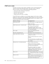
...78 Hardware Maintenance Manual A single problem can cause several error messages to HALT ON ALL, BUT KEYBOARD. defaults loaded Replace the battery. Make sure the hard disk drive is working If the POST detects a problem, an error message appears on the screen. Memory Test: Memory test fail... nnnn is the running speed of tests is incorrect. Pressing Esc skips the full memory test Cannot find or initialize the hard disk drive controller or the drive. POST does the following operations. The BIOS then ignores the missing keyboard during a full memory test, counting down the...
...78 Hardware Maintenance Manual A single problem can cause several error messages to HALT ON ALL, BUT KEYBOARD. defaults loaded Replace the battery. Make sure the hard disk drive is working If the POST detects a problem, an error message appears on the screen. Memory Test: Memory test fail... nnnn is the running speed of tests is incorrect. Pressing Esc skips the full memory test Cannot find or initialize the hard disk drive controller or the drive. POST does the following operations. The BIOS then ignores the missing keyboard during a full memory test, counting down the...
Hardware Maintenance Manual
Page 88
Power-on the computer to re-test the system. 4. Extended video memory e. External Cache RAM g. If all devices and adapters have been removed, and the problem continues, replace the system board. 82 Hardware Maintenance Manual c. External Cache f. Diskette drive 3. Hard disk drive h. Memory modules d. Repeat steps 1 through 3 until you find the failing device or adapter.
Power-on the computer to re-test the system. 4. Extended video memory e. External Cache RAM g. If all devices and adapters have been removed, and the problem continues, replace the system board. 82 Hardware Maintenance Manual c. External Cache f. Diskette drive 3. Hard disk drive h. Memory modules d. Repeat steps 1 through 3 until you find the failing device or adapter.
Hardware Maintenance Manual
Page 101
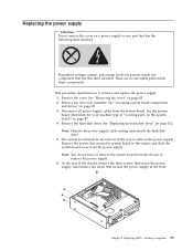
... the system board" on page 87. 4. Note: Observe the power supply cable routing underneath the hard disk drive. 5. Desktop computers 95 There are present inside these components. See "Replacing the hard disk drive" on page 112. Remove the drive bay assembly. Replacing the power supply Attention Never remove the cover on a power supply or any component that...
... the system board" on page 87. 4. Note: Observe the power supply cable routing underneath the hard disk drive. 5. Desktop computers 95 There are present inside these components. See "Replacing the hard disk drive" on page 112. Remove the drive bay assembly. Replacing the power supply Attention Never remove the cover on a power supply or any component that...
Hardware Maintenance Manual
Page 102
...that the screws holes are properly aligned and install the system board screws. 11. Reinstall the front bezel. 16. Install the hard disk drive. Align the drive bay assembly studs with the two slots on the sides of the chassis until it into position. 15. v If the voltage... were disconnected. 14. Route the power supply cable through the cable clamps underneath the hard disk drive and reconnect all power supply cables to "Completing the FRU replacement" on page 112. 13. See "Replacing the hard disk drive" on page 120. 96 Hardware Maintenance Manual v If the voltage supply range in...
...that the screws holes are properly aligned and install the system board screws. 11. Reinstall the front bezel. 16. Install the hard disk drive. Align the drive bay assembly studs with the two slots on the sides of the chassis until it into position. 15. v If the voltage... were disconnected. 14. Route the power supply cable through the cable clamps underneath the hard disk drive and reconnect all power supply cables to "Completing the FRU replacement" on page 112. 13. See "Replacing the hard disk drive" on page 120. 96 Hardware Maintenance Manual v If the voltage supply range in...
Hardware Maintenance Manual
Page 103
... to release the heat sink clamp and then disengage the clamp from the system board. The procedure varies depending upon the machine type. See "Replacing the hard disk drive" on page 90. 5. See "Removing the cover" on the new system board. 10. Disconnect the heat sink and fan assembly cable from the plastic...
... to release the heat sink clamp and then disengage the clamp from the system board. The procedure varies depending upon the machine type. See "Replacing the hard disk drive" on page 90. 5. See "Removing the cover" on the new system board. 10. Disconnect the heat sink and fan assembly cable from the plastic...
Hardware Maintenance Manual
Page 105
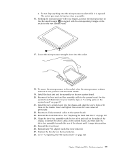
Install the new system board into the socket. 18. Insert and tighten the screws the were removed previously. 22. See "Replacing the hard disk drive" on the heat sink fan. 28. Go to the system board. 23. Lower the microprocessor straight down into the chassis and align the screw... holes with your machine type at "Locating parts on the system board" on page 120. Reinstall the hard disk drive. Reinstall the front bezel. 26. Position the fan duct on page 112. 24. Holding the microprocessor with those in the chassis. Install the...
Install the new system board into the socket. 18. Insert and tighten the screws the were removed previously. 22. See "Replacing the hard disk drive" on the heat sink fan. 28. Go to the system board. 23. Lower the microprocessor straight down into the chassis and align the screw... holes with your machine type at "Locating parts on the system board" on page 120. Reinstall the hard disk drive. Reinstall the front bezel. 26. Position the fan duct on page 112. 24. Holding the microprocessor with those in the chassis. Install the...

Hardware Maintenance Manual
Page 106
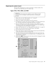
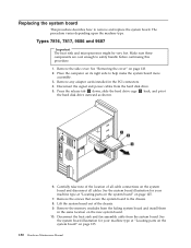
... contact with this procedure. See the system board illustration for the new system board. See "Accessing system board components and drives" on page 112. 7. See "Replacing the hard disk drive" on page 90. 5. Types 7814, 7815, 9682, 9683, 9684, and 9685 Important The heat sink and microprocessor ... order a new retention module for your machine type at "Locating parts on the system board" on page 87. 6. Remove the hard disk drive. Lift the fan duct off the failing system board. See the system board illustration for the new system board before continuing this procedure...
... contact with this procedure. See the system board illustration for the new system board. See "Accessing system board components and drives" on page 112. 7. See "Replacing the hard disk drive" on page 90. 5. Types 7814, 7815, 9682, 9683, 9684, and 9685 Important The heat sink and microprocessor ... order a new retention module for your machine type at "Locating parts on the system board" on page 87. 6. Remove the hard disk drive. Lift the fan duct off the failing system board. See the system board illustration for the new system board before continuing this procedure...
Hardware Maintenance Manual
Page 109
...system board. 23. Insert and tighten the screws that were disconnected from the system board. 24. Reinstall the front bezel. 27. Replacing FRUs - Reinstall the hard disk drive. Position the fan duct on page 87. 22. Chapter 8. Install the new system board into position. 26. Desktop computers 103 See... with those in the chassis. Reinstall any PCI adapter cards that were removed. 28. 21. See "Replacing the hard disk drive" on the system board, and then slide the drive bay assembly towards the rear of the chassis until it snaps into the chassis and align the screw holes...
...system board. 23. Insert and tighten the screws that were disconnected from the system board. 24. Reinstall the front bezel. 27. Replacing FRUs - Reinstall the hard disk drive. Position the fan duct on page 87. 22. Chapter 8. Install the new system board into position. 26. Desktop computers 103 See... with those in the chassis. Reinstall any PCI adapter cards that were removed. 28. 21. See "Replacing the hard disk drive" on the system board, and then slide the drive bay assembly towards the rear of the chassis until it snaps into the chassis and align the screw holes...
Hardware Maintenance Manual
Page 118
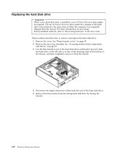
... Recovery discs might be restored to be required. Use the blue handle to pivot the hard disk drive and bracket upward, slide the hard drive to the left until it from the chassis. 4. Replacing the hard disk drive Important When a new hard disk drive is free of the retaining clips in the User Guide. Disconnect the signal and power...
... Recovery discs might be restored to be required. Use the blue handle to pivot the hard disk drive and bracket upward, slide the hard drive to the left until it from the chassis. 4. Replacing the hard disk drive Important When a new hard disk drive is free of the retaining clips in the User Guide. Disconnect the signal and power...
Hardware Maintenance Manual
Page 119
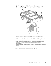
... chassis and reconnect the diskette drive and optical drive cables (if disconnected). 11. Slide the hard disk drive and bracket to "Completing the FRU replacement" on each side of the hard disk drive. 7. Reinstall the front bezel. 13. Replacing FRUs - Slide the drive bay assembly towards the rear of the hard disk drive. 8. Position the hard disk drive and bracket so that it...
... chassis and reconnect the diskette drive and optical drive cables (if disconnected). 11. Slide the hard disk drive and bracket to "Completing the FRU replacement" on each side of the hard disk drive. 7. Reinstall the front bezel. 13. Replacing FRUs - Slide the drive bay assembly towards the rear of the hard disk drive. 8. Position the hard disk drive and bracket so that it...

Hardware Maintenance Manual
Page 122
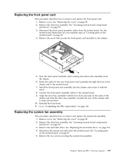
...routing and remove the assembly from the system board. Align the drive bay assembly with the two slots and rails on page 120. 116 Hardware Maintenance Manual See "Replacing the hard disk drive" on page 85. 2. Replacing the power switch/LED assembly This procedure describes how to "Completing... the FRU replacement" on the sides of the chassis slide the drive bay assembly towards the rear of the chassis until...
...routing and remove the assembly from the system board. Align the drive bay assembly with the two slots and rails on page 120. 116 Hardware Maintenance Manual See "Replacing the hard disk drive" on page 85. 2. Replacing the power switch/LED assembly This procedure describes how to "Completing... the FRU replacement" on the sides of the chassis slide the drive bay assembly towards the rear of the chassis until...
Hardware Maintenance Manual
Page 123
...assembly through the hole in the chassis and to "Completing the FRU replacement" on page 85. 2. Remove the drive bay assembly. Disconnect the system fan cable from the system board. Replacing FRUs - See "Replacing the hard disk drive" on page 87. 4. Reinstall the front bezel. 11. See... "Accessing system board components and drives" on page 90. 3. Remove the hard disk drive. Install the front panel card assembly into the ...
...assembly through the hole in the chassis and to "Completing the FRU replacement" on page 85. 2. Remove the drive bay assembly. Disconnect the system fan cable from the system board. Replacing FRUs - See "Replacing the hard disk drive" on page 87. 4. Reinstall the front bezel. 11. See... "Accessing system board components and drives" on page 90. 3. Remove the hard disk drive. Install the front panel card assembly into the ...

Hardware Maintenance Manual
Page 124
.... 12. Go to "Completing the FRU replacement" on the system board. 9. Remove the system fan assembly by pulling the bracket outward and lifting it snaps into position. 11. Connect the system fan cable to remove completely. 7. See "Replacing the hard disk drive" on the sides of the chassis and ...slide the drive bay assembly towards the rear of the chassis until it up from the system board to the system fan...
.... 12. Go to "Completing the FRU replacement" on the system board. 9. Remove the system fan assembly by pulling the bracket outward and lifting it snaps into position. 11. Connect the system fan cable to remove completely. 7. See "Replacing the hard disk drive" on the sides of the chassis and ...slide the drive bay assembly towards the rear of the chassis until it up from the system board to the system fan...
Hardware Maintenance Manual
Page 136
...on the system board and disconnect all cable connections on its right side to remove and replace the system board. Press the release tab 1 down, slide the hard drive cage 2 back, and pivot the hard disk drive outward as shown. 6. The procedure varies depending upon the machine type. Remove any adapter...the location of the chassis. 9. Lift the system board out of all cables. Disconnect the heat sink and fan assembly cable from the hard disk drive. 5. See the system board illustration for your machine type at "Locating parts on the system board" on the new system board. 10....
...on the system board and disconnect all cable connections on its right side to remove and replace the system board. Press the release tab 1 down, slide the hard drive cage 2 back, and pivot the hard disk drive outward as shown. 6. The procedure varies depending upon the machine type. Remove any adapter...the location of the chassis. 9. Lift the system board out of all cables. Disconnect the heat sink and fan assembly cable from the hard disk drive. 5. See the system board illustration for your machine type at "Locating parts on the system board" on the new system board. 10....
Hardware Maintenance Manual
Page 140
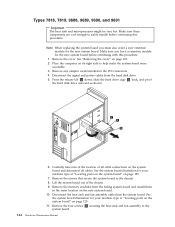
...on its right side to safely handle before continuing with this procedure. Carefully take note of the location of the chassis. 9. Note: When replacing the system board you have a retention module for your machine type at "Locating parts on the system board" on page 123. 2. ... board illustration for the new system board. Press the release tab 1 down, slide the hard drive cage 2 back, and pivot the hard disk drive outward as shown. 6. Disconnect the signal and power cables from the hard disk drive. 5. Types 7818, 7819, 9688, 9689, 9690, and 9691 Important The heat sink ...
...on its right side to safely handle before continuing with this procedure. Carefully take note of the location of the chassis. 9. Note: When replacing the system board you have a retention module for your machine type at "Locating parts on the system board" on page 123. 2. ... board illustration for the new system board. Press the release tab 1 down, slide the hard drive cage 2 back, and pivot the hard disk drive outward as shown. 6. Disconnect the signal and power cables from the hard disk drive. 5. Types 7818, 7819, 9688, 9689, 9690, and 9691 Important The heat sink ...
Hardware Maintenance Manual
Page 156
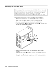
...power cables from the factory. Pull on recovering factory-installed software, refer to remove hard disk drive from the drive cage. 6. Replacing the hard disk drive Important When a new hard disk drive is installed, a set of Product Recovery discs enable the contents of Product Recovery discs..., slide the hard drive cage 2 back, and pivot the hard disk drive outward as when the computer was originally shipped from the hard disk drive. 3. Remove the failing hard disk drive from the blue plastic bracket from by simply sliding it helps to remove and replace the hard disk drive. 1. See ...
...power cables from the factory. Pull on recovering factory-installed software, refer to remove hard disk drive from the drive cage. 6. Replacing the hard disk drive Important When a new hard disk drive is installed, a set of Product Recovery discs enable the contents of Product Recovery discs..., slide the hard drive cage 2 back, and pivot the hard disk drive outward as when the computer was originally shipped from the hard disk drive. 3. Remove the failing hard disk drive from the blue plastic bracket from by simply sliding it helps to remove and replace the hard disk drive. 1. See ...


