
Hardware Maintenance Manual
Page 5
...45 PC-Doctor for DOS 46 Creating a diagnostic CD image 46 Creating diagnostic diskettes 46 Running diagnostics from the Setup Utility program . . . . . 54 © Lenovo 2005, 2008. Replacing FRUs (Types 7816, 7817, 7818, 7819, 9686, 9687, 9688, 9689, 9690, and 9691) . . . . . 121 Rear connectors 122... . . . 88 Machine types 9684 and 9685 89 Accessing system board components and drives . . 90 Replacing a memory module 92 Replacing the CMOS battery 94 Replacing the power supply 95 Replacing the system board 97 Types 7812, 7813, 9680, and 9681 97 Types 7814, 7815, 9682, 9683, 9684...
...45 PC-Doctor for DOS 46 Creating a diagnostic CD image 46 Creating diagnostic diskettes 46 Running diagnostics from the Setup Utility program . . . . . 54 © Lenovo 2005, 2008. Replacing FRUs (Types 7816, 7817, 7818, 7819, 9686, 9687, 9688, 9689, 9690, and 9691) . . . . . 121 Rear connectors 122... . . . 88 Machine types 9684 and 9685 89 Accessing system board components and drives . . 90 Replacing a memory module 92 Replacing the CMOS battery 94 Replacing the power supply 95 Replacing the system board 97 Types 7812, 7813, 9680, and 9681 97 Types 7814, 7815, 9682, 9683, 9684...
Hardware Maintenance Manual
Page 6
... Machine Type 9687 207 Machine Type 9688 214 Machine Type 9689 220 Machine Type 9690 227 Machine Type 9691 236 Chapter 11. Replacing the CMOS battery Completing the FRU replacement . . . . . . 139 . 142 . 146 . 148 . 150 . 153 . 154 . 155 . 157 . 159 . 160 . 160 . 161 Chapter 10. Types 7816, 7817, 9686 and 9687...
... Machine Type 9687 207 Machine Type 9688 214 Machine Type 9689 220 Machine Type 9690 227 Machine Type 9691 236 Chapter 11. Replacing the CMOS battery Completing the FRU replacement . . . . . . 139 . 142 . 146 . 148 . 150 . 153 . 154 . 155 . 157 . 159 . 160 . 160 . 161 Chapter 10. Types 7816, 7817, 9686 and 9687...
Hardware Maintenance Manual
Page 13
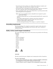
... power, telephone and communication cables is hazardous. Note: The use of the electrical outlet can use coax or connector-outside shells on a double-insulated or battery-operated system. v Connect all power cords to provide protection that meets the specific service requirement. Safety information 7 v Use the black side of this section are...
... power, telephone and communication cables is hazardous. Note: The use of the electrical outlet can use coax or connector-outside shells on a double-insulated or battery-operated system. v Connect all power cords to provide protection that meets the specific service requirement. Safety information 7 v Use the black side of this section are...
Hardware Maintenance Manual
Page 15
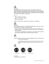
...installed, note the following : Laser radiation when open. Note the following : v Do not remove the covers. Removing the covers of the battery as CD-ROMs, DVD-ROM drives, fiber optic devices, or transmitters) are no serviceable parts inside the device. DANGER: Some laser products ... v Throw or immerse into the beam, do not view directly with the same module type made by the same manufacturer. Safety information 9 The battery contains lithium and can explode if not properly used, handled, or disposed of procedures other than 100°C (212°F) v Repair or disassemble...
...installed, note the following : Laser radiation when open. Note the following : v Do not remove the covers. Removing the covers of the battery as CD-ROMs, DVD-ROM drives, fiber optic devices, or transmitters) are no serviceable parts inside the device. DANGER: Some laser products ... v Throw or immerse into the beam, do not view directly with the same module type made by the same manufacturer. Safety information 9 The battery contains lithium and can explode if not properly used, handled, or disposed of procedures other than 100°C (212°F) v Repair or disassemble...
Hardware Maintenance Manual
Page 66
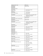
... board 1. System board 1. Video card, if installed 2. Video card, if installed 2. Video card, if installed 2. System board 1. Video card, if installed 4. CMOS Battery 2. System board System board System board 1. See "Flash update procedures" on page 243 2. Video card, if installed 2. Run Setup 2. System board 1. Video drivers update...XXX 001-287-XXX 001-288-XXX System Timer failure 001-292-XXX System CMOS RAM error 001-293-XXX System CMOS Battery 001-298-XXX System RTC date/time update failure 001-299-XXX System RTC periodic interrupt failure 001-300-XXX System RTC...
... board 1. System board 1. Video card, if installed 2. Video card, if installed 2. Video card, if installed 2. System board 1. Video card, if installed 4. CMOS Battery 2. System board System board System board 1. See "Flash update procedures" on page 243 2. Video card, if installed 2. Run Setup 2. System board 1. Video drivers update...XXX 001-287-XXX 001-288-XXX System Timer failure 001-292-XXX System CMOS RAM error 001-293-XXX System CMOS Battery 001-298-XXX System RTC date/time update failure 001-299-XXX System RTC periodic interrupt failure 001-300-XXX System RTC...
Hardware Maintenance Manual
Page 84
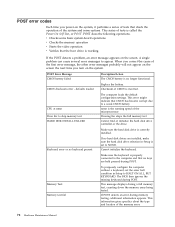
... time you power-on the system, it performs a series of tests that check the operation of the microprocessor. defaults loaded Replace the battery. Make sure the keyboard is working If the POST detects a problem, an error message appears on the system. This error might indicate... memory error. 78 Hardware Maintenance Manual A single problem can cause several error messages to NONE. POST Error Message CMOS battery failed Description/Action The CMOS battery is incorrect. Make sure the hard disk drive is set the error halt condition in Setup is correctly installed. Keyboard ...
... time you power-on the system, it performs a series of tests that check the operation of the microprocessor. defaults loaded Replace the battery. Make sure the keyboard is working If the POST detects a problem, an error message appears on the system. This error might indicate... memory error. 78 Hardware Maintenance Manual A single problem can cause several error messages to NONE. POST Error Message CMOS battery failed Description/Action The CMOS battery is incorrect. Make sure the hard disk drive is set the error halt condition in Setup is correctly installed. Keyboard ...
Hardware Maintenance Manual
Page 93
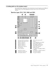
... connector 4 7 Diskette drive connector 8 IDE connector 9 Power connector 10 Power fan connector 11 SATA IDE connectors (4) 12 Front panel connector 13 Front USB connectors (2) 14 Battery 15 Clear CMOS/Recovery jumper 16 Serial (COM) connector 17 PCI adapter connectors (2) 18 Mono (speaker) connector 19 Front audio connector 20 CD-IN connector...
... connector 4 7 Diskette drive connector 8 IDE connector 9 Power connector 10 Power fan connector 11 SATA IDE connectors (4) 12 Front panel connector 13 Front USB connectors (2) 14 Battery 15 Clear CMOS/Recovery jumper 16 Serial (COM) connector 17 PCI adapter connectors (2) 18 Mono (speaker) connector 19 Front audio connector 20 CD-IN connector...
Hardware Maintenance Manual
Page 94
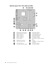
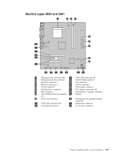
... fan connector 14 Front USB connectors (2) 15 Serial (COM) connector 16 Front audio connector 17 PCI adapter connector 18 PCI Express x1 adapter connectors (2) 19 Battery 20 PCI Express x16 graphics adapter connector 21 System fan connector 22 12v power connector 88 Hardware Maintenance Manual
... fan connector 14 Front USB connectors (2) 15 Serial (COM) connector 16 Front audio connector 17 PCI adapter connector 18 PCI Express x1 adapter connectors (2) 19 Battery 20 PCI Express x16 graphics adapter connector 21 System fan connector 22 12v power connector 88 Hardware Maintenance Manual

Hardware Maintenance Manual
Page 95
... connector 16 Front audio connector 6 Diskette drive connector 17 PCI adapter connectors (2) 7 IDE connector 18 PCI Express x1 adapter connector 8 Clear CMOS/Recovery jumpers 19 Battery (2) 9 Power fan connector 20 PCI Express x16 graphics adapter connector 10 SATA IDE connectors (4) 21 System fan connector 11 Front panel connector 22 12v power...
... connector 16 Front audio connector 6 Diskette drive connector 17 PCI adapter connectors (2) 7 IDE connector 18 PCI Express x1 adapter connector 8 Clear CMOS/Recovery jumpers 19 Battery (2) 9 Power fan connector 20 PCI Express x16 graphics adapter connector 10 SATA IDE connectors (4) 21 System fan connector 11 Front panel connector 22 12v power...
Hardware Maintenance Manual
Page 96
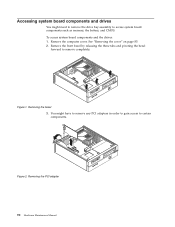
Remove the front bezel by releasing the three tabs and pivoting the bezel forward to remove completely. You might need to remove the drive bay assembly to access system board components such as memory, the battery, and CMOS. To access system board components and the drives: 1. Removing the bezel 3. Remove the computer cover. Figure 2. Removing the PCI adapter 90 Hardware Maintenance Manual Accessing system board components and drives You might have to remove any PCI adapters in order to gain access to certain components. See "Removing the cover" on page 85. 2. Figure 1.
Remove the front bezel by releasing the three tabs and pivoting the bezel forward to remove completely. You might need to remove the drive bay assembly to access system board components such as memory, the battery, and CMOS. To access system board components and the drives: 1. Removing the bezel 3. Remove the computer cover. Figure 2. Removing the PCI adapter 90 Hardware Maintenance Manual Accessing system board components and drives You might have to remove any PCI adapters in order to gain access to certain components. See "Removing the cover" on page 85. 2. Figure 1.
Hardware Maintenance Manual
Page 100
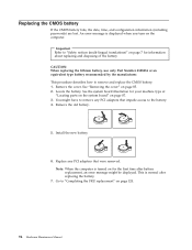
...cover. This is displayed when you turn on page 120. 94 Hardware Maintenance Manual Go to remove and replace the CMOS battery. 1. Install the new battery. 6. This procedure describes how to "Completing the FRU replacement" on the computer. See the system board illustration for ... "Locating parts on the system board" on page 85. 2. Locate the battery. Replacing the CMOS battery If the CMOS battery fails, the date, time, and configuration information (including passwords) are lost. Important Refer to the battery. 4. See "Removing the cover" on page 87. 3. Note: When...
...cover. This is displayed when you turn on page 120. 94 Hardware Maintenance Manual Go to remove and replace the CMOS battery. 1. Install the new battery. 6. This procedure describes how to "Completing the FRU replacement" on the computer. See the system board illustration for ... "Locating parts on the system board" on page 85. 2. Locate the battery. Replacing the CMOS battery If the CMOS battery fails, the date, time, and configuration information (including passwords) are lost. Important Refer to the battery. 4. See "Removing the cover" on page 87. 3. Note: When...

Hardware Maintenance Manual
Page 131
Machine types 7816, 7817, 9686 and 9687 1 Microprocessor fan connector 14 Front USB connectors (2) 2 Microprocessor and heat sink 15 Battery 3 Memory connector 1 16 Clear CMOS/Recovery jumper 4 Memory connector 2 17 Serial (COM) connector 5 Memory connector 3 18 PCI adapter connectors 6 Memory connector 4 19 Mono (speaker) connector 7 ...
Machine types 7816, 7817, 9686 and 9687 1 Microprocessor fan connector 14 Front USB connectors (2) 2 Microprocessor and heat sink 15 Battery 3 Memory connector 1 16 Clear CMOS/Recovery jumper 4 Memory connector 2 17 Serial (COM) connector 5 Memory connector 3 18 PCI adapter connectors 6 Memory connector 4 19 Mono (speaker) connector 7 ...

Hardware Maintenance Manual
Page 132
... fan connector 14 Front USB connectors (2) 15 Serial (COM) connector 16 Front audio connector 17 PCI adapter connector 18 PCI Express x1 adapter connectors (2) 19 Battery 20 PCI Express x16 graphics adapter connector 21 System fan connector 22 12 V power connector 126 Hardware Maintenance Manual
... fan connector 14 Front USB connectors (2) 15 Serial (COM) connector 16 Front audio connector 17 PCI adapter connector 18 PCI Express x1 adapter connectors (2) 19 Battery 20 PCI Express x16 graphics adapter connector 21 System fan connector 22 12 V power connector 126 Hardware Maintenance Manual
Hardware Maintenance Manual
Page 133
... connector 16 Front audio connector 6 Diskette drive connector 17 PCI adapter connectors (2) 7 IDE connector 18 PCI Express x1 adapter connector 8 Clear CMOS/Recovery jumpers 19 Battery (2) 9 Power fan connector 20 PCI Express x16 graphics adapter connector 10 SATA IDE connectors (4) 21 System fan connector 11 Front panel connector 22 12 V power...
... connector 16 Front audio connector 6 Diskette drive connector 17 PCI adapter connectors (2) 7 IDE connector 18 PCI Express x1 adapter connector 8 Clear CMOS/Recovery jumpers 19 Battery (2) 9 Power fan connector 20 PCI Express x16 graphics adapter connector 10 SATA IDE connectors (4) 21 System fan connector 11 Front panel connector 22 12 V power...
Hardware Maintenance Manual
Page 166
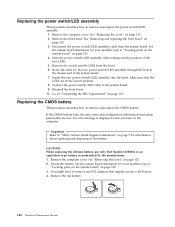
... parts on the system board" on page 161. Go to "Safety notices (multi-lingual translations)" on page 125. 3. If the CMOS battery fails, the date, time, and configuration information (including passwords) are in the chassis and to remove any PCI adapters that the LEDs are...123. 2. Note the power switch/LED assembly cable routing and the position of the battery. Remove the computer cover. CAUTION: When replacing the lithium battery, use only Part Number 33F8354 or an equivalent type battery recommended by the manufacturer. 1. See "Removing the cover" on page 123. 2. ...
... parts on the system board" on page 161. Go to "Safety notices (multi-lingual translations)" on page 125. 3. If the CMOS battery fails, the date, time, and configuration information (including passwords) are in the chassis and to remove any PCI adapters that the LEDs are...123. 2. Note the power switch/LED assembly cable routing and the position of the battery. Remove the computer cover. CAUTION: When replacing the lithium battery, use only Part Number 33F8354 or an equivalent type battery recommended by the manufacturer. 1. See "Removing the cover" on page 123. 2. ...
Hardware Maintenance Manual
Page 167
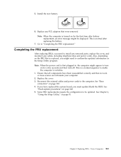
Go to the computer. Reconnect the external cables and power cords to "Completing the FRU replacement." Install the new battery. 6. Replace any cables, including telephone lines and power cords. Also, depending on for a few seconds and then turn off. Ensure that were removed. Replacing... 6, "Using the Setup Utility," on page 122. 4. Note: When the computer is first plugged in the Setup Utility program. This is normal after battery replacement, an error message might appear to initialize. 1. See "Flash update procedures" on for the first time after replacing the...
Go to the computer. Reconnect the external cables and power cords to "Completing the FRU replacement." Install the new battery. 6. Replace any cables, including telephone lines and power cords. Also, depending on for a few seconds and then turn off. Ensure that were removed. Replacing... 6, "Using the Setup Utility," on page 122. 4. Note: When the computer is first plugged in the Setup Utility program. This is normal after battery replacement, an error message might appear to initialize. 1. See "Flash update procedures" on for the first time after replacing the...
Hardware Maintenance Manual
Page 170
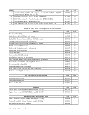
...(AMD AM2 Sempron, Athlon64,Athlon64x2 ;Gb LAN) PCB 2.0 SDV-SIT Level (models 32B 32H 23S ) 10 220 Watt Power Supply - China, Thailand (models 32B 32H) BATTERY 3V-LITHIUM (all models) FRU# 41R4808 41A7182 43N9012 41R6211 41R6226 41R6273 41R6227 41R6425 41R6228 41R6210 41R6213 41R6229 41N8217 41R2507 41R6231 41R6234 41R6235 CRU 2 N 2 N N N N N N N N N N N N N N 9680 Keyboards...
...(AMD AM2 Sempron, Athlon64,Athlon64x2 ;Gb LAN) PCB 2.0 SDV-SIT Level (models 32B 32H 23S ) 10 220 Watt Power Supply - China, Thailand (models 32B 32H) BATTERY 3V-LITHIUM (all models) FRU# 41R4808 41A7182 43N9012 41R6211 41R6226 41R6273 41R6227 41R6425 41R6228 41R6210 41R6213 41R6229 41N8217 41R2507 41R6231 41R6234 41R6235 CRU 2 N 2 N N N N N N N N N N N N N N 9680 Keyboards...
Hardware Maintenance Manual
Page 177
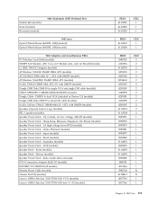
...) Speaker Power brick - India, South Africa (models) DVI-I Connection Adapter (full)/LP (models) BATTERY 3V-LITHIUM (all models) Modem Phone Cable (models) Chassis Fit (DT) (models) Lenovo USB2.0 Safe key TGE YT300 1GB V1.51 (models) Lenovo USB2.0 Safe key TGE YT300 1GB new V 1.52 (models) FRU# 41A5325 41A5323 41A5329 CRU ...with DMS59 (models) ATI Radeon X1600PRO 256MB 128bit ATX (models) Nvidia 7300LE 128MB 64bit ATX/LP with DMS59 (models) Speakers (2-piece) Lenovo Logo (models) BTL 1 speaker (models) Speaker Power brick - US, Canada, LA low voltage, ASEAN (models) Speaker Power brick -
...) Speaker Power brick - India, South Africa (models) DVI-I Connection Adapter (full)/LP (models) BATTERY 3V-LITHIUM (all models) Modem Phone Cable (models) Chassis Fit (DT) (models) Lenovo USB2.0 Safe key TGE YT300 1GB V1.51 (models) Lenovo USB2.0 Safe key TGE YT300 1GB new V 1.52 (models) FRU# 41A5325 41A5323 41A5329 CRU ...with DMS59 (models) ATI Radeon X1600PRO 256MB 128bit ATX (models) Nvidia 7300LE 128MB 64bit ATX/LP with DMS59 (models) Speakers (2-piece) Lenovo Logo (models) BTL 1 speaker (models) Speaker Power brick - US, Canada, LA low voltage, ASEAN (models) Speaker Power brick -
Hardware Maintenance Manual
Page 188
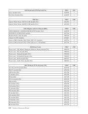
..., USB) models 23G ) 9683 Adapters and miscellaneous FRUs USB2.0 MEMORY CARDREADER,6X2,ROHS (models 23G) BATTERY 3V-LITHIUM (all models) Modem Phone Cable (models) Chassis Fit (DT) (models) Lenovo USB2.0 Safe key TGE YT300 1GB V1.51 (models) Lenovo USB2.0 Safe key TGE YT300 1GB new V 1.52 (models) 9683 Power Cords Power cord -
..., USB) models 23G ) 9683 Adapters and miscellaneous FRUs USB2.0 MEMORY CARDREADER,6X2,ROHS (models 23G) BATTERY 3V-LITHIUM (all models) Modem Phone Cable (models) Chassis Fit (DT) (models) Lenovo USB2.0 Safe key TGE YT300 1GB V1.51 (models) Lenovo USB2.0 Safe key TGE YT300 1GB new V 1.52 (models) 9683 Power Cords Power cord -
Hardware Maintenance Manual
Page 195
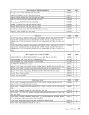
... 42B 42H 63B 63H 23S ) USB2.0 Safe key TGE YT300 1GB V1.51 (models 6CG 5CG) USB2.0 Safe key TGE YT300 1GB new V 1.52 (models) BATTERY 3V-LITHIUM (all models) Speaker Power brick - G models (Denmark, South Africa, UK, Ireland, Singapore, Malaysia, Brunei, Switzerland, Italy, and Israel) (models 6BG 6CG 6DG) Power...
... 42B 42H 63B 63H 23S ) USB2.0 Safe key TGE YT300 1GB V1.51 (models 6CG 5CG) USB2.0 Safe key TGE YT300 1GB new V 1.52 (models) BATTERY 3V-LITHIUM (all models) Speaker Power brick - G models (Denmark, South Africa, UK, Ireland, Singapore, Malaysia, Brunei, Switzerland, Italy, and Israel) (models 6BG 6CG 6DG) Power...


