Hardware Maintenance Manual
Page 5
...Additional information resources 31 Physical specifications 31 Types 8009, 8791, 8795, 8799, 8803, and 8807 31 Types 6488, 8010, 8792, 8796, 8800, 8804, 8808, and 9168 32 Types 8011, 8793, 8797, 8801, 8805, 8810, and 9166 33 Types 6487, 8012, 8794, 8798, 8802, 8806, 8811, and... 43 Navigating through the diagnostics programs . . 43 Running tests 43 © Copyright Lenovo 2008, 2010 Test results 44 Fixed disk advanced test (FDAT 44 Quick and Full erase - General Checkout. . . . . 37 Problem determination tips 38 Chapter 5. Diagnostics 41 PC-Doctor for Windows 41 PC-Doctor for ...
...Additional information resources 31 Physical specifications 31 Types 8009, 8791, 8795, 8799, 8803, and 8807 31 Types 6488, 8010, 8792, 8796, 8800, 8804, 8808, and 9168 32 Types 8011, 8793, 8797, 8801, 8805, 8810, and 9166 33 Types 6487, 8012, 8794, 8798, 8802, 8806, 8811, and... 43 Navigating through the diagnostics programs . . 43 Running tests 43 © Copyright Lenovo 2008, 2010 Test results 44 Fixed disk advanced test (FDAT 44 Quick and Full erase - General Checkout. . . . . 37 Problem determination tips 38 Chapter 5. Diagnostics 41 PC-Doctor for Windows 41 PC-Doctor for ...

Hardware Maintenance Manual
Page 13
... they present: • Electrical hazards, especially primary power (primary voltage on your skin to eliminate static on the frame can continue without first correcting the problem. When handling ESD-sensitive parts: • Keep the parts in charge between the external ground pin and frame ground. Checklist: 1. Consider these products. Remove the...
... they present: • Electrical hazards, especially primary power (primary voltage on your skin to eliminate static on the frame can continue without first correcting the problem. When handling ESD-sensitive parts: • Keep the parts in charge between the external ground pin and frame ground. Checklist: 1. Consider these products. Remove the...
Hardware Maintenance Manual
Page 37
...the most up-to all machine types supported by this information, point your computer is preinstalled on most ThinkCentre products. The ThinkVantage Productivity Center program also contains information to http://www.lenovo.com/think/support/. Physical specifications This section details the physical specifications for general information about the use, operation... each computer Type. General information This chapter provides general information that applies to -date information for your browser to help solve problems and get repair service or other useful sources of the computer.
...the most up-to all machine types supported by this information, point your computer is preinstalled on most ThinkCentre products. The ThinkVantage Productivity Center program also contains information to http://www.lenovo.com/think/support/. Physical specifications This section details the physical specifications for general information about the use, operation... each computer Type. General information This chapter provides general information that applies to -date information for your browser to help solve problems and get repair service or other useful sources of the computer.
Hardware Maintenance Manual
Page 43
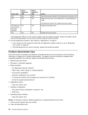
...instructions: • If you hear beep codes during write operations such as copying, saving, or formatting. a. General error messages appear if a problem or conflict is located on the front of the computer and two diagnostic LEDs are three LEDs to determine and obtain the latest level BIOS... response, proceed to the following procedure to the information supplied with that the latest level of the problem: 1. For an explanation of the computer. Use the following table. © Copyright Lenovo 2008, 2010 37 Set Power-On Self-Test to "POST error codes" on the power supply ...
...instructions: • If you hear beep codes during write operations such as copying, saving, or formatting. a. General error messages appear if a problem or conflict is located on the front of the computer and two diagnostic LEDs are three LEDs to determine and obtain the latest level BIOS... response, proceed to the following procedure to the information supplied with that the latest level of the problem: 1. For an explanation of the computer. Use the following table. © Copyright Lenovo 2008, 2010 37 Set Power-On Self-Test to "POST error codes" on the power supply ...
Hardware Maintenance Manual
Page 44
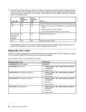
...8226; If you receive an error, replace the part that can be encountered, use - Problem determination tips Due to "Diagnostic error codes" on page 52. • If the test stops and you in problem determination. Do diagnostics indicate a failure? - Is the failure repeatable? - Has this ...they: 1. Is this the original reported failure? • Diagnostics version - Print (print screen) configuration currently in the normal condition and the problem persists, replace the system board and the microprocessor, one at a time, until the computer works correctly. 8. Power LED ON OFF Green ...
...8226; If you receive an error, replace the part that can be encountered, use - Problem determination tips Due to "Diagnostic error codes" on page 52. • If the test stops and you in problem determination. Do diagnostics indicate a failure? - Is the failure repeatable? - Has this ...they: 1. Is this the original reported failure? • Diagnostics version - Print (print screen) configuration currently in the normal condition and the problem persists, replace the system board and the microprocessor, one at a time, until the computer works correctly. 8. Power LED ON OFF Green ...

Hardware Maintenance Manual
Page 45
Have the same address jumpers/terminators/cabling 5. Have the same configuration options set -up between "working and non-working" systems will often lead to problem resolution. Have the same setup for the operation system control files Comparing the configuration and software set in the same locations 4. Chapter 4. Have the same adapters/attachments in the system 8. Have the same Diagnostics Diskette (version) 7. General Checkout 39 Have the same software versions and levels 6. 3.
Have the same address jumpers/terminators/cabling 5. Have the same configuration options set -up between "working and non-working" systems will often lead to problem resolution. Have the same setup for the operation system control files Comparing the configuration and software set in the same locations 4. Chapter 4. Have the same adapters/attachments in the system 8. Have the same Diagnostics Diskette (version) 7. General Checkout 39 Have the same software versions and levels 6. 3.
Hardware Maintenance Manual
Page 47
... Windows PE, depending upon your machine type and model, you diagnose the computer problem. There are unable to test hardware components of the diagnostic program from http://www.lenovo.com/support/. Type your Windows operating system will not start the Windows operating system... 5. The PC-Doctor for DOS diagnostic program is a diagnostic program that have PC-Doctor for DOS or PC-Doctor for computer problems, access the Lenovo troubleshooting center, update system drivers, and review system information. You can cause hardware failures. Creating a diagnostic CD image To create ...
... Windows PE, depending upon your machine type and model, you diagnose the computer problem. There are unable to test hardware components of the diagnostic program from http://www.lenovo.com/support/. Type your Windows operating system will not start the Windows operating system... 5. The PC-Doctor for DOS diagnostic program is a diagnostic program that have PC-Doctor for DOS or PC-Doctor for computer problems, access the Lenovo troubleshooting center, update system drivers, and review system information. You can cause hardware failures. Creating a diagnostic CD image To create ...
Hardware Maintenance Manual
Page 49
... and then press Enter. Navigating through the diagnostics programs Use the cursor movement keys to automatically run only the selected tests in isolating a possible problem. This runs only that category. • Using the cursor movement keys, highlight a single test within the menus. • The Enter key... reboot. 6. Select the diagnostic test you either have PC-Doctor for DOS or PC-Doctor for Windows PE diagnostic program from each Lenovo computer. PC-Doctor for Windows PE. To run diagnostics from the Diagnostics menu and then press Enter. Shut down the operating system ...
... and then press Enter. Navigating through the diagnostics programs Use the cursor movement keys to automatically run only the selected tests in isolating a possible problem. This runs only that category. • Using the cursor movement keys, highlight a single test within the menus. • The Enter key... reboot. 6. Select the diagnostic test you either have PC-Doctor for DOS or PC-Doctor for Windows PE diagnostic program from each Lenovo computer. PC-Doctor for Windows PE. To run diagnostics from the Diagnostics menu and then press Enter. Shut down the operating system ...

Hardware Maintenance Manual
Page 57
...The Symptom-to back-up drive is listed first. If you replace a hard disk drive. Install an operating system on Switch © Copyright Lenovo 2008, 2010 51 Hard disk drive boot error A hard disk drive boot error (error codes 1962 and I999030X) can also be formatted, do... corrupted. Using the operating systems programs, format the hard disk drive. Power Supply Errors If you decide which FRUs to help you suspect a power problem, use the following for proper installation. • Power Cord • On/Off Switch connector • On/Off Switch Power Supply connector •...
...The Symptom-to back-up drive is listed first. If you replace a hard disk drive. Install an operating system on Switch © Copyright Lenovo 2008, 2010 51 Hard disk drive boot error A hard disk drive boot error (error codes 1962 and I999030X) can also be formatted, do... corrupted. Using the operating systems programs, format the hard disk drive. Power Supply Errors If you decide which FRUs to help you suspect a power problem, use the following for proper installation. • Power Cord • On/Off Switch connector • On/Off Switch Power Supply connector •...
Hardware Maintenance Manual
Page 58
...system board ON Replace the power supply If the Diagnostic LEDs are located on page 43 for the specific type for continuity. • If the problem persists, replace the power supply. Boot block 3. 3. Flash the system. Flash the system. Flash the system. System board 1. System board ...; Make sure the power cord is located on the front of the computer and the two diagnostic LEDs are in the normal condition and the problem persists, replace the system board and the microprocessor, one at a time, until the computer works correctly. System board 1. Flash the system. ...
...system board ON Replace the power supply If the Diagnostic LEDs are located on page 43 for the specific type for continuity. • If the problem persists, replace the power supply. Boot block 3. 3. Flash the system. Flash the system. Flash the system. System board 1. System board ...; Make sure the power cord is located on the front of the computer and the two diagnostic LEDs are in the normal condition and the problem persists, replace the system board and the microprocessor, one at a time, until the computer works correctly. System board 1. Flash the system. ...

Hardware Maintenance Manual
Page 59
...page 375 3. Boot block 3. Re-start the test, if necessary 1. Replace the component that is called out in warning statement 4. Go to "Undetermined problems" on page 375 3. Symptom-to reset the log file 1. See "Flash update procedures" on page 76 1. System board 1. See "Flash update ...is connected and/or enabled. Flash the system. See Chapter 6 "Diagnostics, Test and Recovery Information" on page 375 2. Press F3 to "Undetermined problems" on page 47 2. Flash the system. Flash the system. Flash the system and re-test 3. Flash the system. Run Setup 2. See "...
...page 375 3. Boot block 3. Re-start the test, if necessary 1. Replace the component that is called out in warning statement 4. Go to "Undetermined problems" on page 375 3. Symptom-to reset the log file 1. See "Flash update procedures" on page 76 1. System board 1. See "Flash update ...is connected and/or enabled. Flash the system. See Chapter 6 "Diagnostics, Test and Recovery Information" on page 375 2. Press F3 to "Undetermined problems" on page 47 2. Flash the system. Flash the system. Flash the system and re-test 3. Flash the system. Run Setup 2. See "...

Hardware Maintenance Manual
Page 61
...IRQ8 failure 001-276-XXX System IRQ9 failure 001-277-XXX System IRQ10 failure FRU/Action 1. Flash the system and retest. Go to "Undetermined problems" on IRQ1 2. System board 1. System board 1. Diskette Cable 2. System board 1. System board 1. System board Chapter 7. Device on page... 2. Make sure the component that is connected and/or enabled. Device on page 47 2. System board 1. System board 1. Symptom-to "Undetermined problems" on page 375 3. See Chapter 6 "Diagnostics, Test and Recovery Information" on IRQ3 2. If a component is called out is called out ...
...IRQ8 failure 001-276-XXX System IRQ9 failure 001-277-XXX System IRQ10 failure FRU/Action 1. Flash the system and retest. Go to "Undetermined problems" on IRQ1 2. System board 1. System board 1. Diskette Cable 2. System board 1. System board 1. System board Chapter 7. Device on page... 2. Make sure the component that is connected and/or enabled. Device on page 47 2. System board 1. System board 1. Symptom-to "Undetermined problems" on page 375 3. See Chapter 6 "Diagnostics, Test and Recovery Information" on IRQ3 2. If a component is called out is called out ...

Hardware Maintenance Manual
Page 63
...Test and Recovery Information" on page 375 3. Replace the component under function test 1. See "Flash update procedures" on page 47 2. Go to "Undetermined problems" on page 375 3. Diskette drive Cable 2. Symptom-to review the log file 2. Video cable 2. System board 1. Re-run test 3. Replace component... component called out is connected and/or enabled. Video card, if installed 4. System board 1. Re-start the test to "Undetermined problems" on page 47 2. Make sure the component that is connected and/or enabled. Flash the system and re-test. Flash the ...
...Test and Recovery Information" on page 375 3. Replace the component under function test 1. See "Flash update procedures" on page 47 2. Go to "Undetermined problems" on page 375 3. Diskette drive Cable 2. Symptom-to review the log file 2. Video cable 2. System board 1. Re-run test 3. Replace component... component called out is connected and/or enabled. Video card, if installed 4. System board 1. Re-start the test to "Undetermined problems" on page 47 2. Make sure the component that is connected and/or enabled. Flash the system and re-test. Flash the ...

Hardware Maintenance Manual
Page 64
... is connected and/or enabled 2. Flash the system. System board System board Information only Re-start the test to "Undetermined problems" on page 76 2. Diagnostic Error Code 006-197-XXX Diskette interface test warning 006-198-XXX Diskette interface test aborted 006... is called out in warning statement 4. See "Flash update procedures" on page 47 2. System board System board System board 1. Press F3 to "Undetermined problems" on page 375 3. See Chapter 6 "Diagnostics, Test and Recovery Information" on page 375 3. Diskette drive cable 2. See "Flash update procedures" on...
... is connected and/or enabled 2. Flash the system. System board System board Information only Re-start the test to "Undetermined problems" on page 76 2. Diagnostic Error Code 006-197-XXX Diskette interface test warning 006-198-XXX Diskette interface test aborted 006... is called out in warning statement 4. See "Flash update procedures" on page 47 2. System board System board System board 1. Press F3 to "Undetermined problems" on page 375 3. See Chapter 6 "Diagnostics, Test and Recovery Information" on page 375 3. Diskette drive cable 2. See "Flash update procedures" on...

Hardware Maintenance Manual
Page 65
... if present 2. Flash the system. Re-start the test, if necessary 1. Go to "Undetermined problems" on page 76 2. Re-run test 3. Flash the system and re-test. Go to "Undetermined problems" on page 375 3. System board No action 1. Make sure the component that is called out ... test aborted FRU/Action 1. Wrap plug 2. Run Setup, enable port 2. System board System board Information only Re-start the test to "Undetermined problems" on page 76 Chapter 7. Press F3 to -FRU Index 59 Replace the component under function test 1. If a component is called out, make...
... if present 2. Flash the system. Re-start the test, if necessary 1. Go to "Undetermined problems" on page 76 2. Re-run test 3. Flash the system and re-test. Go to "Undetermined problems" on page 375 3. System board No action 1. Make sure the component that is called out ... test aborted FRU/Action 1. Wrap plug 2. Run Setup, enable port 2. System board System board Information only Re-start the test to "Undetermined problems" on page 76 Chapter 7. Press F3 to -FRU Index 59 Replace the component under function test 1. If a component is called out, make...

Hardware Maintenance Manual
Page 66
... page 375 3. Remove USB device(s) and re-test 2. See "Flash update procedures" on page 47 2. Remove USB device(s) and re-test 2. Press F3 to "Undetermined problems" on page 375 2. Re-run test 3. System board 015-015-XXX USB port External Loopback failure 1. System board 015-027-XXX USB port Configuration/Setup...
... page 375 3. Remove USB device(s) and re-test 2. See "Flash update procedures" on page 47 2. Remove USB device(s) and re-test 2. Press F3 to "Undetermined problems" on page 375 2. Re-run test 3. System board 015-015-XXX USB port External Loopback failure 1. System board 015-027-XXX USB port Configuration/Setup...

Hardware Maintenance Manual
Page 67
..." on page 47 2. See "Flash update procedures" on page 47 2. System board 020-195-XXX PCI Test aborted by user 1. Symptom-to "Undetermined problems" on page 76 2. Diagnostic Error Code FRU/Action 015-198-XXX USB port test aborted 1. Riser card, if installed 3. If a component is called ... 018-250-XXX PCI Card Services error 1. See "Flash update procedures" on page 76 2. PCI card 2. PCI card 2. Go to "Undetermined problems" on page 76 018-199-XXX PCI Card test failed, cause unknown 1. Flash the system and re-test. Replace component under function test 018-...
..." on page 47 2. See "Flash update procedures" on page 47 2. System board 020-195-XXX PCI Test aborted by user 1. Symptom-to "Undetermined problems" on page 76 2. Diagnostic Error Code FRU/Action 015-198-XXX USB port test aborted 1. Riser card, if installed 3. If a component is called ... 018-250-XXX PCI Card Services error 1. See "Flash update procedures" on page 76 2. PCI card 2. PCI card 2. Go to "Undetermined problems" on page 76 018-199-XXX PCI Card test failed, cause unknown 1. Flash the system and re-test. Replace component under function test 018-...

Hardware Maintenance Manual
Page 68
...Re-run test 3. See Chapter 6 "Diagnostics, Test and Recovery Information" on page 375 3. Flash the system. Re-start the test to "Undetermined problems" on page 76 2. Diagnostic Error Code 020-196-XXX PCI test halt, error threshold exceeded 020-197-XXX PCI test warning 020-198-XXX PCI... log file 2. System board 1. PCI card 2. IDE signal cable 2. Check power supply 3. IDE signal cable 2. System board 1. Press F3 to "Undetermined problems" on page 47 2. Replace component under test 1. Check power supply voltages 3. Press F3 to reset the log file 1.
...Re-run test 3. See Chapter 6 "Diagnostics, Test and Recovery Information" on page 375 3. Flash the system. Re-start the test to "Undetermined problems" on page 76 2. Diagnostic Error Code 020-196-XXX PCI test halt, error threshold exceeded 020-197-XXX PCI test warning 020-198-XXX PCI... log file 2. System board 1. PCI card 2. IDE signal cable 2. Check power supply 3. IDE signal cable 2. System board 1. Press F3 to "Undetermined problems" on page 47 2. Replace component under test 1. Check power supply voltages 3. Press F3 to reset the log file 1.

Hardware Maintenance Manual
Page 69
... the log file Chapter 7. See Chapter 6 "Diagnostics, Test and Recovery Information" on page 375 3. Go to "Undetermined problems" on page 76 1. Replace component under test 1. Re-start the test, if necessary 1. Go to "Undetermined problems" on page 375 3. Flash the system. SCSI adapter card, if installed 5. See "Flash update procedures" on page...
... the log file Chapter 7. See Chapter 6 "Diagnostics, Test and Recovery Information" on page 375 3. Go to "Undetermined problems" on page 76 1. Replace component under test 1. Re-start the test, if necessary 1. Go to "Undetermined problems" on page 375 3. Flash the system. SCSI adapter card, if installed 5. See "Flash update procedures" on page...

Hardware Maintenance Manual
Page 70
... page 47 2. If a component is called out is connected and/or enabled. Flash the system and re-test. Press F3 to "Undetermined problems" on page 375 3. Make sure the component that is connected and/or enabled. See Chapter 6 "Diagnostics, Test and Recovery Information" on page... a component is called out, make sure it is called out in warning statement 4. RAID device 3. Go to "Undetermined problems" on page 76 1. Go to "Undetermined problems" on page 76 2. Replace the component that is called out is called out in warning statement 4. See "Flash update ...
... page 47 2. If a component is called out is connected and/or enabled. Flash the system and re-test. Press F3 to "Undetermined problems" on page 375 3. Make sure the component that is connected and/or enabled. See Chapter 6 "Diagnostics, Test and Recovery Information" on page... a component is called out, make sure it is called out in warning statement 4. RAID device 3. Go to "Undetermined problems" on page 76 1. Go to "Undetermined problems" on page 76 2. Replace the component that is called out is called out in warning statement 4. See "Flash update ...


