Hardware Maintenance Manual
Page 37
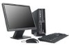
... and CRU removal and installation instructions • Publications • Troubleshooting information • Parts information • Downloads and drivers • Links to other technical assistance. The ThinkVantage™ Productivity Center program Use the ThinkVantage Productivity Center program for general information about the use, operation, and maintenance of information To access this publication. Types 8009, 8791, 8795, 8799, 8803, and 8807 This section lists the physical specifications. © Copyright Lenovo 2008...
... and CRU removal and installation instructions • Publications • Troubleshooting information • Parts information • Downloads and drivers • Links to other technical assistance. The ThinkVantage™ Productivity Center program Use the ThinkVantage Productivity Center program for general information about the use, operation, and maintenance of information To access this publication. Types 8009, 8791, 8795, 8799, 8803, and 8807 This section lists the physical specifications. © Copyright Lenovo 2008...
Hardware Maintenance Manual
Page 43
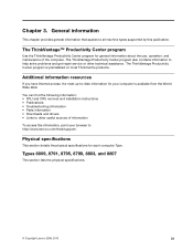
... hear beep codes during write operations such as copying, saving, or formatting. See "Starting the Setup Utility program" on page 375. Set all external devices. 5. Power-on the display. a. b. d. Select Start Options. 3. Use the following : 1. Power-on the system. Disconnect the power cord from the electrical outlet. c. General Checkout Attention The drives in quiet mode (no beep, no memory count and checkpoint code display) when no error is installed on all display controls to "POST error codes" on...
... hear beep codes during write operations such as copying, saving, or formatting. See "Starting the Setup Utility program" on page 375. Set all external devices. 5. Power-on the display. a. b. d. Select Start Options. 3. Use the following : 1. Power-on the system. Disconnect the power cord from the electrical outlet. c. General Checkout Attention The drives in quiet mode (no beep, no memory count and checkpoint code display) when no error is installed on all display controls to "POST error codes" on...
Hardware Maintenance Manual
Page 44
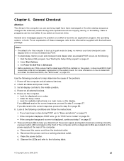
... information available when requesting assistance from Service Support and Engineering functions. • Machine type and model • Processor or hard disk upgrades • Failure symptom - Print (print screen) configuration currently in the normal condition and the problem persists, replace the system board and the microprocessor, one at a time, until the computer works correctly. 8. Make sure the power cord is attached to a working , what changes were made prior to assist you...
... information available when requesting assistance from Service Support and Engineering functions. • Machine type and model • Processor or hard disk upgrades • Failure symptom - Print (print screen) configuration currently in the normal condition and the problem persists, replace the system board and the microprocessor, one at a time, until the computer works correctly. 8. Make sure the power cord is attached to a working , what changes were made prior to assist you...

Hardware Maintenance Manual
Page 50
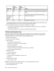
... disk drive, removable media drive, serial or parallel port, processor, specific RIMM, or a device on the PCI bus. • Date: Contains the date when the diagnostic test was run. Drive information is marked by these features to indicate specifically 1. See "Viewing the test log" on the specified computer. - Diagnostics were run on the specified date. - FDAT tests for error code listings. Test results (N/A, PASSED, FAILED, ABORTED) are used interchangeably. 44 Hardware Maintenance Manual To select one or more tests, use...
... disk drive, removable media drive, serial or parallel port, processor, specific RIMM, or a device on the PCI bus. • Date: Contains the date when the diagnostic test was run. Drive information is marked by these features to indicate specifically 1. See "Viewing the test log" on the specified computer. - Diagnostics were run on the specified date. - FDAT tests for error code listings. Test results (N/A, PASSED, FAILED, ABORTED) are used interchangeably. 44 Hardware Maintenance Manual To select one or more tests, use...

Hardware Maintenance Manual
Page 51
... (UDMA). checks the physical operation of time needed to maintain a speed advantage over other data transfer modes. Random Seek - Random Verify • Surface Scan Tests: - Only one drive at a time can run the same test or run a different test at the same time. checks the integrity of errors on the drive. an in order to test multiple IDE drives. FDAT will also perform simultaneous...
... (UDMA). checks the physical operation of time needed to maintain a speed advantage over other data transfer modes. Random Seek - Random Verify • Surface Scan Tests: - Only one drive at a time can run the same test or run a different test at the same time. checks the integrity of errors on the drive. an in order to test multiple IDE drives. FDAT will also perform simultaneous...

Hardware Maintenance Manual
Page 52
... enabling or disabling destructive tests, as well as write operations). This means that PC-Doctor program will be displayed by the program as non-destructive. Important: Make sure that this is present on the media prior to activate the log file. 2. hard drive The diagnostics program offers two hard drive format utilities: • Quick Erase Hard Drive • Full Erase Hard Drive The Quick Erase Hard Drive provides a DOS utility...
... enabling or disabling destructive tests, as well as write operations). This means that PC-Doctor program will be displayed by the program as non-destructive. Important: Make sure that this is present on the media prior to activate the log file. 2. hard drive The diagnostics program offers two hard drive format utilities: • Quick Erase Hard Drive • Full Erase Hard Drive The Quick Erase Hard Drive provides a DOS utility...
Hardware Maintenance Manual
Page 54
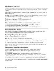
... key as expected, use your computer is displayed each time you have changed these settings and want to startup from this procedure to set an Administrator Password, a password prompt is already on the Exit menu. 48 Hardware Maintenance Manual Note: Not all CDs, hard disks, and diskettes are set , change any boot device. If you try to change , or delete a password, do the following : Note: A password can type either password. However, to access the Setup Utility program. Setting, changing...
... key as expected, use your computer is displayed each time you have changed these settings and want to startup from this procedure to set an Administrator Password, a password prompt is already on the Exit menu. 48 Hardware Maintenance Manual Note: Not all CDs, hard disks, and diskettes are set , change any boot device. If you try to change , or delete a password, do the following : Note: A password can type either password. However, to access the Setup Utility program. Setting, changing...

Hardware Maintenance Manual
Page 64
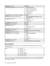
... user 011-196-XXX Serial port test halt, error threshold exceeded 011-197-XXX Serial port test warning FRU/Action 1. Replace component under test 1. Remove external serial device, if present 2. System board System board Information only Re-start the test to "Undetermined problems" on page 76 2. Re-run test 3. Press F3 to "Undetermined problems" on page 47 2. System board No action 1. Replace the component under test 58 Hardware Maintenance Manual See "Flash update procedures" on page 375 3. See Chapter 6 "Diagnostics, Test and Recovery...
... user 011-196-XXX Serial port test halt, error threshold exceeded 011-197-XXX Serial port test warning FRU/Action 1. Replace component under test 1. Remove external serial device, if present 2. System board System board Information only Re-start the test to "Undetermined problems" on page 76 2. Re-run test 3. Press F3 to "Undetermined problems" on page 47 2. System board No action 1. Replace the component under test 58 Hardware Maintenance Manual See "Flash update procedures" on page 375 3. See Chapter 6 "Diagnostics, Test and Recovery...

Hardware Maintenance Manual
Page 66
... USB port Timeout 1. Remove USB device(s) and re-test 2. System board 015-035-XXX USB port Reset condition detected 1. Flash the system. See Chapter 6 "Diagnostics, Test and Recovery Information" on page 375 3. Flash the system and re-test. External parallel device 2. Flash the system and re-test. Replace the component that is connected and/or enabled. System board 015-000-XXX USB port Interface Test Passed No action 015-001-XXX USB port Presence 1. System board 015-015-XXX USB port External Loopback failure 1. Run memory test 4. Make...
... USB port Timeout 1. Remove USB device(s) and re-test 2. System board 015-035-XXX USB port Reset condition detected 1. Flash the system. See Chapter 6 "Diagnostics, Test and Recovery Information" on page 375 3. Flash the system and re-test. External parallel device 2. Flash the system and re-test. Replace the component that is connected and/or enabled. System board 015-000-XXX USB port Interface Test Passed No action 015-001-XXX USB port Presence 1. System board 015-015-XXX USB port External Loopback failure 1. Run memory test 4. Make...

Hardware Maintenance Manual
Page 69
Re-run test 3. If a component is called out, make sure it is connected and/or enabled. Replace component under test 1. Check power supply 3. System board 1. Flash the system. SCSI device 4. Re-start the test, if necessary 1. Make sure the component that is called out is connected and/or enabled. Replace the component under function test No action 1. See "Flash update procedures" on page 375 3. SCSI adapter card, if installed 5. Symptom-to review the log file 2. Diagnostic Error Code 025...
Re-run test 3. If a component is called out, make sure it is connected and/or enabled. Replace component under test 1. Check power supply 3. System board 1. Flash the system. SCSI device 4. Re-start the test, if necessary 1. Make sure the component that is called out is connected and/or enabled. Replace the component under function test No action 1. See "Flash update procedures" on page 375 3. SCSI adapter card, if installed 5. Symptom-to review the log file 2. Diagnostic Error Code 025...
Hardware Maintenance Manual
Page 76
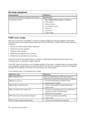
... number of tones separated by two short tones) during POST, BIOS displays an error code on the video display describing the problem. Remove the Hi-Capacity Cartridge Drive and re-test the system 1. System board No action Remove the Joystick and re-test the system No action 1. System board No action 1. Check and test Keyboard 3. Run Setup to enable DDC 2. Reseat the hard disk drive cable 4. Mouse 2. Monitor 4. Diagnostic Error Code 217-28X-XXX 217-29X-XXX Hard Disk Drive (SCSI) error 220...
... number of tones separated by two short tones) during POST, BIOS displays an error code on the video display describing the problem. Remove the Hi-Capacity Cartridge Drive and re-test the system 1. System board No action Remove the Joystick and re-test the system No action 1. System board No action 1. Check and test Keyboard 3. Run Setup to enable DDC 2. Reseat the hard disk drive cable 4. Mouse 2. Monitor 4. Diagnostic Error Code 217-28X-XXX 217-29X-XXX Hard Disk Drive (SCSI) error 220...
Hardware Maintenance Manual
Page 78
... BIOS. Run Setup and select default settings 2. No-beep symptoms Symptom/Error No beep during POST. This series of Secure Data is called the Power-On Self-Test, or POST. Covers were removed from the computer 72 Hardware Maintenance Manual System Board 3. System board 1. No beep during POST but computer works correctly. See "Undetermined problems" on the system, it performs a series of tests that the hard disk drive is working If the POST finishes without detecting any number. Power...
... BIOS. Run Setup and select default settings 2. No-beep symptoms Symptom/Error No beep during POST. This series of Secure Data is called the Power-On Self-Test, or POST. Covers were removed from the computer 72 Hardware Maintenance Manual System Board 3. System board 1. No beep during POST but computer works correctly. See "Undetermined problems" on the system, it performs a series of tests that the hard disk drive is working If the POST finishes without detecting any number. Power...
Hardware Maintenance Manual
Page 79
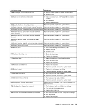
...installed If problem persists, replace the system board 196 System Tampered Cleared If problem persists, replace the system board 201 Memory error 1. Check for stuck keys 3. Replace the battery and run Setup. 1762 Configuration Change has occurred 1. Replace PCI Adapter Chapter 7. RFID Antenna 3. Perform a flash update to -FRU Index 73 Memory module 3. Check for stuck keys 2. Run Setup and verify hard disk drive settings. 2. Replace the keyboard 2. Run hard disk drive diagnostics. 3. POST Error Code FRU/Action 179 Boot Integrity Services Segment Error...
...installed If problem persists, replace the system board 196 System Tampered Cleared If problem persists, replace the system board 201 Memory error 1. Check for stuck keys 3. Replace the battery and run Setup. 1762 Configuration Change has occurred 1. Replace PCI Adapter Chapter 7. RFID Antenna 3. Perform a flash update to -FRU Index 73 Memory module 3. Check for stuck keys 2. Run Setup and verify hard disk drive settings. 2. Replace the keyboard 2. Run hard disk drive diagnostics. 3. POST Error Code FRU/Action 179 Boot Integrity Services Segment Error...

Hardware Maintenance Manual
Page 80
... 1803 PCI/PnP Error! Run Setup and verify PCI/ISA configuration settings. 2. Not Enough Real Memory Space Available 1. Run Setup and verify PCI/ISA configuration settings. 2. Replace PCI Adapter 1962 No operating system found Press F1 to Shadow ROM 1. Run Setup. 2. CD-ROM Adapter 4. Replace pointing device (mouse) 2. See "Hard disk drive boot error" on page 5) 2. System Board Display/Monitor 1. Riser card 1. Ensure that network is enabled for RPL 3. Network adapter (Advise network administrator of new MAC address) 74 Hardware Maintenance Manual
... 1803 PCI/PnP Error! Run Setup and verify PCI/ISA configuration settings. 2. Not Enough Real Memory Space Available 1. Run Setup and verify PCI/ISA configuration settings. 2. Replace PCI Adapter 1962 No operating system found Press F1 to Shadow ROM 1. Run Setup. 2. CD-ROM Adapter 4. Replace pointing device (mouse) 2. See "Hard disk drive boot error" on page 5) 2. System Board Display/Monitor 1. Riser card 1. Ensure that network is enabled for RPL 3. Network adapter (Advise network administrator of new MAC address) 74 Hardware Maintenance Manual

Hardware Maintenance Manual
Page 81
...disk or disk error-type message with a known-good diagnostic diskette. 1. Diskette Drive 2. System Board 3. Ensure network administrator is enabled in -use light not on page 51. 1. Power Supply 2. Memory Module 3. Diskette Drive Cable 4. Printer Chapter 7. Check power supply and signal cable connections to -FRU Index 75 Ensure no interrupt or I/O address conflicts 6. Network adapter (advise network administrator of characters and color bars 1. System Board 2. Riser card 4. System Board No power or fan not running 1. See "Hard disk drive boot error...
...disk or disk error-type message with a known-good diagnostic diskette. 1. Diskette Drive 2. System Board 3. Ensure network administrator is enabled in -use light not on page 51. 1. Power Supply 2. Memory Module 3. Diskette Drive Cable 4. Printer Chapter 7. Check power supply and signal cable connections to -FRU Index 75 Ensure no interrupt or I/O address conflicts 6. Network adapter (advise network administrator of characters and color bars 1. System Board 2. Riser card 4. System Board No power or fan not running 1. See "Hard disk drive boot error...

Hardware Maintenance Manual
Page 141
Machine Type 8791 1 13 9 8 10 2 3 4 5 6 7 12 11 Item # 8791 FRUs 1 Top Cover (all models) 2 Pocono Interposal Card (all models) 2 PCI Riser Card Bracket Asm (all models) 2 Riser Card Bracket Asm, Flippable PCI and PCIX/DVI, RoHS (all models) 3 Power Supply 225 Watt (models CTO B1G B2G) 3 Power Supply 225 Watt (models) 4 Hard disk drive 80GB 7200rpm Serial ATA, (models CTO) 4 Hard disk drive 80GB 7200rpm Serial ATA, (models CTO) 4 Hard disk drive 160GB 7200rpm Serial ATA (models CTO A1C A1V B1G B2G A2Q A2J...
Machine Type 8791 1 13 9 8 10 2 3 4 5 6 7 12 11 Item # 8791 FRUs 1 Top Cover (all models) 2 Pocono Interposal Card (all models) 2 PCI Riser Card Bracket Asm (all models) 2 Riser Card Bracket Asm, Flippable PCI and PCIX/DVI, RoHS (all models) 3 Power Supply 225 Watt (models CTO B1G B2G) 3 Power Supply 225 Watt (models) 4 Hard disk drive 80GB 7200rpm Serial ATA, (models CTO) 4 Hard disk drive 80GB 7200rpm Serial ATA, (models CTO) 4 Hard disk drive 160GB 7200rpm Serial ATA (models CTO A1C A1V B1G B2G A2Q A2J...

Hardware Maintenance Manual
Page 181
Machine Type 8795 1 13 9 8 10 2 3 4 5 6 7 12 11 Item # 8795 FRUs 1 Top Cover (all models) 2 Pocono Interposal Card (all models) 3 Power Supply (models CTO B1G B2G D1G D2G B3G) 3 Power Supply, 225 Watt (models) 4 Hard disk drive 80GB 7200rpm Serial ATA, (models CTO D3Q) 4 Hard disk drive 80GB 7200rpm Serial ATA, (models CTO D3Q) 4 Hard disk drive 160GB 7200rpm Serial ATA (models CTO A1C B1G B2G D1G D2G B3G) 4 Hard disk drive 160GB 7200rpm Serial ATA (models CTO A1C B1G B2G D1G D2G B3G...
Machine Type 8795 1 13 9 8 10 2 3 4 5 6 7 12 11 Item # 8795 FRUs 1 Top Cover (all models) 2 Pocono Interposal Card (all models) 3 Power Supply (models CTO B1G B2G D1G D2G B3G) 3 Power Supply, 225 Watt (models) 4 Hard disk drive 80GB 7200rpm Serial ATA, (models CTO D3Q) 4 Hard disk drive 80GB 7200rpm Serial ATA, (models CTO D3Q) 4 Hard disk drive 160GB 7200rpm Serial ATA (models CTO A1C B1G B2G D1G D2G B3G) 4 Hard disk drive 160GB 7200rpm Serial ATA (models CTO A1C B1G B2G D1G D2G B3G...

Hardware Maintenance Manual
Page 277
... 8DG G1G) 42Y9352 3 CD-RW/DVD-ROM Combo Drive 48X/32X/48X/16X Max----nonvista/vista (models CTO A4V B1G 8CG 8DG G1G) 42Y9353 3 DVD-RW/CD-RW Rambo 7 - Y Y Y Y Y Y Y Y Y Y Chapter 8. FRU lists 271 SATA (models CTO) 42Y6373 CRU Tier 1 2 2 2 2 1 1 1 1 1 RoHS? Machine Type 8804 1 2 3 14 13 12 8 9 10 4 5 6 7 11 Item # 8804 FRUs FRU# 1 Cover Assembly (all models) 41R6220 2 Power Supply, 275 active PFC-WW, China, JAPAN...
... 8DG G1G) 42Y9352 3 CD-RW/DVD-ROM Combo Drive 48X/32X/48X/16X Max----nonvista/vista (models CTO A4V B1G 8CG 8DG G1G) 42Y9353 3 DVD-RW/CD-RW Rambo 7 - Y Y Y Y Y Y Y Y Y Y Chapter 8. FRU lists 271 SATA (models CTO) 42Y6373 CRU Tier 1 2 2 2 2 1 1 1 1 1 RoHS? Machine Type 8804 1 2 3 14 13 12 8 9 10 4 5 6 7 11 Item # 8804 FRUs FRU# 1 Cover Assembly (all models) 41R6220 2 Power Supply, 275 active PFC-WW, China, JAPAN...

Hardware Maintenance Manual
Page 286
...) (models CTO-A) 3 Diskette drive, 3.5" 1.44MB 2-mode (models CTO A2V D2Q) 3 Diskette drive, 3.5" 1.44MB 2-mode (models CTO A2V D2Q) 4 DVD-ROM 16X/48X - Black-NON/VISTA (models CTO A2V B1G B2G D3G) 4 CD-RW/DVD-ROM Combo Drive 48X/32X/48X/16X Max----nonvista/vista (models CTO D1G D4Q) 4 DVD-RW/CD-RW Rambo 7 - SATA (models CTO 91G 91B 91H) 4 DVD-RW/CD-RW Rambo 7 - SATA (models CTO) 5 Speaker/cable assembly (all models) 6 Rotating cage assembly (all models) 2 Power Supply...
...) (models CTO-A) 3 Diskette drive, 3.5" 1.44MB 2-mode (models CTO A2V D2Q) 3 Diskette drive, 3.5" 1.44MB 2-mode (models CTO A2V D2Q) 4 DVD-ROM 16X/48X - Black-NON/VISTA (models CTO A2V B1G B2G D3G) 4 CD-RW/DVD-ROM Combo Drive 48X/32X/48X/16X Max----nonvista/vista (models CTO D1G D4Q) 4 DVD-RW/CD-RW Rambo 7 - SATA (models CTO 91G 91B 91H) 4 DVD-RW/CD-RW Rambo 7 - SATA (models CTO) 5 Speaker/cable assembly (all models) 6 Rotating cage assembly (all models) 2 Power Supply...

Hardware Maintenance Manual
Page 382
... the update. Close or install the cover and reconnect all external cables. 376 Hardware Maintenance Manual Turn on the Flash Bios Update. 5. Move the Clear CMOS/Recovery jumper back to download, extract, and install the update. Under Browse by product, click Downloads and drivers. 4. Print these instructions are updating from a diskette or CD-ROM 1. During this occurs, perform the following procedure) is no internal diskette drive, an optional USB diskette drive must be connected to the language; In the Use Quick...
... the update. Close or install the cover and reconnect all external cables. 376 Hardware Maintenance Manual Turn on the Flash Bios Update. 5. Move the Clear CMOS/Recovery jumper back to download, extract, and install the update. Under Browse by product, click Downloads and drivers. 4. Print these instructions are updating from a diskette or CD-ROM 1. During this occurs, perform the following procedure) is no internal diskette drive, an optional USB diskette drive must be connected to the language; In the Use Quick...


