Hardware Maintenance Manual
Page 3
...multilingual translations.......... 7 Laser compliance statement 14 Important service information 16 Strategy for replacing FRUs 16 Strategy for replacing a hard disk drive 17 Important notice for replacing a system board 17 Important information about replacing RoHS compliant FRUs 18 General checkout 19 What...Lenovo IdeaPad Z500/P500 26 Specifications 26 Status indicators 28 Function key combinations 29 FRU replacement notices 30 Screw notices 30 Removing and replacing an FRU 31 1010 Keyboard 32 1020 Optical drive 34 1030 Base cover 36 1040 Battery pack 39 1050 Hard disk drive...
...multilingual translations.......... 7 Laser compliance statement 14 Important service information 16 Strategy for replacing FRUs 16 Strategy for replacing a hard disk drive 17 Important notice for replacing a system board 17 Important information about replacing RoHS compliant FRUs 18 General checkout 19 What...Lenovo IdeaPad Z500/P500 26 Specifications 26 Status indicators 28 Function key combinations 29 FRU replacement notices 30 Screw notices 30 Removing and replacing an FRU 31 1010 Keyboard 32 1020 Optical drive 34 1030 Base cover 36 1040 Battery pack 39 1050 Hard disk drive...
Hardware Maintenance Manual
Page 21
...problem, reinstall that changed . Before replacing the adapter or device, remove the FRUs one by one FRU, any kind. •• Avoid bending the system board and hard pushing to run a low-level format before replacing a hard disk drive. Attention: When handling a system board: •• Do .... Improper handling can be lost. If you continue. •• Some computers have been customized. Important notice for replacing a hard disk drive Always try to prevent cracking at each BGA (Ball Grid Array) chipset. 17 Replace only the FRU that board, and then replace...
...problem, reinstall that changed . Before replacing the adapter or device, remove the FRUs one by one FRU, any kind. •• Avoid bending the system board and hard pushing to run a low-level format before replacing a hard disk drive. Attention: When handling a system board: •• Do .... Improper handling can be lost. If you continue. •• Some computers have been customized. Important notice for replacing a hard disk drive Always try to prevent cracking at each BGA (Ball Grid Array) chipset. 17 Replace only the FRU that board, and then replace...
Hardware Maintenance Manual
Page 30
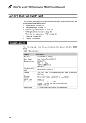
Specifications Feature Processor Core Chipset Bus architecture Graphic memory chip Display Standard memory CMOS RAM Hard disk drive Optical drive Description • Intel Chief River platform • Intel Panther Point HM76/70 • ...Lenovo IdeaPad Z500/P500 This chapter presents the following product-specific service references and product-specific parts information: •• "Specifications" on page 26 •• "Status indicators" on page 28 •• "Function key combinations" on page 29 •• "FRU replacement notices" on page 30 •• "Removing...
Specifications Feature Processor Core Chipset Bus architecture Graphic memory chip Display Standard memory CMOS RAM Hard disk drive Optical drive Description • Intel Chief River platform • Intel Panther Point HM76/70 • ...Lenovo IdeaPad Z500/P500 This chapter presents the following product-specific service references and product-specific parts information: •• "Specifications" on page 26 •• "Status indicators" on page 28 •• "Function key combinations" on page 29 •• "FRU replacement notices" on page 30 •• "Removing...
Hardware Maintenance Manual
Page 45
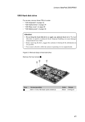
... data. • Before removing the drive, suggest the customer to physical shock. Improper handling can cause damages and permanent loss of hard disk drive Remove the four screws 1. 1 1 1 Step 1 Screw (quantity) M2.5 × 3 mm, flat-head, nylok-coated (4) Color Torque Black 8.03 kg-cm 41 Figure 5. Lenovo IdeaPad Z500/P500 1050 Hard disk drive For access, remove these FRUs in suspend...
... data. • Before removing the drive, suggest the customer to physical shock. Improper handling can cause damages and permanent loss of hard disk drive Remove the four screws 1. 1 1 1 Step 1 Screw (quantity) M2.5 × 3 mm, flat-head, nylok-coated (4) Color Torque Black 8.03 kg-cm 41 Figure 5. Lenovo IdeaPad Z500/P500 1050 Hard disk drive For access, remove these FRUs in suspend...
Hardware Maintenance Manual
Page 46
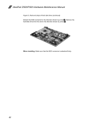
Remove the hard disk drive from the slot in the direction shown by arrow 3. 3 2 When installing: Make sure that the HDD connector is attached firmly. 42 Removal steps of hard disk drive (continued) Detach the HDD connector in the direction shown by arrow 2. IdeaPad Z500/P500 Hardware Maintenance Manual Figure 5.
Remove the hard disk drive from the slot in the direction shown by arrow 3. 3 2 When installing: Make sure that the HDD connector is attached firmly. 42 Removal steps of hard disk drive (continued) Detach the HDD connector in the direction shown by arrow 2. IdeaPad Z500/P500 Hardware Maintenance Manual Figure 5.
Hardware Maintenance Manual
Page 52
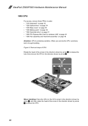
IdeaPad Z500/P500 Hardware Maintenance Manual 1090 CPU For access, remove these FRUs in the direction shown by arrow b to release the lock, then remove the CPU in the direction shown by arrow 2. 1 a b 2 When installing: Place the CPU on page 46 Attention: CPU is extremely sensitive. Removal steps of CPU Rotate the head of ... page 34 •• "1030 Base cover" on page 36 •• "1040 Battery pack" on page 39 •• "1050 Hard disk drive" on page 41 •• "1060 PCI Express Mini Card for wireless LAN" on page 43 •• "1080 Fan assembly and Heat Sink ...
IdeaPad Z500/P500 Hardware Maintenance Manual 1090 CPU For access, remove these FRUs in the direction shown by arrow b to release the lock, then remove the CPU in the direction shown by arrow 2. 1 a b 2 When installing: Place the CPU on page 46 Attention: CPU is extremely sensitive. Removal steps of CPU Rotate the head of ... page 34 •• "1030 Base cover" on page 36 •• "1040 Battery pack" on page 39 •• "1050 Hard disk drive" on page 41 •• "1060 PCI Express Mini Card for wireless LAN" on page 43 •• "1080 Fan assembly and Heat Sink ...
Hardware Maintenance Manual
Page 53
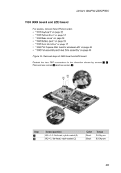
... (quantity) M2 × 2.5, flat-head, nylok-coated (2) M2 × 3, flat-head, nylok-coated (2) Color Black Black Torque 3.62 kg-cm 8.03 kg-cm 49 Removal steps of ODD board and LED board Detach the two FPC connectors in order: •• "1010 Keyboard" on page 32 •• "1020 Optical...•• "1050 Hard disk drive" on page 41 •• "1060 PCI Express Mini Card for wireless LAN" on page 43 •• "1080 Fan assembly and Heat Sink assembly" on page 46 Figure 10. Lenovo IdeaPad Z500/P500 1100 ODD board and LED board For access, remove these FRUs in the ...
... (quantity) M2 × 2.5, flat-head, nylok-coated (2) M2 × 3, flat-head, nylok-coated (2) Color Black Black Torque 3.62 kg-cm 8.03 kg-cm 49 Removal steps of ODD board and LED board Detach the two FPC connectors in order: •• "1010 Keyboard" on page 32 •• "1020 Optical...•• "1050 Hard disk drive" on page 41 •• "1060 PCI Express Mini Card for wireless LAN" on page 43 •• "1080 Fan assembly and Heat Sink assembly" on page 46 Figure 10. Lenovo IdeaPad Z500/P500 1100 ODD board and LED board For access, remove these FRUs in the ...
Hardware Maintenance Manual
Page 55
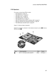
...•• "1050 Hard disk drive" on page 41 •• "1060 PCI Express Mini Card for wireless LAN" on page 43 •• "1080 Fan assembly and Heat Sink assembly" on page 46 •• "1100 ODD board and LED board" on page 49 Figure 11. Remove the four screws 2. 2... 2 2 1 Step 2 Screw (quantity) M2 × 5.7, flat-head, nylok-coated (4) Color Black Torque 8.03 kg-cm 51 Lenovo IdeaPad Z500/P500 1110 Speakers For access, remove these FRUs in the direction shown by arrow 1.
...•• "1050 Hard disk drive" on page 41 •• "1060 PCI Express Mini Card for wireless LAN" on page 43 •• "1080 Fan assembly and Heat Sink assembly" on page 46 •• "1100 ODD board and LED board" on page 49 Figure 11. Remove the four screws 2. 2... 2 2 1 Step 2 Screw (quantity) M2 × 5.7, flat-head, nylok-coated (4) Color Black Torque 8.03 kg-cm 51 Lenovo IdeaPad Z500/P500 1110 Speakers For access, remove these FRUs in the direction shown by arrow 1.
Hardware Maintenance Manual
Page 57
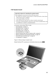
... such as an ESD mat or conductive corrugated material. Lenovo IdeaPad Z500/P500 1120 System board Important notices for handling the system board: When handling the system board, bear the following in order: •• "1010 Keyboard" on page 32 •• "1020 Optical drive" on page 34 •• "1030 Base cover..." on page 51 Figure 12. Removal steps of any kind. • In the whole process, make sure not to drop or stack the system board. • If you put a system board down, make sure to drop the system board on a bench top that has a hard surface, such as metal, wood,...
... such as an ESD mat or conductive corrugated material. Lenovo IdeaPad Z500/P500 1120 System board Important notices for handling the system board: When handling the system board, bear the following in order: •• "1010 Keyboard" on page 32 •• "1020 Optical drive" on page 34 •• "1030 Base cover..." on page 51 Figure 12. Removal steps of any kind. • In the whole process, make sure not to drop or stack the system board. • If you put a system board down, make sure to drop the system board on a bench top that has a hard surface, such as metal, wood,...
Hardware Maintenance Manual
Page 59
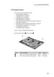
... kg-cm 55 Lenovo IdeaPad Z500/P500 1130 Keyboard bezel For access, remove these FRUs in order: •• "1010 Keyboard" on page 32 •• "1020 Optical drive" on page 34 •• "1030 Base cover" on page 36 •• "1040 Battery pack" on page 39 •• "1050 Hard disk drive" on page 41...
... kg-cm 55 Lenovo IdeaPad Z500/P500 1130 Keyboard bezel For access, remove these FRUs in order: •• "1010 Keyboard" on page 32 •• "1020 Optical drive" on page 34 •• "1030 Base cover" on page 36 •• "1040 Battery pack" on page 39 •• "1050 Hard disk drive" on page 41...
Hardware Maintenance Manual
Page 61
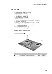
Lenovo IdeaPad Z500/P500 1140 LCD unit For access, remove these FRUs in order: •• "1010 Keyboard" on page 32 •• "1020 Optical drive" on page 34 •• "1030 Base cover" on page 36 •• "1040 Battery pack" on page 39 •• "1050 Hard disk drive" on page 41 ..."1110 Speakers" on page 51 •• "1120 System board" on page 53 •• "1130 Keyboard bezel" on page 55 Figure 14. Removal steps of LCD unit Remove the five screws 1. 1 1 Step 1 Screw (quantity) M2.5 × 6 mm, flat-head, nylok-coated (5) Color Torque Black 8.03 kg-cm...
Lenovo IdeaPad Z500/P500 1140 LCD unit For access, remove these FRUs in order: •• "1010 Keyboard" on page 32 •• "1020 Optical drive" on page 34 •• "1030 Base cover" on page 36 •• "1040 Battery pack" on page 39 •• "1050 Hard disk drive" on page 41 ..."1110 Speakers" on page 51 •• "1120 System board" on page 53 •• "1130 Keyboard bezel" on page 55 Figure 14. Removal steps of LCD unit Remove the five screws 1. 1 1 Step 1 Screw (quantity) M2.5 × 6 mm, flat-head, nylok-coated (5) Color Torque Black 8.03 kg-cm...
Hardware Maintenance Manual
Page 63
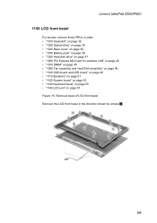
Lenovo IdeaPad Z500/P500 1150 LCD front bezel For access, remove these FRUs in the direction shown by arrows 1. 1 1 1 1 59 Removal steps of LCD front bezel Remove the LCD front bezel in order: •• "1010 Keyboard" on page 32 •• "1020 Optical drive" on page 34 •• "...1030 Base cover" on page 36 •• "1040 Battery pack" on page 39 •• "1050 Hard disk drive" ...
Lenovo IdeaPad Z500/P500 1150 LCD front bezel For access, remove these FRUs in the direction shown by arrows 1. 1 1 1 1 59 Removal steps of LCD front bezel Remove the LCD front bezel in order: •• "1010 Keyboard" on page 32 •• "1020 Optical drive" on page 34 •• "...1030 Base cover" on page 36 •• "1040 Battery pack" on page 39 •• "1050 Hard disk drive" ...
Hardware Maintenance Manual
Page 64
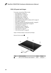
IdeaPad Z500/P500 Hardware Maintenance Manual 1160 LCD panel and hinges For access, remove these FRUs in order: •• "1010 Keyboard" on page 32 •• "1020 Optical drive" on page 34 •• "1030 Base cover" on page 36 •• "1040 Battery pack" on page 39 •• "1050 Hard disk drive...on page 55 •• "1140 LCD unit" on page 57 •• "1150 LCD front bezel" on page 59 Figure 16. Removal steps of LCD panel and hinges Remove the four screws 1. 1 1 1 1 Step 1 Screw (quantity) M2 × 2.5 mm, flat-head, nylok-coated (4) Color Black ...
IdeaPad Z500/P500 Hardware Maintenance Manual 1160 LCD panel and hinges For access, remove these FRUs in order: •• "1010 Keyboard" on page 32 •• "1020 Optical drive" on page 34 •• "1030 Base cover" on page 36 •• "1040 Battery pack" on page 39 •• "1050 Hard disk drive...on page 55 •• "1140 LCD unit" on page 57 •• "1150 LCD front bezel" on page 59 Figure 16. Removal steps of LCD panel and hinges Remove the four screws 1. 1 1 1 1 Step 1 Screw (quantity) M2 × 2.5 mm, flat-head, nylok-coated (4) Color Black ...
Hardware Maintenance Manual
Page 67
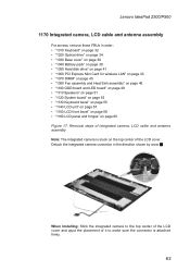
... page 34 •• "1030 Base cover" on page 36 •• "1040 Battery pack" on page 39 •• "1050 Hard disk drive" on page 41 •• "1060 PCI Express Mini Card for wireless LAN" on page 43 •• "1070 DIMM" on page 45 •• "... bezel" on page 59 •• "1160 LCD panel and hinges" on the top center of the LCD cover. Lenovo IdeaPad Z500/P500 1170 Integrated camera, LCD cable and antenna assembly For access, remove these FRUs in the direction shown by arow 1. 1 When installing: Stick the integrated camera to the top center of the...
... page 34 •• "1030 Base cover" on page 36 •• "1040 Battery pack" on page 39 •• "1050 Hard disk drive" on page 41 •• "1060 PCI Express Mini Card for wireless LAN" on page 43 •• "1070 DIMM" on page 45 •• "... bezel" on page 59 •• "1160 LCD panel and hinges" on the top center of the LCD cover. Lenovo IdeaPad Z500/P500 1170 Integrated camera, LCD cable and antenna assembly For access, remove these FRUs in the direction shown by arow 1. 1 When installing: Stick the integrated camera to the top center of the...


