
User Guide
Page 7
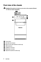
Power button Hard disk drive indicator Memory card reader (selected models only) USB connectors Headphone connector Microphone connector Optical Drive (selected models only) 2 User Guide Front view of the chassis Attention: Be careful not to block any air vents on the computer. Blocked air vents can cause overheating.
Power button Hard disk drive indicator Memory card reader (selected models only) USB connectors Headphone connector Microphone connector Optical Drive (selected models only) 2 User Guide Front view of the chassis Attention: Be careful not to block any air vents on the computer. Blocked air vents can cause overheating.

User Guide
Page 11
... connected between the audio line-out connector of the device and the audio line-in connector of the connectors described in connector on a media card. Memory card reader Use to receive audio signals from the computer to music or other devices that requires a USB connection. USB connector Use this connector to...
... connected between the audio line-out connector of the device and the audio line-in connector of the connectors described in connector on a media card. Memory card reader Use to receive audio signals from the computer to music or other devices that requires a USB connection. USB connector Use this connector to...

User Guide
Page 36
Hardware Replacement Guide This chapter contains the following topics: Locating components Identifying parts on the system board Removing the computer cover Removing and replacing the front bezel Replacing a memory module Replacing the hard disk drive Replacing an optical drive Replacing a PCI express adapter Replacing the keyboard and mouse Completing the installation User Guide 31
Hardware Replacement Guide This chapter contains the following topics: Locating components Identifying parts on the system board Removing the computer cover Removing and replacing the front bezel Replacing a memory module Replacing the hard disk drive Replacing an optical drive Replacing a PCI express adapter Replacing the keyboard and mouse Completing the installation User Guide 31

User Guide
Page 37
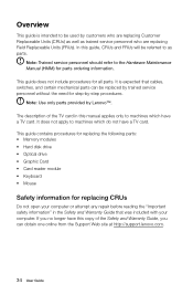
... mechanical parts can obtain one online from the Support Web site at http://support.lenovo.com. 32 User Guide It is intended to be used by Lenovo™. This guide contains procedures for replacing the following parts: • Memory modules • Hard disk drive • Optical drive • Graphic Card • Card reader...
... mechanical parts can obtain one online from the Support Web site at http://support.lenovo.com. 32 User Guide It is intended to be used by Lenovo™. This guide contains procedures for replacing the following parts: • Memory modules • Hard disk drive • Optical drive • Graphic Card • Card reader...

User Guide
Page 39
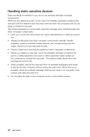
... a smooth, level surface and place the part on it. • Do not place the part on the computer for at least two seconds. Handle adapters, memory modules, system boards, and microprocessors by the edges. Never touch any exposed circuitry. • Prevent others from touching the parts and other computer components. •...
... a smooth, level surface and place the part on it. • Do not place the part on the computer for at least two seconds. Handle adapters, memory modules, system boards, and microprocessors by the edges. Never touch any exposed circuitry. • Prevent others from touching the parts and other computer components. •...

User Guide
Page 40
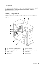
Locations This section provides illustrations to "Removing the computer cover". To remove the computer cover, refer to help you to locate the various components in your computer. Locating components The following illustration will help locate the various connectors, controls and components of the computer. Microprocessor fan and heatsink PCI express adapter card Power supply Optical drive Memory modules PCI express adapter connectors System fan Hard disk drive User Guide 35
Locations This section provides illustrations to "Removing the computer cover". To remove the computer cover, refer to help you to locate the various components in your computer. Locating components The following illustration will help locate the various connectors, controls and components of the computer. Microprocessor fan and heatsink PCI express adapter card Power supply Optical drive Memory modules PCI express adapter connectors System fan Hard disk drive User Guide 35

User Guide
Page 41
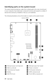
The following illustrations show the locations of devices that are factory-installed or that you can install later. Lenovo H505 12 3 4 5 6 13 12 11 10 9 8 7 Microprocessor and heat sink Memory slots (2) Thermal sensor header Battery Mini PCI-E slot Microprocessor fan header Power connector Front panel connector SATA connectors (2) Front USB connectors (2) 36 User...
The following illustrations show the locations of devices that are factory-installed or that you can install later. Lenovo H505 12 3 4 5 6 13 12 11 10 9 8 7 Microprocessor and heat sink Memory slots (2) Thermal sensor header Battery Mini PCI-E slot Microprocessor fan header Power connector Front panel connector SATA connectors (2) Front USB connectors (2) 36 User...

User Guide
Page 44
.... 2. Refer to the computer. This includes power cords, input/output (I/O) cables, and any media (disks, CDs, or memory cards) from electrical outlets. 3. User Guide 39 Replacing hardware Note: Use only parts provided by Lenovo. Removing the computer cover Attention: Turn off the computer and all cables attached to "Locating connectors on the...
.... 2. Refer to the computer. This includes power cords, input/output (I/O) cables, and any media (disks, CDs, or memory cards) from electrical outlets. 3. User Guide 39 Replacing hardware Note: Use only parts provided by Lenovo. Removing the computer cover Attention: Turn off the computer and all cables attached to "Locating connectors on the...

User Guide
Page 47
... correctly with the connector key on the system board. Locate the memory module connectors. Push the memory module straight down into the connector until the retaining clips close. 5. Replacing a memory module To replace a memory module: 1. Remove the computer cover. Remove the memory module being replaced by opening the retaining clips as shown. 4. Refer to "Completing...
... correctly with the connector key on the system board. Locate the memory module connectors. Push the memory module straight down into the connector until the retaining clips close. 5. Replacing a memory module To replace a memory module: 1. Remove the computer cover. Remove the memory module being replaced by opening the retaining clips as shown. 4. Refer to "Completing...

User Guide
Page 53
... same method. 48 User Guide Locate the connector for the keyboard. Disconnect the failing keyboard cable from electrical outlets. 3. Remove any media (disks, CDs, or memory cards) from the drives, shut down the operating system, and turn off the computer and all power cords from the computer and connect the new...
... same method. 48 User Guide Locate the connector for the keyboard. Disconnect the failing keyboard cable from electrical outlets. 3. Remove any media (disks, CDs, or memory cards) from the drives, shut down the operating system, and turn off the computer and all power cords from the computer and connect the new...
Safety and Warranty guide
Page 9
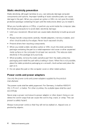
... boards by the edges. Doing so can cause the cord to the part. Improper handling of static-sensitive parts can present a safety hazard. Handle adapters, memory modules, and other metal surface.
... boards by the edges. Doing so can cause the cord to the part. Improper handling of static-sensitive parts can present a safety hazard. Handle adapters, memory modules, and other metal surface.
Lenovo H5 Series User Guide
Page 7
Power button Hard disk drive indicator Memory card reader (selected models only) USB connectors Headphone connector Microphone connector Optical Drive (selected models only) 2 User Guide Blocked air vents can cause overheating. Front view of the chassis Attention: Be careful not to block any air vents on the computer.
Power button Hard disk drive indicator Memory card reader (selected models only) USB connectors Headphone connector Microphone connector Optical Drive (selected models only) 2 User Guide Blocked air vents can cause overheating. Front view of the chassis Attention: Be careful not to block any air vents on the computer.
Lenovo H5 Series User Guide
Page 13
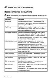
... of this section. Attention: Do not open the WiFi antenna cover. Audio line-in connector Used to attach a DVI monitor or other external recording device. Memory card reader Use to the power cable. Power connector Connect to view and share digital photos, music, and videos, stored on a stereo system or other...
... of this section. Attention: Do not open the WiFi antenna cover. Audio line-in connector Used to attach a DVI monitor or other external recording device. Memory card reader Use to the power cable. Power connector Connect to view and share digital photos, music, and videos, stored on a stereo system or other...
Lenovo H5 Series User Guide
Page 38
Hardware Replacement Guide This chapter contains the following topics: Locating components Identifying parts on the system board Removing the computer cover Removing and replacing the front bezel Replacing a memory module Replacing the hard disk drive Replacing an optical drive Replacing a PCI express adapter Replacing the keyboard and mouse Completing the installation User Guide 33
Hardware Replacement Guide This chapter contains the following topics: Locating components Identifying parts on the system board Removing the computer cover Removing and replacing the front bezel Replacing a memory module Replacing the hard disk drive Replacing an optical drive Replacing a PCI express adapter Replacing the keyboard and mouse Completing the installation User Guide 33
Lenovo H5 Series User Guide
Page 39
...the Safety and Warranty Guide that cables, switches, and certain mechanical parts can obtain one online from the Support Web site at http://support.lenovo.com. 34 User Guide Note: Use only parts provided by -step procedures. It is intended to be used by customers who are ... Units (FRUs). Overview This guide is expected that was included with your computer. This guide contains procedures for replacing the following parts: • Memory modules • Hard disk drive • Optical drive • Graphic Card • Card reader module • Keyboard • Mouse Safety information ...
...the Safety and Warranty Guide that cables, switches, and certain mechanical parts can obtain one online from the Support Web site at http://support.lenovo.com. 34 User Guide Note: Use only parts provided by -step procedures. It is intended to be used by customers who are ... Units (FRUs). Overview This guide is expected that was included with your computer. This guide contains procedures for replacing the following parts: • Memory modules • Hard disk drive • Optical drive • Graphic Card • Card reader module • Keyboard • Mouse Safety information ...
Lenovo H5 Series User Guide
Page 41
.... • Before you replace a new part, touch the antistatic package containing the part to a metal expansion slot cover or other computer components carefully. Handle adapters, memory modules, system boards, and microprocessors by the edges. Handling static-sensitive devices Static electricity is not possible, place the antistatic package that the part came...
.... • Before you replace a new part, touch the antistatic package containing the part to a metal expansion slot cover or other computer components carefully. Handle adapters, memory modules, system boards, and microprocessors by the edges. Handling static-sensitive devices Static electricity is not possible, place the antistatic package that the part came...
Lenovo H5 Series User Guide
Page 42
Microprocessor fan and heatsink PCI express adapter card Power supply Optical drive Memory modules PCI express adapter connectors System fan Hard disk drive User Guide 37 Locating components The following illustration will help locate the various connectors, controls and components of the computer. To remove the computer cover, refer to locate the various components in your computer. Locations This section provides illustrations to help you to "Removing the computer cover".
Microprocessor fan and heatsink PCI express adapter card Power supply Optical drive Memory modules PCI express adapter connectors System fan Hard disk drive User Guide 37 Locating components The following illustration will help locate the various connectors, controls and components of the computer. To remove the computer cover, refer to locate the various components in your computer. Locations This section provides illustrations to help you to "Removing the computer cover".
Lenovo H5 Series User Guide
Page 43
... parts on the system board The system board (sometimes called the motherboard) is the main circuit board in your computer. Lenovo H505 12 3 4 5 6 13 12 11 10 9 8 7 Microprocessor and heat sink Memory slots (2) Thermal sensor header Battery Mini PCI-E slot Microprocessor fan header Power connector Front panel connector SATA connectors (2) Front USB...
... parts on the system board The system board (sometimes called the motherboard) is the main circuit board in your computer. Lenovo H505 12 3 4 5 6 13 12 11 10 9 8 7 Microprocessor and heat sink Memory slots (2) Thermal sensor header Battery Mini PCI-E slot Microprocessor fan header Power connector Front panel connector SATA connectors (2) Front USB...

Lenovo H5 Series User Guide
Page 48
... minutes to the computer. Disconnect all attached devices. 2. User Guide 43 Replacing hardware Note: Use only parts provided by Lenovo. This includes power cords, input/output (I/O) cables, and any media (disks, CDs, or memory cards) from electrical outlets. 3. Removing the computer cover Attention: Turn off the computer and all cables attached to...
... minutes to the computer. Disconnect all attached devices. 2. User Guide 43 Replacing hardware Note: Use only parts provided by Lenovo. This includes power cords, input/output (I/O) cables, and any media (disks, CDs, or memory cards) from electrical outlets. 3. Removing the computer cover Attention: Turn off the computer and all cables attached to...
Lenovo H5 Series User Guide
Page 51
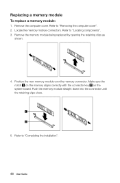
... the installation". 46 User Guide Position the new memory module over the memory connector. Push the memory module straight down into the connector until the retaining clips close. 5. Replacing a memory module To replace a memory module: 1. Remove the computer cover. Refer to "Removing the computer cover". 2. Remove the memory module being replaced by opening the retaining clips...
... the installation". 46 User Guide Position the new memory module over the memory connector. Push the memory module straight down into the connector until the retaining clips close. 5. Replacing a memory module To replace a memory module: 1. Remove the computer cover. Refer to "Removing the computer cover". 2. Remove the memory module being replaced by opening the retaining clips...


