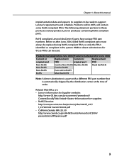
Lenovo H4 Series Hardware Maintenance Manual V2.0
Page 2
... ii Locations 34 Locating components 34 Locating connectors on the front of the computer 35 Locating connectors on the rear of the computer 36 Identifying parts on the system board 38 Chapter 9. Hardware Maintenance Manual Exiting from the Setup Utility program 27 Chapter 7. Additional Service Information (Type G41)......61 Power management...
Lenovo H4 Series Hardware Maintenance Manual V2.0
Page 3
This manual includes a complete FRU part number listing for Lenovo IdeaCentre K computers listed on the cover. It is invalid for those machines which have TV card. Before servicing a Lenovo product, be sure to read the Safety Information. The description of the instructions. Veuillez lire toutes les ...It is intended only for the machines which do not have the TV card. If you have internet access, FRU part numbers are familiar with Lenovo computer products. About this book before performing any of the TV card in dieser Dokumentation, bevor Sie irgendwelche Vorgä...
Lenovo H4 Series Hardware Maintenance Manual V2.0
Page 4
... must also be used to RoHS compliance well before June 2006 are not required to http://www.lenovo.com/support. 2. Under Browse by description, with your browser to have RoHS compliant parts. So, if the parts are returned in Electrical and Electronic Equipment Directive (2002/95/EC) is displayed. The list of key...
Lenovo H4 Series Hardware Maintenance Manual V2.0
Page 5
... 2006, failed RoHS compliant parts must always be RoHS Note: A direct substitution is a part with a different FRU part number that is automatically shipped by the distribution center at the time of order. RoHS compliant Lenovo IdeaCentre K parts have unique FRU part numbers. Before or after ...June 2006 Current or Replacement Current or Replacement original part FRU original part FRU Non-RoHS Can be Non-RoHS Must be RoHS Must...
Lenovo H4 Series Hardware Maintenance Manual V2.0
Page 6
... that other service representatives and the customer's personnel are not in a hazardous position. •• Place removed covers and other parts in a safe place, away from the muscles in the moving parts of a machine. Distribute the weight of your necktie or scarf inside clothing or fasten it . •• Do not wear...
Lenovo H4 Series Hardware Maintenance Manual V2.0
Page 8
... working with very high voltages; Remember: There must be a complete circuit to cause electrical shock. First, check that has exposed electrical circuits, observe the following parts with the power on suitable rubber mats (obtained locally, if necessary) to switch off . •• Always look carefully for possible hazards in the safety...
Lenovo H4 Series Hardware Maintenance Manual V2.0
Page 9
... must not be the appropriate type as to protect users and service personnel from injury. The power cord should be and whether you in the parts listings. c. Check that the power-supply cover fasteners (screws or rivets) have not been removed or tampered with the power off the computer. Begin the...
Lenovo H4 Series Hardware Maintenance Manual V2.0
Page 10
...at the same charge. Attach the ESD ground clip to electrostatic discharge (ESD). When handling ESD-sensitive parts: •• Keep the parts in charge between objects. Use an ESD common ground or reference point when working on ac-operated computers....sensitive to any frame ground, ground braid, or green-wire ground. - Hardware Maintenance Manual Handling electrostatic discharge-sensitive devices Any computer part containing transistors or integrated circuits (ICs) should be verified by equalizing the charge so that meets the specific service requirement. Notes:...
Lenovo H4 Series Hardware Maintenance Manual V2.0
Page 12
...CAUTION: When laser products (such as required by the manufacturer. Hardware Maintenance Manual CAUTION: When replacing the lithium battery, use only Part Number 33F8354 or an equivalent type battery recommended by local ordinances or regulations. If your system has a module containing a lithium ...battery, replace it only with optical instruments, and avoid direct exposure to hazardous laser radiation. There are no serviceable parts inside the device. •• Use of controls or adjustments or performance of procedures other than 100°C (212°F) ...
Lenovo H4 Series Hardware Maintenance Manual V2.0
Page 30
.... • If you decide which FRUs to help you did not receive any error message look for a description of your error symptoms in the first part of this index, go to -FRU index lists error symptoms and possible causes. Error FRU/Action The start -up drive is listed first. Hard disk...
Lenovo H4 Series Hardware Maintenance Manual V2.0
Page 32
...) • If beep codes are not generated when all other expansion cards are absent, consult your system manufacturer. If the video adapter is an integrated part of the add-in cards 7 beeps is an Display memory error (system video add-in base memory (first 64KB block) 3 beeps Base memory read/write...
Lenovo H4 Series Hardware Maintenance Manual V2.0
Page 40
... with a graphics card) PCI Express x1 adapter connector (Some models are factory-installed or that are equipped with a WIFI card or TV tuner card) Identifying parts on your computer. The following illustrations show the locations of parts on the system board (Only one of devices that you can install later.
Lenovo H4 Series Hardware Maintenance Manual V2.0
Page 43
... the computer cover: 1. This includes power cords, input/output (I/O) cables, and any other cables that secure the computer cover at : http://consumersupport.lenovo.com Note Use only parts provided by Lenovo. Replacing hardware Attention Do not remove the computer cover or attempt any media (disks, CDs, or memory cards) from electrical outlets. 3. Remove...
Lenovo H4 Series Hardware Maintenance Manual V2.0
Page 48
...computer cover or attempt any repairs before reading the "Important safety information" in the Safety and Warranty Guide that secure the optical drive to "Identifying parts on the system board". 8. To obtain copies of the chassis. 46 Remove the computer cover. Refer to the "Completing the installation". Push ... optical drive straight out of the front of the Safety and Warranty Guide or HMM, go to the Support Web site at: http://consumersupport.lenovo.com To replace an optical drive 1. Remove the two screws that was included with your computer or in the drive bay. 7. Screw the...
Lenovo H4 Series Hardware Maintenance Manual V2.0
Page 50
... Hardware Maintenance Manual (HMM) for the computer. Remove the computer cover. Refer to the Support Web site at: http://consumersupport.lenovo.com To replace the heatsink assembly: 1. Hardware Maintenance Manual 3. To obtain copies of the Safety and Warranty Guide or HMM, go to... "Identifying parts on its side. 3. Refer to "Completing the installation". Refer to "Removing the computer cover". 2. Disconnect the heatsink assembly cable from...
Lenovo H4 Series Hardware Maintenance Manual V2.0
Page 56
Locate the system fan assembly. Reconnect all the relative parts back. 12. To obtain copies of the chassis. 9. Align then insert the new motherboard and screw it in the Hardware Maintenance Manual (HMM) for the ... and Warranty Guide that was included with your computer or in . 10. Refer to "Identifying parts on the system board". 54 Refer to "Removing the computer cover". 2. Refer to the Support Web site at: http://consumersupport.lenovo.com To replace the system fan assembly: 1. Remove the computer cover. Slide and then lift...
Lenovo H4 Series Hardware Maintenance Manual V2.0
Page 57
Refer to"Identifying parts on the chassis and then push the rubber mounts through the holes. 55 Pull the system fan assembly out of the system fan assembly with the holes on the system board". 4. Disconnect the system fan assembly cable from the system board. Replacing hardware 3. Install the new system fan assembly by aligning the rubber mounts of the chassis. 5. Chapter 9.
Lenovo H4 Series Hardware Maintenance Manual V2.0
Page 61
Completing the installation After replacing a new part or parts, you may be connected to the "Completing the parts replacement". Refer to "Locating connectors on the rear of the computer" and "Locating connectors on the chassis back into position. Make sure that was replaced... location of the computer". Screw back the two screws on the front of the various components. 2. Locate the speaker. In addition, depending on the part that all components have been reassembled correctly and that the rail guides on the chassis so that no tools or loose screws are routed correctly...
Lenovo H4 Series Hardware Replacement Guide V3.0
Page 4
Contents Overview 1 Chapter 1 Locations 5 Locating components 5 Locating connectors on the front of the computer 6 Locating connectors on the rear of the computer 7 Identifying parts on the system board 13 Chapter 2 Replacing hardware 19 Removing the computer cover 19 Removing and replacing the front bezel 21 Replacing a memory module 22 Replacing the hard disk drive 23 Replacing an optical drive 24 Replacing the heatsink assembly 26 Replacing a PCI or AGP adapter 28 Replacing the keyboard and mouse 30 Completing the installation 31 Chapter 3 Appendix 33
Lenovo H4 Series Hardware Replacement Guide V3.0
Page 6
... CRUs and FRUs will be referred to the Hardware Maintenance Manual (HMM) for parts ordering information. If you no longer have a TV card. The description of the Safety and Warranty Guide, you can be used by Lenovo™. In this copy of the TV card in the Safety and Warranty Guide... that cables, switches, and certain mechanical parts can obtain one online from the Support Web site at http://consumersupport...