Lenovo C225\C320\C325 Hardware Maintenance Manual
Page 3
... cover 37 Replacing the system fan 38 Replacing the TV tuner card 40 Replacing the WLAN card 41 Replacing the heatsink 42 Replacing the CPU 44 Replacing the rear I/O module 46 Replacing the speaker system 48 Replacing the motherboard 49 Replacing the camera 51 Replacing the front indicator and power button board 52 Replacing the front function board 53 Replacing the LED panel 54 Chapter 8. Using the Setup Utility. . . 13 Starting the Setup Utility program 13 Viewing and changing settings 13 Using passwords 13 Using Device 15 Selecting a startup device...
... cover 37 Replacing the system fan 38 Replacing the TV tuner card 40 Replacing the WLAN card 41 Replacing the heatsink 42 Replacing the CPU 44 Replacing the rear I/O module 46 Replacing the speaker system 48 Replacing the motherboard 49 Replacing the camera 51 Replacing the front indicator and power button board 52 Replacing the front function board 53 Replacing the LED panel 54 Chapter 8. Using the Setup Utility. . . 13 Starting the Setup Utility program 13 Viewing and changing settings 13 Using passwords 13 Using Device 15 Selecting a startup device...
Lenovo C225\C320\C325 Hardware Maintenance Manual
Page 9
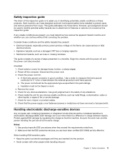
... exterior covers for any unsafe conditions are present, you must not be and whether you use have not been removed or tampered with. Disconnect the power cord. 3. Check inside the unit for worn, frayed, or pinched cables. 8. Protect against ESD damage by this inspection guide is a difference in charge between the external ground pin and frame ground. Use product-specific ESD...
... exterior covers for any unsafe conditions are present, you must not be and whether you use have not been removed or tampered with. Disconnect the power cord. 3. Check inside the unit for worn, frayed, or pinched cables. 8. Protect against ESD damage by this inspection guide is a difference in charge between the external ground pin and frame ground. Use product-specific ESD...
Lenovo C225\C320\C325 Hardware Maintenance Manual
Page 15
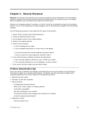
... information available when requesting assistance from Service Support and Engineering functions. • Machine type and model • Processor or hard disk upgrades • Failure symptom Do diagnostics indicate a failure? Be extremely careful during write operations such as copying, saving, or formatting. General error messages appear if a problem or conflict is displayed, continue at step 7. 7. Chapter 4. Problem determination tips Due to the variety of hardware and software combinations that software package.
... information available when requesting assistance from Service Support and Engineering functions. • Machine type and model • Processor or hard disk upgrades • Failure symptom Do diagnostics indicate a failure? Be extremely careful during write operations such as copying, saving, or formatting. General error messages appear if a problem or conflict is displayed, continue at step 7. 7. Chapter 4. Problem determination tips Due to the variety of hardware and software combinations that software package.
Lenovo C225\C320\C325 Hardware Maintenance Manual
Page 17
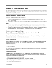
... menu lists items that cannot be easily compromised. When working with the Setup Utility program menu, you hear multiple beeps, release the F1 key. However, if you type your user name © Copyright Lenovo 13 Password considerations A password can set any similar settings in length • Contain at least one alphabetic character and one numeric character • Setup Utility program and hard disk drive passwords are using a USB keyboard and the Setup Utility program does not display using . Starting...
... menu lists items that cannot be easily compromised. When working with the Setup Utility program menu, you hear multiple beeps, release the F1 key. However, if you type your user name © Copyright Lenovo 13 Password considerations A password can set any similar settings in length • Contain at least one alphabetic character and one numeric character • Setup Utility program and hard disk drive passwords are using a USB keyboard and the Setup Utility program does not display using . Starting...

Lenovo C225\C320\C325 Hardware Maintenance Manual
Page 19
... boot device. Select Exit. 4. Select USB Setup. 4. Selecting a startup device If your computer. 2. Turn off your computer does not start up (boot) from the Startup Device Menu and press Enter to Disable, the device of the following procedures to the following : 1. When the Startup Device Menu appears, release the F12 key. Using the Setup Utility 15 Select Save changes and Exit. Select the desired startup device from a device such as the CD-ROM, diskette, or hard disk as Audio Setup and Network Setup...
... boot device. Select Exit. 4. Select USB Setup. 4. Selecting a startup device If your computer. 2. Turn off your computer does not start up (boot) from the Startup Device Menu and press Enter to Disable, the device of the following procedures to the following : 1. When the Startup Device Menu appears, release the F12 key. Using the Setup Utility 15 Select Save changes and Exit. Select the desired startup device from a device such as the CD-ROM, diskette, or hard disk as Audio Setup and Network Setup...
Lenovo C225\C320\C325 Hardware Maintenance Manual
Page 22
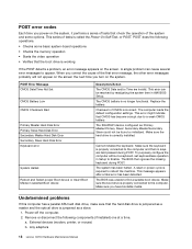
... Boot device or Insert Boot Media in AMI BIOS Setup. Replace the battery. Make sure the keyboard is required to a weak CMOS battery. The BIOS was unable to the computer and that CMOS has become corrupt due to reboot the machine. Any adapters 18 Lenovo C2/C3 Hardware Maintenance Manual When you correct the cause of the system and some basic system-board operations • Checks the memory operation • Starts the video operation • Verifies that the boot drive...
... Boot device or Insert Boot Media in AMI BIOS Setup. Replace the battery. Make sure the keyboard is required to a weak CMOS battery. The BIOS was unable to the computer and that CMOS has become corrupt due to reboot the machine. Any adapters 18 Lenovo C2/C3 Hardware Maintenance Manual When you correct the cause of the system and some basic system-board operations • Checks the memory operation • Starts the video operation • Verifies that the boot drive...
Lenovo C225\C320\C325 Hardware Maintenance Manual
Page 26
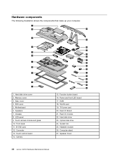
...and glass 10. Touch control board 14. Hard disk drive 23. Converter 13. Function button board 16. RAM 18. WLAN card 19. Rear I /O Board 21. Power and front LED board 17. Rear I /O module 22. Speaker Cover 22 Lenovo C2/C3 Hardware Maintenance Manual EMI cover 5. LED panel 9. B-CAS card 12. Front bezel 11. Speakers 7. TV turner card 20. Hardware components The following illustration shows the components that make up your computer. 1 2 27 3 4 5 6 7 8 9 10 11 1. Hard disk drive cover 2. Memory cover 3. Motherboard 6. Chassis 8. Camera 26 25...
...and glass 10. Touch control board 14. Hard disk drive 23. Converter 13. Function button board 16. RAM 18. WLAN card 19. Rear I /O Board 21. Power and front LED board 17. Rear I /O module 22. Speaker Cover 22 Lenovo C2/C3 Hardware Maintenance Manual EMI cover 5. LED panel 9. B-CAS card 12. Front bezel 11. Speakers 7. TV turner card 20. Hardware components The following illustration shows the components that make up your computer. 1 2 27 3 4 5 6 7 8 9 10 11 1. Hard disk drive cover 2. Memory cover 3. Motherboard 6. Chassis 8. Camera 26 25...
Lenovo C225\C320\C325 Hardware Maintenance Manual
Page 40
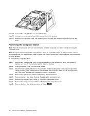
... computer. Remove the hard disk drive connector as shown. 36 Lenovo C2/C3 Hardware Maintenance Manual Disconnect all cables attached to "Replacing the hard disk drive". Refer to the new converter board. Step 12. Lenovo recommends that are connected to place the computer face-down before removing the computer cover. Step 7. Remove the optical drive. To remove the computer stand Step 1. Step 10. Connect the cables to "Replacing the optical drive". Reattach the computer cover, the speaker cover, the hard disk drive cover and the optical disk drive. Note...
... computer. Remove the hard disk drive connector as shown. 36 Lenovo C2/C3 Hardware Maintenance Manual Disconnect all cables attached to "Replacing the hard disk drive". Refer to the new converter board. Step 12. Lenovo recommends that are connected to place the computer face-down before removing the computer cover. Step 7. Remove the optical drive. To remove the computer stand Step 1. Step 10. Connect the cables to "Replacing the optical drive". Reattach the computer cover, the speaker cover, the hard disk drive cover and the optical disk drive. Note...
Lenovo C225\C320\C325 Hardware Maintenance Manual
Page 44
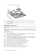
... other damage. Step 9. Refer to "Replacing the hard disk drive". Refer to "Replacing the optical drive". Step 7. Disconnect the antenna cable from scratches or other cables that are connected to protect the computer screen from the TV tuner card. Line up the new system fan then secure it from the card port. 40 Lenovo C2/C3 Hardware Maintenance Manual Remove the optical drive. Step 8. Step 6. Refer to the motherboard. Note: It may be helpful...
... other damage. Step 9. Refer to "Replacing the hard disk drive". Refer to "Replacing the optical drive". Step 7. Disconnect the antenna cable from scratches or other cables that are connected to protect the computer screen from the TV tuner card. Line up the new system fan then secure it from the card port. 40 Lenovo C2/C3 Hardware Maintenance Manual Remove the optical drive. Step 8. Step 6. Refer to the motherboard. Note: It may be helpful...
Lenovo C225\C320\C325 Hardware Maintenance Manual
Page 45
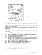
... the card port. Step 6. Remove the computer cover. Step 8. This includes power cords, input/output (I/O) cables, and any media (disks, CDs, or memory cards) from the WLAN card. Step 4. Refer to the motherboard. Step 7. Remove the EMI cover. Step 12. Lenovo recommends that are connected to protect the computer screen from scratches or other soft cloth to the computer. Remove the screw that secures the WLAN card to "Replacing the hard disk drive". Replacing hardware...
... the card port. Step 6. Remove the computer cover. Step 8. This includes power cords, input/output (I/O) cables, and any media (disks, CDs, or memory cards) from the WLAN card. Step 4. Refer to the motherboard. Step 7. Remove the EMI cover. Step 12. Lenovo recommends that are connected to protect the computer screen from scratches or other soft cloth to the computer. Remove the screw that secures the WLAN card to "Replacing the hard disk drive". Replacing hardware...
Lenovo C225\C320\C325 Hardware Maintenance Manual
Page 46
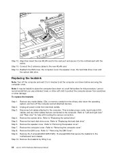
... electrical outlets. Lenovo recommends that you use a blanket, towel, or other damage. Remove the computer cover. Remove the EMI cover. Align then insert the new WLAN card to the card port and secure it up. 42 Lenovo C2/C3 Hardware Maintenance Manual Remove the speaker cover. Step 13. Refer to "Replacing the hard disk drive". Refer to "Left and right view" and "Rear view" for this procedure. Refer to the motherboard and chassis.
... electrical outlets. Lenovo recommends that you use a blanket, towel, or other damage. Remove the computer cover. Remove the EMI cover. Align then insert the new WLAN card to the card port and secure it up. 42 Lenovo C2/C3 Hardware Maintenance Manual Remove the speaker cover. Step 13. Refer to "Replacing the hard disk drive". Refer to "Left and right view" and "Rear view" for this procedure. Refer to the motherboard and chassis.
Lenovo C225\C320\C325 Hardware Maintenance Manual
Page 48
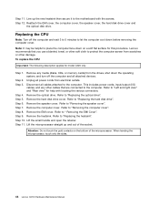
... any media (disks, CDs, or memory cards) from the drives, shut down before removing the computer cover. Remove the optical drive. Refer to the computer. Step 6. Lift the small handle and open the retainer. Attention: Do not touch the gold contacts on a soft flat surface for model C320 only. Step 4. Remove the hard disk drive cover. When handing the microprocessor, touch only the sides. 44 Lenovo C2/C3 Hardware Maintenance Manual...
... any media (disks, CDs, or memory cards) from the drives, shut down before removing the computer cover. Remove the optical drive. Refer to the computer. Step 6. Lift the small handle and open the retainer. Attention: Do not touch the gold contacts on a soft flat surface for model C320 only. Step 4. Remove the hard disk drive cover. When handing the microprocessor, touch only the sides. 44 Lenovo C2/C3 Hardware Maintenance Manual...
Lenovo C225\C320\C325 Hardware Maintenance Manual
Page 51
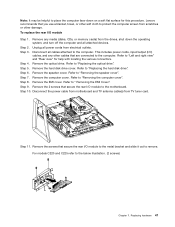
... attached devices. Lenovo recommends that you use a blanket, towel, or other soft cloth to protect the computer screen from TV tuner card. 1 2 1 3 3 Step 11. For models C220 and C225 refer to "Replacing the hard disk drive". Step 5. Refer to the below illustration. (2 screws) Chapter 7. Refer to "Replacing the optical drive". Disconnect the power cable from motherboard and TV antenna cable(s) from scratches or other cables that are connected to...
... attached devices. Lenovo recommends that you use a blanket, towel, or other soft cloth to protect the computer screen from TV tuner card. 1 2 1 3 3 Step 11. For models C220 and C225 refer to "Replacing the hard disk drive". Step 5. Refer to the below illustration. (2 screws) Chapter 7. Refer to "Replacing the optical drive". Disconnect the power cable from motherboard and TV antenna cable(s) from scratches or other cables that are connected to...
Lenovo C225\C320\C325 Hardware Maintenance Manual
Page 52
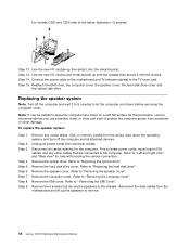
... down the operating system, and turn off the computer and wait 3 to 5 minutes to remove. 48 Lenovo C2/C3 Hardware Maintenance Manual Step 3. Step 6. Remove any other cables that you use a blanket, towel, or other damage. Remove the optical drive. Refer to " Removing the EMI Cover". Remove the hard disk drive cover. Refer to "Removing the computer cover". Step 5. Step 8. Step 9. This includes power cords, input/output (I/O) cables, and any media (disks, CDs, or memory cards) from scratches...
... down the operating system, and turn off the computer and wait 3 to 5 minutes to remove. 48 Lenovo C2/C3 Hardware Maintenance Manual Step 3. Step 6. Remove any other cables that you use a blanket, towel, or other damage. Remove the optical drive. Refer to " Removing the EMI Cover". Remove the hard disk drive cover. Refer to "Removing the computer cover". Step 5. Step 8. Step 9. This includes power cords, input/output (I/O) cables, and any media (disks, CDs, or memory cards) from scratches...
Lenovo C225\C320\C325 Hardware Maintenance Manual
Page 53
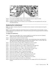
... power cords, input/output (I/O) cables, and any media (disks, CDs, or memory cards) from scratches or other damage. Refer to "Replacing the optical drive". Step 5. Refer to "Replacing a memory module". Remove the TV tuner card. Refer to the motherboard. Remove the computer cover. Remove the rear I /O module". Chapter 7. Connect the new speaker cables to "Replacing the WLAN card". Refer to "Replacing the TV tuner card". Step 9. Step 16. Remove the memory module. Step 7. Remove the heatsink. Refer to "Replacing the hard disk drive...
... power cords, input/output (I/O) cables, and any media (disks, CDs, or memory cards) from scratches or other damage. Refer to "Replacing the optical drive". Step 5. Refer to "Replacing a memory module". Remove the TV tuner card. Refer to the motherboard. Remove the computer cover. Remove the rear I /O module". Chapter 7. Connect the new speaker cables to "Replacing the WLAN card". Refer to "Replacing the TV tuner card". Step 9. Step 16. Remove the memory module. Step 7. Remove the heatsink. Refer to "Replacing the hard disk drive...
Lenovo C225\C320\C325 Hardware Maintenance Manual
Page 56
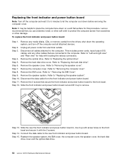
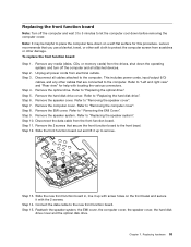
... "Replacing the speaker system". Step 7. Remove the computer cover. Step 11. Reattach the speaker system, the EMI cover, the computer cover, the speaker cover, the hard disk drive cover and the optical disk drive. 52 Lenovo C2/C3 Hardware Maintenance Manual Remove the speaker cover. Remove the EMI cover. Remove the 2 screws that are connected to the computer. Step 6. Step 13. Step 3. Refer to "Replacing the optical drive". Disconnect the data cable from electrical outlets. Slide the front indicator and power button board out...
... "Replacing the speaker system". Step 7. Remove the computer cover. Step 11. Reattach the speaker system, the EMI cover, the computer cover, the speaker cover, the hard disk drive cover and the optical disk drive. 52 Lenovo C2/C3 Hardware Maintenance Manual Remove the speaker cover. Remove the EMI cover. Remove the 2 screws that are connected to the computer. Step 6. Step 13. Step 3. Refer to "Replacing the optical drive". Disconnect the data cable from electrical outlets. Slide the front indicator and power button board out...
Lenovo C225\C320\C325 Hardware Maintenance Manual
Page 57
... 2 screws. Step 14. To replace the front function board: Step 1. Refer to remove. Step 7. Step 10. Chapter 7. Remove any other soft cloth to "Removing the speaker cover". Step 5. Remove the speaker system. Step 13. Connect the data cable to the computer. This includes power cords, input/output (I/O) cables, and any media (disks, CDs, or memory cards) from the drives, shut down the operating system, and turn off the computer and...
... 2 screws. Step 14. To replace the front function board: Step 1. Refer to remove. Step 7. Step 10. Chapter 7. Remove any other soft cloth to "Removing the speaker cover". Step 5. Remove the speaker system. Step 13. Connect the data cable to the computer. This includes power cords, input/output (I/O) cables, and any media (disks, CDs, or memory cards) from the drives, shut down the operating system, and turn off the computer and...
Lenovo C225\C320\C325 User Guide V1.0
Page 30
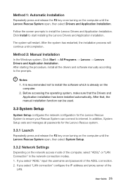
... network access mode of the LAN. Before accessing the operating system, make sure that , the manual installation function can connect to ensure your Rescue System can be used. 3.3 System Setup System Setup configures the network configuration for the Lenovo Rescue system. 3.3.1 Launch Repeatedly press and release the F2 key once turning on the computer until the Lenovo Rescue System open , then select Drivers and Application Installation. In addition, System Setup sets and manages all the drivers and software manually...
... network access mode of the LAN. Before accessing the operating system, make sure that , the manual installation function can connect to ensure your Rescue System can be used. 3.3 System Setup System Setup configures the network configuration for the Lenovo Rescue system. 3.3.1 Launch Repeatedly press and release the F2 key once turning on the computer until the Lenovo Rescue System open , then select Drivers and Application Installation. In addition, System Setup sets and manages all the drivers and software manually...
Lenovo C225\C320\C325 User Guide V1.0
Page 37
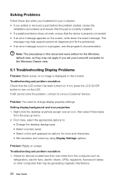
... you troubleshoot your Lenovo® computer to the Windows Classic view. 5.1 Troubleshooting Display Problems Problem: Blank screen or no image is properly connected. • If an error message appears on the screen, write down the exact message. Problem: You need to Lenovo Customer Service. Setting display background and icon properties: 1. If still cannot solve the problem, contact to change display property settings. Solving Problems Follow these tips when you added or removed a part before the problem started, review the installation...
... you troubleshoot your Lenovo® computer to the Windows Classic view. 5.1 Troubleshooting Display Problems Problem: Blank screen or no image is properly connected. • If an error message appears on the screen, write down the exact message. Problem: You need to Lenovo Customer Service. Setting display background and icon properties: 1. If still cannot solve the problem, contact to change display property settings. Solving Problems Follow these tips when you added or removed a part before the problem started, review the installation...
Lenovo C225\C320\C325 Hardware Replacement Guide V1.0
Page 6
... card installed. This guide does not include procedures for parts ordering information. Note: Use only parts provided by Lenovo®. This guide contains procedures for replacing the following parts: • Memory modules • Hard disk drive • Optical drive • Keyboard, mouse (wired) • Power cord Safety information for step-by customers who are replacing Field Replaceable Units (FRUs). If you can be replaced by trained service personnel without the need for replacing CRUs Do not open...
... card installed. This guide does not include procedures for parts ordering information. Note: Use only parts provided by Lenovo®. This guide contains procedures for replacing the following parts: • Memory modules • Hard disk drive • Optical drive • Keyboard, mouse (wired) • Power cord Safety information for step-by customers who are replacing Field Replaceable Units (FRUs). If you can be replaced by trained service personnel without the need for replacing CRUs Do not open...


