Hardware Maintenance Manual
Page 5
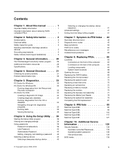
... Replacing the CMOS battery 69 Replacing the microprocessor 70 Replacing the system board 72 Replacing a hard disk drive 73 Replacing an optical drive 74 Replacing a memory module 75 Replacing the modem 76 Replacing the Express card assembly . . . . . 77 Replacing the Media Card Reader 78 Replacing the system fan assembly 79 Completing... 10. Additional Service Information 139 Security features 139 Hardware controlled Passwords 139 Operating system password 139 Vital product data 139 BIOS levels 139 © Copyright Lenovo 2005, 2010 v Contents Chapter 1.
... Replacing the CMOS battery 69 Replacing the microprocessor 70 Replacing the system board 72 Replacing a hard disk drive 73 Replacing an optical drive 74 Replacing a memory module 75 Replacing the modem 76 Replacing the Express card assembly . . . . . 77 Replacing the Media Card Reader 78 Replacing the system fan assembly 79 Completing... 10. Additional Service Information 139 Security features 139 Hardware controlled Passwords 139 Operating system password 139 Vital product data 139 BIOS levels 139 © Copyright Lenovo 2005, 2010 v Contents Chapter 1.

Hardware Maintenance Manual
Page 50
... (flashing) BIOS from a CD-ROM or diskette" on page 139 3. System board 1. See "Updating (flashing) BIOS from a CD-ROM or diskette" on page 139 2. Run memory test 4. System board 1. Press F3 to "Undetermined problems" on page 139 2. System board 1. Reboot the system 2. See "Updating (flashing) BIOS from a CD-ROM or diskette...
... (flashing) BIOS from a CD-ROM or diskette" on page 139 3. System board 1. See "Updating (flashing) BIOS from a CD-ROM or diskette" on page 139 2. Run memory test 4. System board 1. Press F3 to "Undetermined problems" on page 139 2. System board 1. Reboot the system 2. See "Updating (flashing) BIOS from a CD-ROM or diskette...

Hardware Maintenance Manual
Page 51
...) BIOS from a CD-ROM or diskette" on page 139 2. Flash the system. See "Updating (flashing) BIOS from a CD-ROM or diskette" on page 139 2. Run memory test 4. Flash the system. System board 1. System board Information only Re-start the test to reset the log file Chapter 7. Press F3 to -FRU Index...
...) BIOS from a CD-ROM or diskette" on page 139 2. Flash the system. See "Updating (flashing) BIOS from a CD-ROM or diskette" on page 139 2. Run memory test 4. Flash the system. System board 1. System board Information only Re-start the test to reset the log file Chapter 7. Press F3 to -FRU Index...

Hardware Maintenance Manual
Page 55
... is called out in warning statement 4. System board 015-000-XXX USB port Interface Test Passed No action 015-001-XXX USB port Presence 1. Run memory test 4. Remove USB device(s) and re-test 2. Flash the system. Diagnostic Error Code FRU/Action 006-197-XXX Diskette interface test warning 1. Re-run test...
... is called out in warning statement 4. System board 015-000-XXX USB port Interface Test Passed No action 015-001-XXX USB port Presence 1. Run memory test 4. Remove USB device(s) and re-test 2. Flash the system. Diagnostic Error Code FRU/Action 006-197-XXX Diskette interface test warning 1. Re-run test...

Hardware Maintenance Manual
Page 64
... Flash system 2. Diskette Drive Cable 2. Diskette drive 4. CD-ROM Drive Cable 2. Check AC/DC power adapter voltages 3. Assure Asset Security Enabled 2. Replace the memory module called out by the test 2. System board 3. Check fans 2. Reseat the hard disk drive cable 4. Hard Disk drive (IDE) 5. Flash the system ...Security Test Passed 185-XXX-XXX Asset Security failure 185-278-XXX Asset Security Chassis Intrusion 201-000-XXX System Memory Test Passed 201-XXX-XXX System Memory error 202-000-XXX System Cache Test Passed 202-XXX-XXX System Cache error 206-000-XXX Diskette Drive ...
... Flash system 2. Diskette Drive Cable 2. Diskette drive 4. CD-ROM Drive Cable 2. Check AC/DC power adapter voltages 3. Assure Asset Security Enabled 2. Replace the memory module called out by the test 2. System board 3. Check fans 2. Reseat the hard disk drive cable 4. Hard Disk drive (IDE) 5. Flash the system ...Security Test Passed 185-XXX-XXX Asset Security failure 185-278-XXX Asset Security Chassis Intrusion 201-000-XXX System Memory Test Passed 201-XXX-XXX System Memory error 202-000-XXX System Cache Test Passed 202-XXX-XXX System Cache error 206-000-XXX Diskette Drive ...
Hardware Maintenance Manual
Page 65
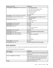
... symptoms. Beep Symptom 1, 2, or 3 beeps 4, 5, 6, or 7 beeps9, 10, or 11 beeps 8 beeps FRU/Action Reseat the memory modules. Replace the system board. Run Setup to -FRU Index 59 If the error persists, replace the memory modules one at a time until the failing adapter is determined. Chapter 7. System board No action 1. Otherwise, reinstall...
... symptoms. Beep Symptom 1, 2, or 3 beeps 4, 5, 6, or 7 beeps9, 10, or 11 beeps 8 beeps FRU/Action Reseat the memory modules. Replace the system board. Run Setup to -FRU Index 59 If the error persists, replace the memory modules one at a time until the failing adapter is determined. Chapter 7. System board No action 1. Otherwise, reinstall...
Hardware Maintenance Manual
Page 66
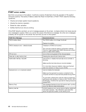
...a keyboard, set to a weak CMOS battery. Make sure the keyboard is set the error halt condition in Setup is properly connected to skip memory test HARD DISK INSTALL FAILURE Keyboard error or no longer functional. POST does the following operations. • Checks some options. Pressing Esc skips ...will not appear on the screen the next time you power-on the system, it performs a series of tests is no keyboard present Memory Test: Memory test fail Description/Action The CMOS battery is called the Power-On Self-Test, or POST. Checksum of the microprocessor. nnnn is ...
...a keyboard, set to a weak CMOS battery. Make sure the keyboard is set the error halt condition in Setup is properly connected to skip memory test HARD DISK INSTALL FAILURE Keyboard error or no longer functional. POST does the following operations. • Checks some options. Pressing Esc skips ...will not appear on the screen the next time you power-on the system, it performs a series of tests is no keyboard present Memory Test: Memory test fail Description/Action The CMOS battery is called the Power-On Self-Test, or POST. Checksum of the microprocessor. nnnn is ...
Hardware Maintenance Manual
Page 67
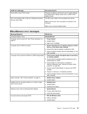
...See "Power problems" on page 31. 1. Riser card, if installed Computer will not perform a Wake On LAN® (if applicable) 1. System Board 2. Memory Module 3. System Board Chapter 7. Miscellaneous error messages Message/Symptom FRU/Action Changing display colors Display/Monitor Computer will not power-off. See "Power problems" on...remains on page 39) 4. System Board 3. Diskette Drive Cable Flashing cursor with an otherwise blank display. 1. Hard Disk Drive Cable Incorrect memory size during POST 1. Run the Memory tests 2. Symptom-to network adapter 2.
...See "Power problems" on page 31. 1. Riser card, if installed Computer will not perform a Wake On LAN® (if applicable) 1. System Board 2. Memory Module 3. System Board Chapter 7. Miscellaneous error messages Message/Symptom FRU/Action Changing display colors Display/Monitor Computer will not power-off. See "Power problems" on...remains on page 39) 4. System Board 3. Diskette Drive Cable Flashing cursor with an otherwise blank display. 1. Hard Disk Drive Cable Incorrect memory size during POST 1. Run the Memory tests 2. Symptom-to network adapter 2.

Hardware Maintenance Manual
Page 68
System Board 2. Diskette Drive Cable 3. System Board Printer problems 1. Keyboard Cable 3. System Board Undetermined problems 1. Memory modules d. Hard disk drive h. Display 2. Non-system disk or disk error-type message with a known-good diagnostic diskette. 1. System Board Power-on indicator or hard ... all keys on the keyboard do not work 1. Turn off the computer. 2. Remove or disconnect the following components (if installed) one at a time. Extended video memory e.
System Board 2. Diskette Drive Cable 3. System Board Printer problems 1. Keyboard Cable 3. System Board Undetermined problems 1. Memory modules d. Hard disk drive h. Display 2. Non-system disk or disk error-type message with a known-good diagnostic diskette. 1. System Board Power-on indicator or hard ... all keys on the keyboard do not work 1. Turn off the computer. 2. Remove or disconnect the following components (if installed) one at a time. Extended video memory e.

Hardware Maintenance Manual
Page 74
7 System board System board locations 1 Microprocessor and heat sink 2 Modem daughter card (MDC) connector 3 Battery 4 Thermal sense cable connector 5 Memory connectors (2) 6 Serial (COM) connector 7 Front panel connector 8 Front USB connector 9 SATA IDE connectors (2) Opening the cover Important 10 ExpressCard USB connector 11 ExpressCard PCIe connector ...
7 System board System board locations 1 Microprocessor and heat sink 2 Modem daughter card (MDC) connector 3 Battery 4 Thermal sense cable connector 5 Memory connectors (2) 6 Serial (COM) connector 7 Front panel connector 8 Front USB connector 9 SATA IDE connectors (2) Opening the cover Important 10 ExpressCard USB connector 11 ExpressCard PCIe connector ...

Hardware Maintenance Manual
Page 78
..." on page 68. 2. Take note of the location of the cover. 5. See "System board locations" on the system board and disconnect all cables. Remove the memory modules from the new microprocessor onto the defective microprocessor after the installation is complete. 10. Position the heat sink on the retention module so that...
..." on page 68. 2. Take note of the location of the cover. 5. See "System board locations" on the system board and disconnect all cables. Remove the memory modules from the new microprocessor onto the defective microprocessor after the installation is complete. 10. Position the heat sink on the retention module so that...

Hardware Maintenance Manual
Page 81
Replace the front bezel. 9. See "System board locations" on how to replace a memory module. 1. Chapter 8. Replacing FRUs 75 Connect the signal and power cables to "Completing the FRU replacement" on page 81. Open the computer cover. Slide the ... into the drive bay until it on page 68. 2. Go to the drive. 8. Replacing a memory module This section provides instructions on page 68. 3. Locate the memory connector. See "Opening the cover" on the new optical drive. 6. Remove the memory module being replaced by opening the retaining clips as shown. Remove the retainer bracket...
Replace the front bezel. 9. See "System board locations" on how to replace a memory module. 1. Chapter 8. Replacing FRUs 75 Connect the signal and power cables to "Completing the FRU replacement" on page 81. Open the computer cover. Slide the ... into the drive bay until it on page 68. 2. Go to the drive. 8. Replacing a memory module This section provides instructions on page 68. 3. Locate the memory connector. See "Opening the cover" on the new optical drive. 6. Remove the memory module being replaced by opening the retaining clips as shown. Remove the retainer bracket...

Hardware Maintenance Manual
Page 82
... firmly fixed in the connector and does not move easily. 5. Go to the MDC connector. 76 Hardware Maintenance Manual Press the memory module firmly, and pivot the memory module until it snaps into the socket 1 . Locate the MDC connector. The modem card 1 will be connected to "Completing ...the FRU replacement" on how to replace the modem. 1. Insert the notched end 2 of the memory module into place. Replacing the modem This...
... firmly fixed in the connector and does not move easily. 5. Go to the MDC connector. 76 Hardware Maintenance Manual Press the memory module firmly, and pivot the memory module until it snaps into the socket 1 . Locate the MDC connector. The modem card 1 will be connected to "Completing ...the FRU replacement" on how to replace the modem. 1. Insert the notched end 2 of the memory module into place. Replacing the modem This...
Hardware Maintenance Manual
Page 90
... FSB, 1MB L2 (models 16Q 17S 17Y) 9 Heat sink Intel (all models) 10 Kit, Shell (all models) 11 Memory module, 512MB DDR2 PC2-5300 (667MHz) SoDIMM (models 12Q 14C 14V 17S 17Y) 11 Memory module, 1GB DDR2 PC2-5300 (667MHz) SoDIMM (models 11S 11D 11Y 13B 13H 15S 15D 15Y 15Q 15C... 16Q 18S 18Y) 11 Memory module, 2GB DDR2 PC2-5300 (667MHz) SoDIMM (models) 12 Internal speaker (all models) 13 Media card reader (all models) 4 DVD-ROM Drive - 16x/48x - Item # ...
... FSB, 1MB L2 (models 16Q 17S 17Y) 9 Heat sink Intel (all models) 10 Kit, Shell (all models) 11 Memory module, 512MB DDR2 PC2-5300 (667MHz) SoDIMM (models 12Q 14C 14V 17S 17Y) 11 Memory module, 1GB DDR2 PC2-5300 (667MHz) SoDIMM (models 11S 11D 11Y 13B 13H 15S 15D 15Y 15Q 15C... 16Q 18S 18Y) 11 Memory module, 2GB DDR2 PC2-5300 (667MHz) SoDIMM (models) 12 Internal speaker (all models) 13 Media card reader (all models) 4 DVD-ROM Drive - 16x/48x - Item # ...

Hardware Maintenance Manual
Page 100
..., E2200, 2.20GHz, 800MHz FSB, 1MB L2 (models) 9 Heat sink Intel (models) 10 Kit, shell (models) 11 Memory module, 512MB DDR2 PC2-5300 (667MHz) SoDIMM (models) 11 Memory module, 1GB DDR2 PC2-5300 (667MHz) SoDIMM (models) 11 Memory module, 2GB DDR2 PC2-5300 (667MHz) SoDIMM (models) 12 Internal speaker (models) 13 Media card reader...
..., E2200, 2.20GHz, 800MHz FSB, 1MB L2 (models) 9 Heat sink Intel (models) 10 Kit, shell (models) 11 Memory module, 512MB DDR2 PC2-5300 (667MHz) SoDIMM (models) 11 Memory module, 1GB DDR2 PC2-5300 (667MHz) SoDIMM (models) 11 Memory module, 2GB DDR2 PC2-5300 (667MHz) SoDIMM (models) 12 Internal speaker (models) 13 Media card reader...

Hardware Maintenance Manual
Page 112
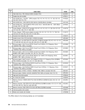
... 67J 68S 68Y 68G 68M 68A 68T 68K 68J 84U 84F 84M 84A 84Q 84T 84K 84J 85U 85F) 9 Heat sink Intel (all models) 11 Memory module, 512MB DDR2 PC2-5300 (667MHz) SoDIMM (models 1S 11D 11Y 11A 11T 12S ) FRU# 46R3848 45C6898 45C6899 45C6900 45C6901 45C6902 45C8499 45C8531 46R4261 46R4260...
... 67J 68S 68Y 68G 68M 68A 68T 68K 68J 84U 84F 84M 84A 84Q 84T 84K 84J 85U 85F) 9 Heat sink Intel (all models) 11 Memory module, 512MB DDR2 PC2-5300 (667MHz) SoDIMM (models 1S 11D 11Y 11A 11T 12S ) FRU# 46R3848 45C6898 45C6899 45C6900 45C6901 45C6902 45C8499 45C8531 46R4261 46R4260...

Hardware Maintenance Manual
Page 113
Item # 6395 FRUs 11 Memory module, 1GB DDR2 PC2-5300 (667MHz) SoDIMM (models 12S 12D 12Y 12G 13S 13G 13C 13B 13H 14S 14D 14Y 14M 14A 14T 14K 14J ... 41J 42M 42A 42J 43M 43A 43Q 43T 43K 43J 44A 44Q 44T 46M 46A 46Q 46T 46K 46J 33M 34M 61U 61F 61S) 11 Memory module, 2GB DDR2 PC2-5300 (667MHz) SoDIMM (models 27U 27F 28U 28F 29U 29F 29S 29L 29D 29Y 29G 29M 29A 29Q 29T 29C 29B...
Item # 6395 FRUs 11 Memory module, 1GB DDR2 PC2-5300 (667MHz) SoDIMM (models 12S 12D 12Y 12G 13S 13G 13C 13B 13H 14S 14D 14Y 14M 14A 14T 14K 14J ... 41J 42M 42A 42J 43M 43A 43Q 43T 43K 43J 44A 44Q 44T 46M 46A 46Q 46T 46K 46J 33M 34M 61U 61F 61S) 11 Memory module, 2GB DDR2 PC2-5300 (667MHz) SoDIMM (models 27U 27F 28U 28F 29U 29F 29S 29L 29D 29Y 29G 29M 29A 29Q 29T 29C 29B...

Hardware Maintenance Manual
Page 124
..., 3MB L2 (models) 8 Microprocessor, E2200, 2.20GHz, 800MHz FSB, 1MB L2 (models) 9 Heat sink Intel (models) 11 Memory module, 512MB DDR2 PC2-5300 (667MHz) SoDIMM (models) 11 Memory module, 1GB DDR2 PC2-5300 (667MHz) SoDIMM (models) 11 Memory module, 2GB DDR2 PC2-5300 (667MHz) SoDIMM (models) 12 Internal speaker (models) 13 Media card reader...
..., 3MB L2 (models) 8 Microprocessor, E2200, 2.20GHz, 800MHz FSB, 1MB L2 (models) 9 Heat sink Intel (models) 11 Memory module, 512MB DDR2 PC2-5300 (667MHz) SoDIMM (models) 11 Memory module, 1GB DDR2 PC2-5300 (667MHz) SoDIMM (models) 11 Memory module, 2GB DDR2 PC2-5300 (667MHz) SoDIMM (models) 12 Internal speaker (models) 13 Media card reader...
Hardware Maintenance Manual
Page 134
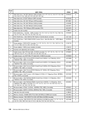
...8 Microprocessor, E7200, 2.53GHz, 1066MHz FSB, 3MB L2 (models) 8 Microprocessor, E2200, 2.20GHz, 800MHz FSB, 1MB L2 (models) 9 Heat sink Intel (all models) 11 Memory module, 512MB DDR2 PC2-5300 (667MHz) SoDIMM (all models) 4 DVD-ROM Drive - 16x/48x - Item # 6397 FRUs 2 Hard disk drive, 160 GB 7200rpm SATA (models...GB 7200rpm SATA (models) 2 Hard disk drive, 1TB 7200rpm SATA (models CTO) 3 System fan (all models) 11 Memory module, 1GB DDR2 PC2-5300 (667MHz) SoDIMM (models) 11 Memory module, 2GB DDR2 PC2-5300 (667MHz) SoDIMM (models 11U 11F 11S 11L 11D 11Y 11G 11M 11A 11Q 11T 11C 11B...
...8 Microprocessor, E7200, 2.53GHz, 1066MHz FSB, 3MB L2 (models) 8 Microprocessor, E2200, 2.20GHz, 800MHz FSB, 1MB L2 (models) 9 Heat sink Intel (all models) 11 Memory module, 512MB DDR2 PC2-5300 (667MHz) SoDIMM (all models) 4 DVD-ROM Drive - 16x/48x - Item # 6397 FRUs 2 Hard disk drive, 160 GB 7200rpm SATA (models...GB 7200rpm SATA (models) 2 Hard disk drive, 1TB 7200rpm SATA (models CTO) 3 System fan (all models) 11 Memory module, 1GB DDR2 PC2-5300 (667MHz) SoDIMM (models) 11 Memory module, 2GB DDR2 PC2-5300 (667MHz) SoDIMM (models 11U 11F 11S 11L 11D 11Y 11G 11M 11A 11Q 11T 11C 11B...

Hardware Maintenance Manual
Page 145
... web site: http://www.lenovo.com/support/ 2. Lenovo Customer Support Center 3. Updating (flashing) BIOS from a CD-ROM or diskette This section describes how to the computer by the computer. Security features Security features in the nonvolatile memory on password and denies access to update (flash) the BIOS using the Setup Utility program. After...
... web site: http://www.lenovo.com/support/ 2. Lenovo Customer Support Center 3. Updating (flashing) BIOS from a CD-ROM or diskette This section describes how to the computer by the computer. Security features Security features in the nonvolatile memory on password and denies access to update (flash) the BIOS using the Setup Utility program. After...


