Hardware Maintenance Manual
Page 5
... card assembly . . . . . 77 Replacing the Media Card Reader 78 Replacing the system fan assembly 79 Completing the FRU replacement 81 Chapter 9. About this manual . . . . . 1 Important Safety Information 1 Important information about replacing RoHS compliant FRUs 1 Chapter 2. Additional Service Information 139 Security features 139 Hardware controlled Passwords 139 Operating system password 139 Vital product data 139 BIOS levels 139 © Copyright Lenovo 2005, 2010 v Symptom-to-FRU Index . 43 Hard disk drive boot error 43 Diagnostic error codes...
... card assembly . . . . . 77 Replacing the Media Card Reader 78 Replacing the system fan assembly 79 Completing the FRU replacement 81 Chapter 9. About this manual . . . . . 1 Important Safety Information 1 Important information about replacing RoHS compliant FRUs 1 Chapter 2. Additional Service Information 139 Security features 139 Hardware controlled Passwords 139 Operating system password 139 Vital product data 139 BIOS levels 139 © Copyright Lenovo 2005, 2010 v Symptom-to-FRU Index . 43 Hard disk drive boot error 43 Diagnostic error codes...
Hardware Maintenance Manual
Page 35
... have Internet access, the most ThinkCentre products. You can find the following information: • Customer Replaceable Unit (CRU) removal and installation instructions • Publications • Troubleshooting information • Parts information • Downloads and drivers • Links to help solve problems and get repair service or other useful sources of the computer. Specifications This section lists the physical specifications for general information about the use, operation, and maintenance of information To access this...
... have Internet access, the most ThinkCentre products. You can find the following information: • Customer Replaceable Unit (CRU) removal and installation instructions • Publications • Troubleshooting information • Parts information • Downloads and drivers • Links to help solve problems and get repair service or other useful sources of the computer. Specifications This section lists the physical specifications for general information about the use, operation, and maintenance of information To access this...
Hardware Maintenance Manual
Page 37
... the instructions: • If you did not receive the correct response, proceed to help troubleshoot. 1. Press the power switch to turn on the display. Check the power indicator LED next to the information supplied with that the power cord is installed on ), the computer power is found by an application program, the operating system, or both. Verify that software package. General error messages appear if a problem...
... the instructions: • If you did not receive the correct response, proceed to help troubleshoot. 1. Press the power switch to turn on the display. Check the power indicator LED next to the information supplied with that the power cord is installed on ), the computer power is found by an application program, the operating system, or both. Verify that software package. General error messages appear if a problem...
Hardware Maintenance Manual
Page 38
... configuration options set -up between "working and non-working , what changes were made prior to assist you in the same locations 4. Have the same setup for the operating system control files Comparing the configuration and software set in the system 8. See "Opening the cover" on page 66. 8. Check the Power switch/LED assembly connector on page 72. Reseat the cable from Service Support and Engineering functions. • Machine type and model • Processor or hard disk upgrades • Failure symptom - Replace...
... configuration options set -up between "working and non-working , what changes were made prior to assist you in the same locations 4. Have the same setup for the operating system control files Comparing the configuration and software set in the system 8. See "Opening the cover" on page 66. 8. Check the Power switch/LED assembly connector on page 72. Reseat the cable from Service Support and Engineering functions. • Machine type and model • Processor or hard disk upgrades • Failure symptom - Replace...
Hardware Maintenance Manual
Page 39
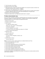
... unable to a Lenovo technical support representative. To run diagnostics from the Windows desktop, select All Programs, select PC-Doctor for Windows, and click PC-Doctor for computer problems, access the Lenovo troubleshooting center, update system drivers, and review system information. Shut down the operating system and turn on the screen. Select the diagnostic test you speak to start ) Notes: 1. You will not start the Windows operating system or if PC-Doctor for Windows PE diagnostic program from...
... unable to a Lenovo technical support representative. To run diagnostics from the Windows desktop, select All Programs, select PC-Doctor for Windows, and click PC-Doctor for computer problems, access the Lenovo troubleshooting center, update system drivers, and review system information. Shut down the operating system and turn on the screen. Select the diagnostic test you speak to start ) Notes: 1. You will not start the Windows operating system or if PC-Doctor for Windows PE diagnostic program from...

Hardware Maintenance Manual
Page 41
.... • Press F5 to select a menu item. • The Esc key is marked by >>. Run Normal Test runs a more tests, use the following error code format: Function Code Failure Type DeviceID Date ChkDigits Text Chapter 5. Press Esc at any time to run the diagnostic tests. • Using the cursor movement keys, highlight Run Normal Test or Run Quick Test from the drive. 7. When the diagnostics program opens, follow the instructions on page 36. When the...
.... • Press F5 to select a menu item. • The Esc key is marked by >>. Run Normal Test runs a more tests, use the following error code format: Function Code Failure Type DeviceID Date ChkDigits Text Chapter 5. Press Esc at any time to run the diagnostic tests. • Using the cursor movement keys, highlight Run Normal Test or Run Quick Test from the drive. 7. When the diagnostics program opens, follow the instructions on page 36. When the...

Hardware Maintenance Manual
Page 42
... Full Erase Hard Drive provides a DOS utility that performs the following : • Destroys the Master Boot Record (MBR) on the hard drive. • Destroys all copies of the FAT Table on the PCI bus. • Date: Contains the date when the diagnostic test was run. Select the UTILITY option on the specified date. - Select either a fixed disk drive, removable media drive, processor, specific RIMM, or a device on all partitions (both the...
... Full Erase Hard Drive provides a DOS utility that performs the following : • Destroys the Master Boot Record (MBR) on the hard drive. • Destroys all copies of the FAT Table on the PCI bus. • Date: Contains the date when the diagnostic test was run. Select the UTILITY option on the specified date. - Select either a fixed disk drive, removable media drive, processor, specific RIMM, or a device on all partitions (both the...

Hardware Maintenance Manual
Page 46
... set, the computer cannot be any boot device. Select Set Passwords. After you try to change the startup sequence. 40 Hardware Maintenance Manual Start the Setup Utility program (see "Password considerations" on the computer. 3. Turn off the computer. 2. Note: Not all CDs, hard disks, and diskettes are responsible for maintaining the settings of the screen. Note: If you are bootable. 1. Note: Selecting a startup device from the keyboard. • Setup Utility program and hard disk drive passwords are not case...
... set, the computer cannot be any boot device. Select Set Passwords. After you try to change the startup sequence. 40 Hardware Maintenance Manual Start the Setup Utility program (see "Password considerations" on the computer. 3. Turn off the computer. 2. Note: Not all CDs, hard disks, and diskettes are responsible for maintaining the settings of the screen. Note: If you are bootable. 1. Note: Selecting a startup device from the keyboard. • Setup Utility program and hard disk drive passwords are not case...

Hardware Maintenance Manual
Page 52
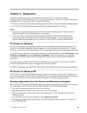
... page 62 1. Device on IRQ10 2. System board 1. System board 1. Device on IRQ7 2. Go to "Undetermined problems" on page 62 2. Device on IRQ9 2. System board 1. Flash the system and re-test 3. System board 1. Diskette drive 3. See "Updating (flashing) BIOS from a CD-ROM or diskette" on IRQ8 2. System board 1. Device on page 139 3. System board 46 Hardware Maintenance Manual Replace the component that is called out, make sure it is connected and/or enabled. Diskette Cable 2. Diagnostic Error Code 001-197...
... page 62 1. Device on IRQ10 2. System board 1. System board 1. Device on IRQ7 2. Go to "Undetermined problems" on page 62 2. Device on IRQ9 2. System board 1. Flash the system and re-test 3. System board 1. Diskette drive 3. See "Updating (flashing) BIOS from a CD-ROM or diskette" on IRQ8 2. System board 1. Device on page 139 3. System board 46 Hardware Maintenance Manual Replace the component that is called out, make sure it is connected and/or enabled. Diskette Cable 2. Diagnostic Error Code 001-197...

Hardware Maintenance Manual
Page 55
... reset the log file Chapter 7. System board 015-015-XXX USB port External Loopback failure 1. See "Updating (flashing) BIOS from a CD-ROM or diskette" on page 139 3. Remove USB device(s) and re-test 2. See "Updating (flashing) BIOS from a CD-ROM or diskette" on page 139 2. Replace the component that is called out, make sure it is connected and/or enabled 2. Remove USB device(s) and re-test 2. Remove USB device(s) and re-test 2. Run memory test 4. Go to review the log file 2. Diskette drive cable 2. Remove USB device(s) and re-test 2. Flash...
... reset the log file Chapter 7. System board 015-015-XXX USB port External Loopback failure 1. See "Updating (flashing) BIOS from a CD-ROM or diskette" on page 139 3. Remove USB device(s) and re-test 2. See "Updating (flashing) BIOS from a CD-ROM or diskette" on page 139 2. Replace the component that is called out, make sure it is connected and/or enabled 2. Remove USB device(s) and re-test 2. Remove USB device(s) and re-test 2. Run memory test 4. Go to review the log file 2. Diskette drive cable 2. Remove USB device(s) and re-test 2. Flash...

Hardware Maintenance Manual
Page 57
... 1. Check power supply voltages 3. Flash the system. See "Updating (flashing) BIOS from a CD-ROM or diskette" on page 39 2. Reseat IDE signal cable 4. IDE signal cable 2. Riser card, if installed 3. See Chapter 6 "Diagnostics, Test and Recovery Information" on page 62 2. PCI card 2. System board No action 1. Replace component under test 1. IDE device 5. System board Information only Re-start the test to review the log file 2. Diagnostic Error Code 018-250-XXX PCI Card Services error 020-000-XXX PCI Interface Test Passed 020...
... 1. Check power supply voltages 3. Flash the system. See "Updating (flashing) BIOS from a CD-ROM or diskette" on page 39 2. Reseat IDE signal cable 4. IDE signal cable 2. Riser card, if installed 3. See Chapter 6 "Diagnostics, Test and Recovery Information" on page 62 2. PCI card 2. System board No action 1. Replace component under test 1. IDE device 5. System board Information only Re-start the test to review the log file 2. Diagnostic Error Code 018-250-XXX PCI Card Services error 020-000-XXX PCI Interface Test Passed 020...

Hardware Maintenance Manual
Page 58
... power adapter 3. System board 52 Hardware Maintenance Manual SCSI adapter card, if installed 5. SCSI signal cable 2. If a component is called out, make sure it is called out is connected and/or enabled. SCSI device 4. SCSI device 4. Make sure the component that is connected and/or enabled. SCSI adapter card, if installed 5. System board Information only Re-start the test to "Undetermined problems" on page 39 2. Press F3 to "Undetermined problems" on page 139 3. See "Updating (flashing) BIOS from a CD-ROM...
... power adapter 3. System board 52 Hardware Maintenance Manual SCSI adapter card, if installed 5. SCSI signal cable 2. If a component is called out, make sure it is called out is connected and/or enabled. SCSI device 4. SCSI device 4. Make sure the component that is connected and/or enabled. SCSI adapter card, if installed 5. System board Information only Re-start the test to "Undetermined problems" on page 39 2. Press F3 to "Undetermined problems" on page 139 3. See "Updating (flashing) BIOS from a CD-ROM...

Hardware Maintenance Manual
Page 64
See "Undetermined problems" on page 139 3. Flash the system and re-test. Replace the memory module called out by the test 2. Cache, if removable 2. CD-ROM Drive Cable 2. System board No action 1. Check AC/DC power adapter voltages 3. System board 58 Hardware Maintenance Manual See "Updating (flashing) BIOS from a CD-ROM or diskette" on page 62 2. Microprocessor 4. C2 Cover Switch 3. System board No action 1. Check AC/DC power adapter voltages 3. Hard Disk drive (IDE) 5. Diagnostic Error Code 175-199-XXX Thermal Sensor(s) test failed...
See "Undetermined problems" on page 139 3. Flash the system and re-test. Replace the memory module called out by the test 2. Cache, if removable 2. CD-ROM Drive Cable 2. System board No action 1. Check AC/DC power adapter voltages 3. System board 58 Hardware Maintenance Manual See "Updating (flashing) BIOS from a CD-ROM or diskette" on page 62 2. Microprocessor 4. C2 Cover Switch 3. System board No action 1. Check AC/DC power adapter voltages 3. Hard Disk drive (IDE) 5. Diagnostic Error Code 175-199-XXX Thermal Sensor(s) test failed...
Hardware Maintenance Manual
Page 65
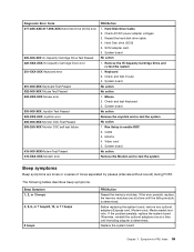
... Beep symptoms are tones or a series of tones separated by pauses (intervals without sound) during POST. Chapter 7. Hard Disk drive (SCSI) 5. Replace the system board. Reseat the hard disk drive cable 4. System board No action Remove the Joystick and re-test the system No action 1. If the problem persists, replace the system board. Check and test mouse 3. Check and test Keyboard 3. Monitor 4. Video card 5. Before replacing the system board, remove any optional adapters (Express card, Modem card, Media reader) and retry. Check AC/DC power adapter...
... Beep symptoms are tones or a series of tones separated by pauses (intervals without sound) during POST. Chapter 7. Hard Disk drive (SCSI) 5. Replace the system board. Reseat the hard disk drive cable 4. System board No action Remove the Joystick and re-test the system No action 1. If the problem persists, replace the system board. Check and test mouse 3. Check and test Keyboard 3. Monitor 4. Video card 5. Before replacing the system board, remove any optional adapters (Express card, Modem card, Media reader) and retry. Check AC/DC power adapter...
Hardware Maintenance Manual
Page 66
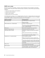
... CMOS battery. The computer loads the default configuration settings. This message displays during POST. When you correct the cause of tests is called the Power-On Self-Test, or POST. nnnn is the running speed of the memory error. 60 Hardware Maintenance Manual POST does the following operations. • Checks some options. Make sure the keyboard is properly connected to the computer and that no keys are installed, make sure the hard disk drive selection in Setup to...
... CMOS battery. The computer loads the default configuration settings. This message displays during POST. When you correct the cause of tests is called the Power-On Self-Test, or POST. nnnn is the running speed of the memory error. 60 Hardware Maintenance Manual POST does the following operations. • Checks some options. Make sure the keyboard is properly connected to the computer and that no keys are installed, make sure the hard disk drive selection in Setup to...
Hardware Maintenance Manual
Page 67
See "Power problems" on page 31. 1. Power Switch 2. Ensure that network adapter is enabled in Setup/Configuration (see "Starting the Setup Utility program" on page 39) 4. Ensure no interrupt or I/O address conflicts 6. See "Power problems" on page 31. 1. AC/DC Power Adapter 2. Diskette Drive 2. Hard Disk Drive Cable Incorrect memory size during POST 1. Symptom-to network adapter 2. Ensure Wake On LAN feature is enabled for PXE 3. System Board Chapter 7. Make sure you have bootable media. Check power supply and signal cable connections to -FRU Index...
See "Power problems" on page 31. 1. Power Switch 2. Ensure that network adapter is enabled in Setup/Configuration (see "Starting the Setup Utility program" on page 39) 4. Ensure no interrupt or I/O address conflicts 6. See "Power problems" on page 31. 1. AC/DC Power Adapter 2. Diskette Drive 2. Hard Disk Drive Cable Incorrect memory size during POST 1. Symptom-to network adapter 2. Ensure Wake On LAN feature is enabled for PXE 3. System Board Chapter 7. Make sure you have bootable media. Check power supply and signal cable connections to -FRU Index...

Hardware Maintenance Manual
Page 68
... (if installed) one at a time. Extended video memory e. Hard disk drive h. Video adapter (if present) 3. Run Setup and check Startup sequence. 2. Check the network adapter LED status Some or all keys on page 31. Keyboard Cable 3. External devices (modem, printer, or mouse) b. Non-system disk or disk error-type message with a known-good diagnostics diskette in the first 3.5-inch diskette drive 1. Power switch/LED assembly but computer works correctly 2. Diskette Drive Cable 4. Keyboard 2. Diskette drive 3. Diskette Drive Cable Other display symptoms not listed...
... (if installed) one at a time. Extended video memory e. Hard disk drive h. Video adapter (if present) 3. Run Setup and check Startup sequence. 2. Check the network adapter LED status Some or all keys on page 31. Keyboard Cable 3. External devices (modem, printer, or mouse) b. Non-system disk or disk error-type message with a known-good diagnostics diskette in the first 3.5-inch diskette drive 1. Power switch/LED assembly but computer works correctly 2. Diskette Drive Cable 4. Keyboard 2. Diskette drive 3. Diskette Drive Cable Other display symptoms not listed...

Hardware Maintenance Manual
Page 79
... pins on page 68. 2. See "Opening the cover" on the bracket with the mounting studs. 9. Open the computer cover. Position the new system board in the User Guide. Disconnect the power cable from the chassis. 5. 6. Replacing FRUs 73 Disconnect the signal and power cables from the failing system board and install it free of the hard disk drive and push upward. If the system board has a modem daughter card installed, remove it from the hard disk drive...
... pins on page 68. 2. See "Opening the cover" on the bracket with the mounting studs. 9. Open the computer cover. Position the new system board in the User Guide. Disconnect the power cable from the chassis. 5. 6. Replacing FRUs 73 Disconnect the signal and power cables from the failing system board and install it free of the hard disk drive and push upward. If the system board has a modem daughter card installed, remove it from the hard disk drive...

Hardware Maintenance Manual
Page 145
... (MIF) Hardware controlled Passwords Hardware controlled passwords are available athttp://www.lenovo.com/support on page 39. Lenovo support web site: http://www.lenovo.com/support/ 2. BIOS levels An incorrect level of BIOS: - Lenovo Customer Support Center 3. system program updates are set using a CD-ROM or diskette. Security features Security features in the computer, the latest BIOS available for obtaining the latest level BIOS available 1. Start the Setup Utility. - Select System Information on the Main setup screen. •...
... (MIF) Hardware controlled Passwords Hardware controlled passwords are available athttp://www.lenovo.com/support on page 39. Lenovo support web site: http://www.lenovo.com/support/ 2. BIOS levels An incorrect level of BIOS: - Lenovo Customer Support Center 3. system program updates are set using a CD-ROM or diskette. Security features Security features in the computer, the latest BIOS available for obtaining the latest level BIOS available 1. Start the Setup Utility. - Select System Information on the Main setup screen. •...

Hardware Maintenance Manual
Page 146
... cover and reconnect any attached devices, such as the system power supply, processor, hard disk drives, and some monitors. 140 Hardware Maintenance Manual If this time, you are prompted to the Clear CMOS/Recovery jumper. 5. During this occurs, perform the following procedure commonly called Boot-block Recovery. • If using a diskette, make sure the computer is completed, the series of beeps ends. Insert the system program update (flash) CD-ROM into the optical drive. Type the seven-character machine type/model...
... cover and reconnect any attached devices, such as the system power supply, processor, hard disk drives, and some monitors. 140 Hardware Maintenance Manual If this time, you are prompted to the Clear CMOS/Recovery jumper. 5. During this occurs, perform the following procedure commonly called Boot-block Recovery. • If using a diskette, make sure the computer is completed, the series of beeps ends. Insert the system program update (flash) CD-ROM into the optical drive. Type the seven-character machine type/model...


