
Hardware Installation Guide
Page 5
... the parts replacement 47 Obtaining device drivers 48 Chapter 5. Notices 53 Television output notice 54 Trademarks 54 Index 55 © Copyright Lenovo 2008 iii Overview 3 Additional information resources 3 Handling static-sensitive devices 4 Locations 5 Locating controls and connectors on the front of ...11 Removing the cover 11 Removing and replacing the front bezel . . . . . 13 Installing internal options 14 Installing a memory module 14 Installing an adapter card 16 Installing internal drives 18 Replacing the battery 22 Replacing the power supply 23 Replacing the ...
... the parts replacement 47 Obtaining device drivers 48 Chapter 5. Notices 53 Television output notice 54 Trademarks 54 Index 55 © Copyright Lenovo 2008 iii Overview 3 Additional information resources 3 Handling static-sensitive devices 4 Locations 5 Locating controls and connectors on the front of ...11 Removing the cover 11 Removing and replacing the front bezel . . . . . 13 Installing internal options 14 Installing a memory module 14 Installing an adapter card 16 Installing internal drives 18 Replacing the battery 22 Replacing the power supply 23 Replacing the ...

Hardware Installation Guide
Page 7
...Removing the front fan assembly . . . . . 39 36. Removing the internal speaker 43 40. Installing a padlock 50 © Copyright Lenovo 2008 v Removing the computer cover 12 6. Opening the retaining clips 14 8. Opening the adapter latch 16 10. Installing a new battery 23...12. Installing the secondary hard disk drive into bracket 28 23. Retainer bracket for diskette drive . . . . . 34 31. Installing the memory module 36 33. Controls and connectors 5 2. Rear connector locations 6 3. Installing a retainer bracket 21 14. Component locations 8 4. Removing the ...
...Removing the front fan assembly . . . . . 39 36. Removing the internal speaker 43 40. Installing a padlock 50 © Copyright Lenovo 2008 v Removing the computer cover 12 6. Opening the retaining clips 14 8. Opening the adapter latch 16 10. Installing a new battery 23...12. Installing the secondary hard disk drive into bracket 28 23. Retainer bracket for diskette drive . . . . . 34 31. Installing the memory module 36 33. Controls and connectors 5 2. Rear connector locations 6 3. Installing a retainer bracket 21 14. Component locations 8 4. Removing the ...
Hardware Installation Guide
Page 11
...removal and installation videos v Publications v Troubleshooting information v Parts information v Downloads and drivers v Links to -date information for step-by Lenovo. This guide contains instructions for installing or replacing the following parts: v Battery v Power supply v Heat sink and fan assembly v Primary... hard disk drive v Secondary hard disk drive v Optical drive v Diskette drive v Memory module v Adapter card v Front fan assembly v Rear fan assembly v Internal speaker v Keyboard v Mouse Additional information resources If you have...
...removal and installation videos v Publications v Troubleshooting information v Parts information v Downloads and drivers v Links to -date information for step-by Lenovo. This guide contains instructions for installing or replacing the following parts: v Battery v Power supply v Heat sink and fan assembly v Primary... hard disk drive v Secondary hard disk drive v Optical drive v Diskette drive v Memory module v Adapter card v Front fan assembly v Rear fan assembly v Internal speaker v Keyboard v Mouse Additional information resources If you have...

Hardware Installation Guide
Page 12
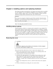
... and your movement. Never touch any exposed circuitry. v Do not place the part on the computer cover or other computer components carefully. Handle adapter cards, memory modules, system boards, and microprocessors by the edges. v Prevent others from touching the parts and other computer components, take these precautions to install the new...
... and your movement. Never touch any exposed circuitry. v Do not place the part on the computer cover or other computer components carefully. Handle adapter cards, memory modules, system boards, and microprocessors by the edges. v Prevent others from touching the parts and other computer components, take these precautions to install the new...

Hardware Installation Guide
Page 16
Figure 3. Component locations 1 Microprocessor, heat sink, and 6 heat sink fan assembly 2 Memory slots (4) 7 3 PCI Express x1 adapter card 8 slot 4 Adapter card 9 5 Adapter card slot PCI Express x16 graphics adapter card slot Cover presence (Intrusion) switch Rear system fan Power supply 8 Hardware Installation and Replacement Guide Figure 3 shows the location of the various components in your computer. Locating components To remove the computer cover, see "Removing the cover" on page 11.
Figure 3. Component locations 1 Microprocessor, heat sink, and 6 heat sink fan assembly 2 Memory slots (4) 7 3 PCI Express x1 adapter card 8 slot 4 Adapter card 9 5 Adapter card slot PCI Express x16 graphics adapter card slot Cover presence (Intrusion) switch Rear system fan Power supply 8 Hardware Installation and Replacement Guide Figure 3 shows the location of the various components in your computer. Locating components To remove the computer cover, see "Removing the cover" on page 11.

Hardware Installation Guide
Page 17
Figure 4. System board parts locations 1 Microprocessor 2 Microprocessor fan connector 3 Memory slot 1 4 Memory slot 2 5 Memory slot 3 6 Memory slot 4 7 24-pin power connector 8 Thermal sensor connector 9 Diskette drive connector 10 SATA connectors (3) 11 Parallel (LPT) connector 12 Power fan connector 13 eSATA connector ...
Figure 4. System board parts locations 1 Microprocessor 2 Microprocessor fan connector 3 Memory slot 1 4 Memory slot 2 5 Memory slot 3 6 Memory slot 4 7 24-pin power connector 8 Thermal sensor connector 9 Diskette drive connector 10 SATA connectors (3) 11 Parallel (LPT) connector 12 Power fan connector 13 eSATA connector ...
Hardware Installation Guide
Page 19
...drives, shut down your computer" on how to the computer. Disconnect the cables attached to : http://www.lenovo.com/support Note: Use only parts provided by adding memory modules, adapter cards, or drives. You can be connected to identify the required connector, and then use ...these instructions along with your computer by Lenovo. This section provides instructions on page 6. 4. Remove any repair before removing...
...drives, shut down your computer" on how to the computer. Disconnect the cables attached to : http://www.lenovo.com/support Note: Use only parts provided by adding memory modules, adapter cards, or drives. You can be connected to identify the required connector, and then use ...these instructions along with your computer by Lenovo. This section provides instructions on page 6. 4. Remove any repair before removing...

Hardware Installation Guide
Page 22
..., use the following guidelines: v Use 1.8 V, 240-pin DDR3 SDRAM (double data rate 3 synchronous dynamic random access memory). Locate the memory slots. Opening the retaining clips 14 Hardware Installation and Replacement Guide Installing internal options Important Read "Handling static-sensitive devices" on ... cover" on page 4 before removing the computer cover. See "Identifying parts on the system board" on its side. 2. v Use 1.0 GB or 2.0 GB memory modules in any combination up to a maximum of 8.0 GB of 8.0 GB. Figure 7. Note: For this procedure, it helps to a maximum of system...
..., use the following guidelines: v Use 1.8 V, 240-pin DDR3 SDRAM (double data rate 3 synchronous dynamic random access memory). Locate the memory slots. Opening the retaining clips 14 Hardware Installation and Replacement Guide Installing internal options Important Read "Handling static-sensitive devices" on ... cover" on page 4 before removing the computer cover. See "Identifying parts on the system board" on its side. 2. v Use 1.0 GB or 2.0 GB memory modules in any combination up to a maximum of 8.0 GB of 8.0 GB. Figure 7. Note: For this procedure, it helps to a maximum of system...

Hardware Installation Guide
Page 23
Push the memory module straight down into the slot until the retaining clips close. Installing the memory module 5. Go to Chapter 4, "Completing the parts replacement," on the system board. Make sure the notch 1 on the memory module aligns correctly with the slot key 2 on page 47. Installing options and replacing hardware 15 Chapter 3. 4. Position the new memory module over the memory slot. Figure 8.
Push the memory module straight down into the slot until the retaining clips close. Installing the memory module 5. Go to Chapter 4, "Completing the parts replacement," on the system board. Make sure the notch 1 on the memory module aligns correctly with the slot key 2 on page 47. Installing options and replacing hardware 15 Chapter 3. 4. Position the new memory module over the memory slot. Figure 8.
Hardware Installation Guide
Page 30
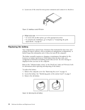
... computer cover. v To complete the installation, go to Chapter 4, "Completing the parts replacement," on the computer. Replacing the battery Your computer has a special type of memory that maintains the date, time, and settings for built-in the ThinkCentre Safety and Warranty Guide for information about replacing and disposing of the extra...
... computer cover. v To complete the installation, go to Chapter 4, "Completing the parts replacement," on the computer. Replacing the battery Your computer has a special type of memory that maintains the date, time, and settings for built-in the ThinkCentre Safety and Warranty Guide for information about replacing and disposing of the extra...

Hardware Installation Guide
Page 43
See "Removing the cover" on page 9. 3. Locate the memory slots. Figure 31. Note: Your computer can support a maximum of the ThinkCentre Safety and Warranty Guide, go to: http://www.lenovo.com/support This section provides instructions on how to lay the computer on its side. 2. Remove the ...computer cover. Installing options and replacing hardware 35 Remove the memory module being replaced by opening the retaining clips as ...
See "Removing the cover" on page 9. 3. Locate the memory slots. Figure 31. Note: Your computer can support a maximum of the ThinkCentre Safety and Warranty Guide, go to: http://www.lenovo.com/support This section provides instructions on how to lay the computer on its side. 2. Remove the ...computer cover. Installing options and replacing hardware 35 Remove the memory module being replaced by opening the retaining clips as ...

Hardware Installation Guide
Page 44
Make sure the notch 1 on the memory module aligns correctly with the slot key 2 on page 47. 36 Hardware Installation and Replacement Guide Position the replacement memory module over the memory slot. Go to Chapter 4, "Completing the parts replacement," on the system board. Push the memory module straight down into the slot until the retaining clips close. Figure 32. 4. Installing the memory module 5.
Make sure the notch 1 on the memory module aligns correctly with the slot key 2 on page 47. 36 Hardware Installation and Replacement Guide Position the replacement memory module over the memory slot. Go to Chapter 4, "Completing the parts replacement," on the system board. Push the memory module straight down into the slot until the retaining clips close. Figure 32. 4. Installing the memory module 5.

Hardware Installation Guide
Page 63
...7 external options, installing 11 F front bezel bezel, removing 13 front connectors 5 front fan assembly, replacing 39 © Copyright Lenovo 2008 H hard disk drive, replacing 26 heat sink and fan assembly, replacing 25 I important safety information 1 information resources 3 ...50 padlock loop 50 serial port 7 static-sensitive devices, handling 4 system board connectors 9 identifying parts 9 location 9 L locating components 8 M memory module, replacing 35 mouse connector 7 mouse, replacing 45 T television output notice 54 trademarks 54 U USB connector 7 N notice, television output 54...
...7 external options, installing 11 F front bezel bezel, removing 13 front connectors 5 front fan assembly, replacing 39 © Copyright Lenovo 2008 H hard disk drive, replacing 26 heat sink and fan assembly, replacing 25 I important safety information 1 information resources 3 ...50 padlock loop 50 serial port 7 static-sensitive devices, handling 4 system board connectors 9 identifying parts 9 location 9 L locating components 8 M memory module, replacing 35 mouse connector 7 mouse, replacing 45 T television output notice 54 trademarks 54 U USB connector 7 N notice, television output 54...


