
Hardware Installation Guide
Page 5
...parts on the system board . . . . . 9 Chapter 3. Installing options and replacing hardware 11 Installing external options 11 Removing the cover 11 Removing and replacing the front bezel . . . . . 13 Installing internal options 14 Installing a memory module 14 Installing an adapter card 16 Installing internal drives 18 Replacing the battery 22 Replacing the power supply 23 Replacing the heat sink and fan assembly . . . . 25 Replacing the primary hard disk drive . . . . . 26 Replacing the secondary hard disk drive . . . . 30 Replacing an optical drive 32 Replacing the diskette drive...
...parts on the system board . . . . . 9 Chapter 3. Installing options and replacing hardware 11 Installing external options 11 Removing the cover 11 Removing and replacing the front bezel . . . . . 13 Installing internal options 14 Installing a memory module 14 Installing an adapter card 16 Installing internal drives 18 Replacing the battery 22 Replacing the power supply 23 Replacing the heat sink and fan assembly . . . . 25 Replacing the primary hard disk drive . . . . . 26 Replacing the secondary hard disk drive . . . . 30 Replacing an optical drive 32 Replacing the diskette drive...

Hardware Installation Guide
Page 7
.... Removing the front fan assembly . . . . . 39 36. Mouse connectors 46 43. System board parts locations 9 5. Opening the retaining clips 14 8. Opening the adapter latch 16 10. Drive bay locations 19 12. Installing a new battery 23 18. Removing the heat sink and fan assembly 25 20. Removing the memory module 35 32. Installing a retainer bracket 21 14. Installing the secondary hard disk drive into bracket 28 23. Replacing the internal speaker 44 41. Removing the old battery 22 17. Removing the optical drive...
.... Removing the front fan assembly . . . . . 39 36. Mouse connectors 46 43. System board parts locations 9 5. Opening the retaining clips 14 8. Opening the adapter latch 16 10. Drive bay locations 19 12. Installing a new battery 23 18. Removing the heat sink and fan assembly 25 20. Removing the memory module 35 32. Installing a retainer bracket 21 14. Installing the secondary hard disk drive into bracket 28 23. Replacing the internal speaker 44 41. Removing the old battery 22 17. Removing the optical drive...
Hardware Installation Guide
Page 11
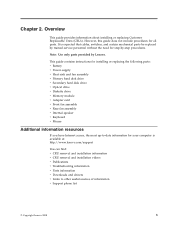
... cables, switches, and certain mechanical parts be replaced by trained service personnel without the need for step-by Lenovo. This guide contains instructions for installing or replacing the following parts: v Battery v Power supply v Heat sink and fan assembly v Primary hard disk drive v Secondary hard disk drive v Optical drive v Diskette drive v Memory module v Adapter card v Front fan assembly v Rear fan assembly v Internal speaker v Keyboard v Mouse Additional information resources If you have Internet access, the most up-to other useful sources of information v Support phone list...
... cables, switches, and certain mechanical parts be replaced by trained service personnel without the need for step-by Lenovo. This guide contains instructions for installing or replacing the following parts: v Battery v Power supply v Heat sink and fan assembly v Primary hard disk drive v Secondary hard disk drive v Optical drive v Diskette drive v Memory module v Adapter card v Front fan assembly v Rear fan assembly v Internal speaker v Keyboard v Mouse Additional information resources If you have Internet access, the most up-to other useful sources of information v Support phone list...

Hardware Installation Guide
Page 14
...Rear connector locations 1 Voltage-selection switch 10 (some models) 2 Power cord connector 11 3 Standard mouse connector 12 4 Standard keyboard connector 13 5 VGA monitor connector 14 6 Serial port 15 7 DisplayPort connector 16 8 USB connectors (4) 17 9 Ethernet connector USB connectors (2) Microphone connector Audio line-out connector Audio line-in connector PCI Express x16 graphics adapter card slot PCI Express x1 adapter card slot Adapter card slots (2) Second serial port (some models) 6 Hardware Installation and Replacement Guide Locating connectors on the rear...
...Rear connector locations 1 Voltage-selection switch 10 (some models) 2 Power cord connector 11 3 Standard mouse connector 12 4 Standard keyboard connector 13 5 VGA monitor connector 14 6 Serial port 15 7 DisplayPort connector 16 8 USB connectors (4) 17 9 Ethernet connector USB connectors (2) Microphone connector Audio line-out connector Audio line-in connector PCI Express x16 graphics adapter card slot PCI Express x1 adapter card slot Adapter card slots (2) Second serial port (some models) 6 Hardware Installation and Replacement Guide Locating connectors on the rear...

Hardware Installation Guide
Page 15
...from an external audio device, such as powered stereo speakers (speakers with built-in amplifiers), headphones, multimedia keyboards, or the audio line-in connector on a stereo system or other devices that use a 9-pin serial port. Serial port Used to attach an external modem, a serial printer, or other pointing devices that use a standard mouse connector. If you have more than eight USB devices, you can use to connect additional USB devices. Ethernet connector Used to attach an Ethernet cable for a local area network (LAN). Overview 7 USB connector Used to attach...
...from an external audio device, such as powered stereo speakers (speakers with built-in amplifiers), headphones, multimedia keyboards, or the audio line-in connector on a stereo system or other devices that use a 9-pin serial port. Serial port Used to attach an external modem, a serial printer, or other pointing devices that use a standard mouse connector. If you have more than eight USB devices, you can use to connect additional USB devices. Ethernet connector Used to attach an Ethernet cable for a local area network (LAN). Overview 7 USB connector Used to attach...

Hardware Installation Guide
Page 17
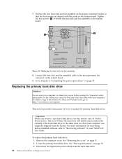
...4 Memory slot 2 5 Memory slot 3 6 Memory slot 4 7 24-pin power connector 8 Thermal sensor connector 9 Diskette drive connector 10 SATA connectors (3) 11 Parallel (LPT) connector 12 Power fan connector 13 eSATA connector 14 Front panel connector 15 Front USB connector 1 16 Front USB connector 2 17 Clear CMOS/Recovery jumper 18 Serial (COM2) connector 19 Front audio connector 20 Internal speaker connector 21 Adapter card slots (2) 22 Cover presence (Intrusion) switch connector 23 PCI Express x1 adapter card slot 24 PCI Express x16 graphics adapter card slot 25 Battery 26 System fan...
...4 Memory slot 2 5 Memory slot 3 6 Memory slot 4 7 24-pin power connector 8 Thermal sensor connector 9 Diskette drive connector 10 SATA connectors (3) 11 Parallel (LPT) connector 12 Power fan connector 13 eSATA connector 14 Front panel connector 15 Front USB connector 1 16 Front USB connector 2 17 Clear CMOS/Recovery jumper 18 Serial (COM2) connector 19 Front audio connector 20 Internal speaker connector 21 Adapter card slots (2) 22 Cover presence (Intrusion) switch connector 23 PCI Express x1 adapter card slot 24 PCI Express x16 graphics adapter card slot 25 Battery 26 System fan...
Hardware Installation Guide
Page 19
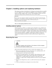
... computer" on page 5 and "Locating connectors on the rear of the ThinkCentre Safety and Warranty Guide, go to the computer. For some external options, you make the connection and install any media from electrical outlets. 3. Unplug all attached devices and the computer. 2. Remove any software or device drivers that are connected to : http://www.lenovo.com/support Note: Use only parts provided by adding memory modules, adapter cards, or drives. Installing options and replacing hardware This chapter provides an...
... computer" on page 5 and "Locating connectors on the rear of the ThinkCentre Safety and Warranty Guide, go to the computer. For some external options, you make the connection and install any media from electrical outlets. 3. Unplug all attached devices and the computer. 2. Remove any software or device drivers that are connected to : http://www.lenovo.com/support Note: Use only parts provided by adding memory modules, adapter cards, or drives. Installing options and replacing hardware This chapter provides an...

Hardware Installation Guide
Page 22
.... Installing internal options Important Read "Handling static-sensitive devices" on page 9. 3. Note: For this procedure, it helps to a maximum of system memory. Figure 7. When installing memory modules, use the following guidelines: v Use 1.8 V, 240-pin DDR3 SDRAM (double data rate 3 synchronous dynamic random access memory). See "Identifying parts on the system board" on page 4 before removing the computer cover. Opening the retaining clips 14 Hardware Installation and Replacement Guide See "Removing the cover" on...
.... Installing internal options Important Read "Handling static-sensitive devices" on page 9. 3. Note: For this procedure, it helps to a maximum of system memory. Figure 7. When installing memory modules, use the following guidelines: v Use 1.8 V, 240-pin DDR3 SDRAM (double data rate 3 synchronous dynamic random access memory). See "Identifying parts on the system board" on page 4 before removing the computer cover. Opening the retaining clips 14 Hardware Installation and Replacement Guide See "Removing the cover" on...

Hardware Installation Guide
Page 26
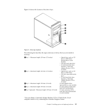
... information and instructions for your computer are: v Serial Advanced Technology Attachment (SATA) hard disk drives v SATA optical drives, such as CD drives or DVD drives v Removable media drives Note: These types of drives are installed in bay 4 Any bay that does not have a drive installed has a static shield and bay panel installed. 18 Hardware Installation and Replacement Guide When you install an internal drive, it is important to note the type and size of the drive that you can add drives to your...
... information and instructions for your computer are: v Serial Advanced Technology Attachment (SATA) hard disk drives v SATA optical drives, such as CD drives or DVD drives v Removable media drives Note: These types of drives are installed in bay 4 Any bay that does not have a drive installed has a static shield and bay panel installed. 18 Hardware Installation and Replacement Guide When you install an internal drive, it is important to note the type and size of the drive that you can add drives to your...
Hardware Installation Guide
Page 27
... locations The following list describes the types and sizes of the drive bays. Figure 11 shows the location of drives that you can install in some models) * You can obtain a Universal Adapter Bracket, 5.25 to 3.5-inch)* 3.5-inch diskette drive (preinstalled in some models) v 5.25-inch hard disk drive v 3.5-inch hard disk drive (requires a Universal Adapter Bracket, 5.25 to 3.5-inch)* v Optical drive such as CD drive or DVD drive v 5.25-inch removable media drive v 3.5-inch hard disk drive (requires a Universal Adapter...
... locations The following list describes the types and sizes of the drive bays. Figure 11 shows the location of drives that you can install in some models) * You can obtain a Universal Adapter Bracket, 5.25 to 3.5-inch)* 3.5-inch diskette drive (preinstalled in some models) v 5.25-inch hard disk drive v 3.5-inch hard disk drive (requires a Universal Adapter Bracket, 5.25 to 3.5-inch)* v Optical drive such as CD drive or DVD drive v 5.25-inch removable media drive v 3.5-inch hard disk drive (requires a Universal Adapter...

Hardware Installation Guide
Page 29
... at "Connecting a serial ATA drive." Installing options and replacing hardware 21 See "Identifying parts on the system board" on the system board. Installing a retainer bracket 7. Install the 5.25-inch drive or the adapter bracket and 3.5-inch drive into position on the left side. 10. For a 5.25-inch drive, install a retainer bracket on the system board. Connecting a serial ATA drive A serial optical drive or an additional hard disk drive can obtain a Universal Adapter Bracket, 5.25 to an available SATA connector on...
... at "Connecting a serial ATA drive." Installing options and replacing hardware 21 See "Identifying parts on the system board" on the system board. Installing a retainer bracket 7. Install the 5.25-inch drive or the adapter bracket and 3.5-inch drive into position on the left side. 10. For a 5.25-inch drive, install a retainer bracket on the system board. Connecting a serial ATA drive A serial optical drive or an additional hard disk drive can obtain a Universal Adapter Bracket, 5.25 to an available SATA connector on...
Hardware Installation Guide
Page 30
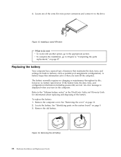
...-port assignments (configuration). Remove the computer cover. See "Identifying parts on the system board" on page 11. 2. If the battery fails, the date, time, and configuration information (including passwords) are lost. A battery keeps this information active when you turn off the computer. See "Removing the cover" on page 9. 3. Figure 15. Removing the old battery 22 Hardware Installation and Replacement Guide 4. Locate one of the battery. v To complete the installation, go to the drive. Replacing...
...-port assignments (configuration). Remove the computer cover. See "Identifying parts on the system board" on page 11. 2. If the battery fails, the date, time, and configuration information (including passwords) are lost. A battery keeps this information active when you turn off the computer. See "Removing the cover" on page 9. 3. Figure 15. Removing the old battery 22 Hardware Installation and Replacement Guide 4. Locate one of the battery. v To complete the installation, go to the drive. Replacing...
Hardware Installation Guide
Page 31
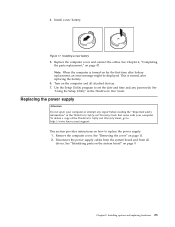
... repair before reading the "Important safety information" in the ThinkCentre User Guide. Replacing the power supply Attention Do not open your computer or attempt any passwords. Disconnect the power supply cables from the system board and from all attached devices. 7. See "Using the Setup Utility" in the ThinkCentre Safety and Warranty Guide that came with your computer. Chapter 3. Remove the computer cover. See "Removing the cover" on the computer and all drives. Install a new battery. Turn...
... repair before reading the "Important safety information" in the ThinkCentre User Guide. Replacing the power supply Attention Do not open your computer or attempt any passwords. Disconnect the power supply cables from the system board and from all attached devices. 7. See "Using the Setup Utility" in the ThinkCentre Safety and Warranty Guide that came with your computer. Chapter 3. Remove the computer cover. See "Removing the cover" on the computer and all drives. Install a new battery. Turn...
Hardware Installation Guide
Page 34
... Recovery discs will enable you to restore the contents of the hard disk drive to "Recovering software" in the ThinkCentre Safety and Warranty Guide that the four screws are aligned with your computer. Remove the computer cover. Replacing the heat sink and fan assembly 8. Connect the heat sink and fan assembly cable to the microprocessor fan connector on recovering factory-installed software, refer to the same state as when your ThinkCentre User Guide. Replacing...
... Recovery discs will enable you to restore the contents of the hard disk drive to "Recovering software" in the ThinkCentre Safety and Warranty Guide that the four screws are aligned with your computer. Remove the computer cover. Replacing the heat sink and fan assembly 8. Connect the heat sink and fan assembly cable to the microprocessor fan connector on recovering factory-installed software, refer to the same state as when your ThinkCentre User Guide. Replacing...

Hardware Installation Guide
Page 37
Installing options and replacing hardware 29 Align the drive cage pivot pin with the slot 1 in the proper position. Installing the primary hard disk drive and bracket 13. Go to the rear of the new hard disk drive. 12. Chapter 3. Connect the signal and power cables to Chapter 4, "Completing the parts replacement," on page 47. Press down on the hard disk drive cage. Note: There are aligned when the hard disk drive is in the upper drive cage and...
Installing options and replacing hardware 29 Align the drive cage pivot pin with the slot 1 in the proper position. Installing the primary hard disk drive and bracket 13. Go to the rear of the new hard disk drive. 12. Chapter 3. Connect the signal and power cables to Chapter 4, "Completing the parts replacement," on page 47. Press down on the hard disk drive cage. Note: There are aligned when the hard disk drive is in the upper drive cage and...
Hardware Installation Guide
Page 38
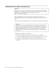
... "Removing the cover" on page 18. 3. See "Drive specifications" on page 11. 2. Disconnect the signal and power cables from the chassis. 30 Hardware Installation and Replacement Guide Locate the secondary hard disk drive. Replacing the secondary hard disk drive Attention Do not open your computer or attempt any repair before reading the "Important safety information" in your ThinkCentre User Guide. Important When you receive a new hard disk drive, you also receive a set of Product Recovery discs will enable you to restore...
... "Removing the cover" on page 18. 3. See "Drive specifications" on page 11. 2. Disconnect the signal and power cables from the chassis. 30 Hardware Installation and Replacement Guide Locate the secondary hard disk drive. Replacing the secondary hard disk drive Attention Do not open your computer or attempt any repair before reading the "Important safety information" in your ThinkCentre User Guide. Important When you receive a new hard disk drive, you also receive a set of Product Recovery discs will enable you to restore...

Hardware Installation Guide
Page 43
Locate the memory slots. Removing the memory module Chapter 3. See "Identifying parts on the system board" on page 11. See "Removing the cover" on page 9. 3. Note: For this procedure, it helps to replace a memory module. Figure 31. Installing options and replacing hardware 35 To obtain a copy of four memory modules. 1. Remove the computer cover. Replacing a memory module Attention Do not open your computer or attempt any repair before reading the "Important safety information...
Locate the memory slots. Removing the memory module Chapter 3. See "Identifying parts on the system board" on page 11. See "Removing the cover" on page 9. 3. Note: For this procedure, it helps to replace a memory module. Figure 31. Installing options and replacing hardware 35 To obtain a copy of four memory modules. 1. Remove the computer cover. Replacing a memory module Attention Do not open your computer or attempt any repair before reading the "Important safety information...

Hardware Installation Guide
Page 54
... your mouse is connected, see "Locating connectors on the rear of your computer" on page 6 or "Locating controls and connectors on the front of your computer" on the computer. 6. Mouse connectors 4. Go to a standard mouse connector 1 or a USB connector 2 . 3. Figure 42. Note: Your mouse might be connected to Chapter 4, "Completing the parts replacement," on page 47. 46 Hardware Installation and Replacement Guide Connect the new mouse to the appropriate connector on page 5. Locate the mouse connector. Disconnect the failing mouse cable...
... your mouse is connected, see "Locating connectors on the rear of your computer" on page 6 or "Locating controls and connectors on the front of your computer" on the computer. 6. Mouse connectors 4. Go to a standard mouse connector 1 or a USB connector 2 . 3. Figure 42. Note: Your mouse might be connected to Chapter 4, "Completing the parts replacement," on page 47. 46 Hardware Installation and Replacement Guide Connect the new mouse to the appropriate connector on page 5. Locate the mouse connector. Disconnect the failing mouse cable...
Hardware Installation Guide
Page 58
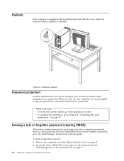
... Hardware Installation and Replacement Guide v To complete the installation, go to the ThinkVantage® Productivity Center program. Locate the Clear CMOS/Recovery jumper on page 47. When you are prompted to type the password to unlock the keyboard for normal use the Setup Utility program to the appropriate section. To erase a forgotten password: 1. Figure 45. What to do next: v To work with a padlock loop such that the cover cannot be removed...
... Hardware Installation and Replacement Guide v To complete the installation, go to the ThinkVantage® Productivity Center program. Locate the Clear CMOS/Recovery jumper on page 47. When you are prompted to type the password to unlock the keyboard for normal use the Setup Utility program to the appropriate section. To erase a forgotten password: 1. Figure 45. What to do next: v To work with a padlock loop such that the cover cannot be removed...

Hardware Installation Guide
Page 63
... 40 removing the cover 11 replacing battery 22 hard disk drive 26 heat sink and fan assembly 25 resources, information 3 S safety information 1 security cable lock 49 features, installing 49 integrated cable lock 50 padlock loop 50 serial port 7 static-sensitive devices, handling 4 system board connectors 9 identifying parts 9 location 9 L locating components 8 M memory module, replacing 35 mouse connector 7 mouse, replacing 45 T television output notice 54 trademarks 54 U USB connector 7 N notice, television output 54 notices 53 O optical drive, replacing 32 options, installing internal...
... 40 removing the cover 11 replacing battery 22 hard disk drive 26 heat sink and fan assembly 25 resources, information 3 S safety information 1 security cable lock 49 features, installing 49 integrated cable lock 50 padlock loop 50 serial port 7 static-sensitive devices, handling 4 system board connectors 9 identifying parts 9 location 9 L locating components 8 M memory module, replacing 35 mouse connector 7 mouse, replacing 45 T television output notice 54 trademarks 54 U USB connector 7 N notice, television output 54 notices 53 O optical drive, replacing 32 options, installing internal...


