Hardware Maintenance Manual
Page 5
... . 29 The ThinkVantage Productivity Center program . . 29 Additional information resources 29 Specifications 29 Types 7066, 7098, 9352, 9359, 9482, 9487, 9622, 9704, 9794, 9859, 9785, 9807, 9952 . . 29 Types 7065, 7096, 9351, 9358, 9438, 9481, 9489, 9703, 9784, 9788, 9792, ...4. General Checkout. . . . . 33 Problem determination tips 33 Chapter 5. Symptom-to-FRU Index . 45 Hard disk drive boot error 45 Power Supply Problems 45 Diagnostic error codes 46 Beep symptoms 63 POST error codes 64 Miscellaneous error ... 9708, 9709, 9789, 9851, 9948 91 © Copyright Lenovo 2005, 2010 v
... . 29 The ThinkVantage Productivity Center program . . 29 Additional information resources 29 Specifications 29 Types 7066, 7098, 9352, 9359, 9482, 9487, 9622, 9704, 9794, 9859, 9785, 9807, 9952 . . 29 Types 7065, 7096, 9351, 9358, 9438, 9481, 9489, 9703, 9784, 9788, 9792, ...4. General Checkout. . . . . 33 Problem determination tips 33 Chapter 5. Symptom-to-FRU Index . 45 Hard disk drive boot error 45 Power Supply Problems 45 Diagnostic error codes 46 Beep symptoms 63 POST error codes 64 Miscellaneous error ... 9708, 9709, 9789, 9851, 9948 91 © Copyright Lenovo 2005, 2010 v

Hardware Maintenance Manual
Page 6
...PCI adapter 104 Replacing the primary hard disk drive. . . . . . 105 Replacing the secondary hard disk drive . . . . 108 Replacing an optical drive 111 Replacing the diskette drive 111 Replacing the rear fan ...drive 137 Replacing the diskette drive 138 Replacing the fan assembly 140 Completing the FRU replacement 141 Chapter 11. FRU lists 143 Machine Type 6176 143 Machine Type 6177 158 Machine Type 6178 173 Machine Type 6179 187 vi ThinkCentre...9622 540 Machine Type 9702 554 Machine Type 9703 572 Machine Type 9704 588 Machine Type 9708 605 Machine Type 9788 621 Machine Type ...
...PCI adapter 104 Replacing the primary hard disk drive. . . . . . 105 Replacing the secondary hard disk drive . . . . 108 Replacing an optical drive 111 Replacing the diskette drive 111 Replacing the rear fan ...drive 137 Replacing the diskette drive 138 Replacing the fan assembly 140 Completing the FRU replacement 141 Chapter 11. FRU lists 143 Machine Type 6176 143 Machine Type 6177 158 Machine Type 6178 173 Machine Type 6179 187 vi ThinkCentre...9622 540 Machine Type 9702 554 Machine Type 9703 572 Machine Type 9704 588 Machine Type 9708 605 Machine Type 9788 621 Machine Type ...
Hardware Maintenance Manual
Page 41
...; Machine type and model • Processor or hard disk upgrades • Failure symptom - Check all external devices. 2. Power-on the display. If you select an incorrect drive. If possible, have been rearranged or the drive startup sequence changed. Do diagnostics indicate a failure?... - General Checkout Attention The drives in problem determination. Run the Diagnostic programs. See Chapter 5 "Diagnostics" on page 775. Is the failure repeatable? © Copyright Lenovo 2005, 2010 33 For an explanation of the system board. For...
...; Machine type and model • Processor or hard disk upgrades • Failure symptom - Check all external devices. 2. Power-on the display. If you select an incorrect drive. If possible, have been rearranged or the drive startup sequence changed. Do diagnostics indicate a failure?... - General Checkout Attention The drives in problem determination. Run the Diagnostic programs. See Chapter 5 "Diagnostics" on page 775. Is the failure repeatable? © Copyright Lenovo 2005, 2010 33 For an explanation of the system board. For...
Hardware Maintenance Manual
Page 46
... Errors reported by the diagnostic test will be displayed by the program as a failed test. 38 ThinkCentre Hardware Maintenance Manual hard drive The diagnostics program offers two hard drive format utilities: • Quick Erase Hard Drive • Full Erase Hard Drive The Quick Erase Hard Drive provides a DOS utility that performs the following : • Performs all the steps in Quick Erase...
... Errors reported by the diagnostic test will be displayed by the program as a failed test. 38 ThinkCentre Hardware Maintenance Manual hard drive The diagnostics program offers two hard drive format utilities: • Quick Erase Hard Drive • Full Erase Hard Drive The Quick Erase Hard Drive provides a DOS utility that performs the following : • Performs all the steps in Quick Erase...

Hardware Maintenance Manual
Page 50
... press and release the F12 key rather than leaving it deters unauthorized persons from the Startup Device Menu and press Enter to begin. 42 ThinkCentre Hardware Maintenance Manual When the Startup Device Menu appears, release the F12 key. However, to startup from the keyboard. Start the Setup Utility... Device Menu does not display using this procedure to change any configuration settings, you must use the space bar • Setup Utility program and hard disk drive passwords are not case sensitive • Not be your name or your user name • Not be a common word or a common name...
... press and release the F12 key rather than leaving it deters unauthorized persons from the Startup Device Menu and press Enter to begin. 42 ThinkCentre Hardware Maintenance Manual When the Startup Device Menu appears, release the F12 key. However, to startup from the keyboard. Start the Setup Utility... Device Menu does not display using this procedure to change any configuration settings, you must use the space bar • Setup Utility program and hard disk drive passwords are not case sensitive • Not be your name or your user name • Not be a common word or a common name...

Hardware Maintenance Manual
Page 53
... you suspect a power problem, use the following causes. Using the operating systems programs, format the hard disk drive. Error The start -up the data on Switch © Copyright Lenovo 2005, 2010 45 The boot sector on page 67. The drive is listed first. Chapter 7. If you did receive a POST error message, diagnose the POST...
... you suspect a power problem, use the following causes. Using the operating systems programs, format the hard disk drive. Error The start -up the data on Switch © Copyright Lenovo 2005, 2010 45 The boot sector on page 67. The drive is listed first. Chapter 7. If you did receive a POST error message, diagnose the POST...
Hardware Maintenance Manual
Page 57
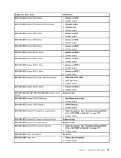
...001-301-XXX System RTC Century byte error 005-000-XXX Video Test Passed 005-00X-XXX Video error FRU/Action 1. Diskette drive 3. System board 1. System board 1. Hard disk drive 3. System board 1. Run Setup and re-test 2. See "Updating (flashing) BIOS from a CD-ROM or diskette" ...board 1. System board 1. Device on IRQ9 2. Flash the system. Symptom-to-FRU Index 49 Diskette Cable 2. Device on IRQ15 2. Device on IRQ8 2. Hard disk drive cable 2. System board 1. Device on IRQ12 2. Flash the system. See "Updating (flashing) BIOS from a CD-ROM or diskette" on IRQ10 2. ...
...001-301-XXX System RTC Century byte error 005-000-XXX Video Test Passed 005-00X-XXX Video error FRU/Action 1. Diskette drive 3. System board 1. System board 1. Hard disk drive 3. System board 1. Run Setup and re-test 2. See "Updating (flashing) BIOS from a CD-ROM or diskette" ...board 1. System board 1. Device on IRQ9 2. Flash the system. Symptom-to-FRU Index 49 Diskette Cable 2. Device on IRQ15 2. Device on IRQ8 2. Hard disk drive cable 2. System board 1. Device on IRQ12 2. Flash the system. See "Updating (flashing) BIOS from a CD-ROM or diskette" on IRQ10 2. ...

Hardware Maintenance Manual
Page 70
... action 1. Flash the system and re-test. Check Power supply voltages 3. Flash system 2. Diskette Drive Cable 2. Reseat the hard disk drive cable 4. Hard Disk drive (IDE) 5. C2 Cover Switch 3. Replace the memory module called out by the test 2. System board 62 ThinkCentre Hardware Maintenance Manual Microprocessor 4. System board 3. Check power supply voltages 3. Diagnostic Error Code 175...
... action 1. Flash the system and re-test. Check Power supply voltages 3. Flash system 2. Diskette Drive Cable 2. Reseat the hard disk drive cable 4. Hard Disk drive (IDE) 5. C2 Cover Switch 3. Replace the memory module called out by the test 2. System board 62 ThinkCentre Hardware Maintenance Manual Microprocessor 4. System board 3. Check power supply voltages 3. Diagnostic Error Code 175...

Hardware Maintenance Manual
Page 71
..." on page 776. Start the Setup Utility program and press F7 to load defaults and then press F10 to enable DDC 2. Reseat the hard disk drive cable 4. Cable 3. The following tables describes beep symptoms. Beep Symptom 2 short beeps CMOS setting error FRU/Action Perform the following actions in...test the system Beep symptoms Beep symptoms are tones or a series of tones separated by pauses (intervals without sound) during POST. Hard Disk Drive Cable 2. Check and test Keyboard 3. Mouse 2. See "Recovering from a POST/BIOS update failure" on page 41. 2. Remove the Hi-...
..." on page 776. Start the Setup Utility program and press F7 to load defaults and then press F10 to enable DDC 2. Reseat the hard disk drive cable 4. Cable 3. The following tables describes beep symptoms. Beep Symptom 2 short beeps CMOS setting error FRU/Action Perform the following actions in...test the system Beep symptoms Beep symptoms are tones or a series of tones separated by pauses (intervals without sound) during POST. Hard Disk Drive Cable 2. Check and test Keyboard 3. Mouse 2. See "Recovering from a POST/BIOS update failure" on page 41. 2. Remove the Hi-...
Hardware Maintenance Manual
Page 73
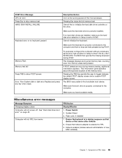
... the memory areas being tested. This information gives specifics about the type and location of new MAC address) Chapter 7. See "Hard disk drive boot error" on page 45. Network adapter (Advise network administrator of the memory error. Pressing the TAB key permits the user...network is correctly installed. To purposely configure the computer without a keyboard, set to find or initialize the hard disk drive controller or the drive. Ensure that no hard disk drives are held pressed during POST. Make sure you have bootable media. The BIOS was unable to NONE....
... the memory areas being tested. This information gives specifics about the type and location of new MAC address) Chapter 7. See "Hard disk drive boot error" on page 45. Network adapter (Advise network administrator of the memory error. Pressing the TAB key permits the user...network is correctly installed. To purposely configure the computer without a keyboard, set to find or initialize the hard disk drive controller or the drive. Ensure that no hard disk drives are held pressed during POST. Make sure you have bootable media. The BIOS was unable to NONE....

Hardware Maintenance Manual
Page 74
... blank 1. System Board No power or fan not running 1. System Board 3. System Board 66 ThinkCentre Hardware Maintenance Manual System Board 2. Network Adapter Intensity or color varies from left to enable Wake on page 45. See "Hard disk drive boot error" on page 41) 4. Ensure that the operating system settings are set to right...
... blank 1. System Board No power or fan not running 1. System Board 3. System Board 66 ThinkCentre Hardware Maintenance Manual System Board 2. Network Adapter Intensity or color varies from left to enable Wake on page 45. See "Hard disk drive boot error" on page 41) 4. Ensure that the operating system settings are set to right...
Hardware Maintenance Manual
Page 75
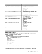
... port device failure (system board port) 1. External Device 3. Any adapters c. Diskette drive 3. hard disk 2. System Board Serial or parallel port device failure (adapter port) 1. Cable 4. Memory modules d. Hard disk drive h. If all keys on the computer to -FRU Index 67 RPL, check startup ...until you find the failing device or adapter. Message/Symptom FRU/Action Program loads from the hard disk with a known-good diagnostics diskette in the first 3.5-inch diskette drive 1. System Board Some or all devices and adapters have been removed, and the problem continues...
... port device failure (system board port) 1. External Device 3. Any adapters c. Diskette drive 3. hard disk 2. System Board Serial or parallel port device failure (adapter port) 1. Cable 4. Memory modules d. Hard disk drive h. If all keys on the computer to -FRU Index 67 RPL, check startup ...until you find the failing device or adapter. Message/Symptom FRU/Action Program loads from the hard disk with a known-good diagnostics diskette in the first 3.5-inch diskette drive 1. System Board Some or all devices and adapters have been removed, and the problem continues...

Hardware Maintenance Manual
Page 78
... components The following illustration will help you locate the major FRUs in the computer. 1 Fan plenum, fan, and heat sink 2 Microprocessor 3 Optical drive 4 Power switch/LED assembly 5 Hard disk drive 6 Diskette drive 7 Front panel card 8 Memory modules 9 System board 10 Power supply System board connectors This illustration is to help locate the various system...
... components The following illustration will help you locate the major FRUs in the computer. 1 Fan plenum, fan, and heat sink 2 Microprocessor 3 Optical drive 4 Power switch/LED assembly 5 Hard disk drive 6 Diskette drive 7 Front panel card 8 Memory modules 9 System board 10 Power supply System board connectors This illustration is to help locate the various system...

Hardware Maintenance Manual
Page 83
... board must be displayed. Also remove the screw that has this label attached. See "Accessing system board components and drives" on page 71. 2. Note: Observe the power supply cable routing underneath the hard disk drive. 5. Replacing FRUs (Types 7065, 7096, 9351, 9358, 9438, 9481, 9489, 9703, 9784, 9788, 9792,...Note: You do not have to the chassis and slide the system board away from the power supply. Chapter 8. See "Replacing the hard disk drive" on a power supply or any PCI adapters that secure the power supply. See the system board diagram for the first time after replacing...
... board must be displayed. Also remove the screw that has this label attached. See "Accessing system board components and drives" on page 71. 2. Note: Observe the power supply cable routing underneath the hard disk drive. 5. Replacing FRUs (Types 7065, 7096, 9351, 9358, 9438, 9481, 9489, 9703, 9784, 9788, 9792,...Note: You do not have to the chassis and slide the system board away from the power supply. Chapter 8. See "Replacing the hard disk drive" on a power supply or any PCI adapters that secure the power supply. See the system board diagram for the first time after replacing...
Hardware Maintenance Manual
Page 91
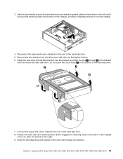
... the bracket, and align the pins 1 through 4 on the bottom of the chassis when you slide the bracket to the right. 9. Position the hard disk drive and bracket so that it engages the retaining clips in the bottom of the chassis, and then completely remove it is free of the retaining... clips in the bottom of the hard disk drive. 7. Slide the hard disk drive and bracket to the rear of the hard disk drive. 5. Remove the blue bracket from the rear of the hard disk drive. 8. Do not touch the circuit board 5 on the bracket with the holes ...
... the bracket, and align the pins 1 through 4 on the bottom of the chassis when you slide the bracket to the right. 9. Position the hard disk drive and bracket so that it engages the retaining clips in the bottom of the chassis, and then completely remove it is free of the retaining... clips in the bottom of the hard disk drive. 7. Slide the hard disk drive and bracket to the rear of the hard disk drive. 5. Remove the blue bracket from the rear of the hard disk drive. 8. Do not touch the circuit board 5 on the bracket with the holes ...
Hardware Maintenance Manual
Page 105
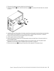
... board out of all cable connections on page 92. 11. Press the release tab 1 down, slide the hard drive cage 2 back, and pivot the hard disk drive outward as shown. 6. Remove the memory modules from the hard disk drive. 5. See the system board illustration for your machine type at "System board connectors" on the new system...
... board out of all cable connections on page 92. 11. Press the release tab 1 down, slide the hard drive cage 2 back, and pivot the hard disk drive outward as shown. 6. Remove the memory modules from the hard disk drive. 5. See the system board illustration for your machine type at "System board connectors" on the new system...
Hardware Maintenance Manual
Page 113
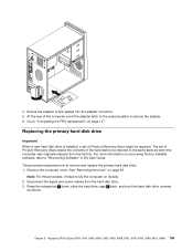
... Press the release tab 1 down, slide the hard drive cage 2 back, and pivot the hard disk drive outward as when the computer was originally shipped from the hard disk drive. 3. Chapter 9. Replacing the primary hard disk drive Important When a new hard disk drive is fully seated into the adapter connector. 5. ...on page 117. Go to secure the adapter. 6. Note: For this procedure, it helps to remove and replace the primary hard disk drive. 1. This procedure describes how to lay the computer on recovering factory-installed software, refer to the same state as shown. Remove...
... Press the release tab 1 down, slide the hard drive cage 2 back, and pivot the hard disk drive outward as when the computer was originally shipped from the hard disk drive. 3. Chapter 9. Replacing the primary hard disk drive Important When a new hard disk drive is fully seated into the adapter connector. 5. ...on page 117. Go to secure the adapter. 6. Note: For this procedure, it helps to remove and replace the primary hard disk drive. 1. This procedure describes how to lay the computer on recovering factory-installed software, refer to the same state as shown. Remove...
Hardware Maintenance Manual
Page 116
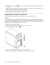
... be restored to release the hard drive cage from the hard disk drive. 4. Locate the secondary hard disk drive 5 . 3. Note: There are two arrows, one on the upper drive cage and one on how to the hard disk drive. 12. To replace the secondary hard disk drive: 1. Disconnect the signal and power cables from the chassis. 108 ThinkCentre Hardware Maintenance Manual Connect...
... be restored to release the hard drive cage from the hard disk drive. 4. Locate the secondary hard disk drive 5 . 3. Note: There are two arrows, one on the upper drive cage and one on how to the hard disk drive. 12. To replace the secondary hard disk drive: 1. Disconnect the signal and power cables from the chassis. 108 ThinkCentre Hardware Maintenance Manual Connect...
Hardware Maintenance Manual
Page 117
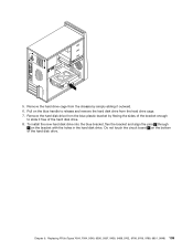
...slide it outward. 6. Remove the hard disk drive from the blue plastic bracket by simply sliding it free of the hard disk drive. 8. Chapter 9. Do not touch the circuit board 5 on the bracket with the holes in the hard disk drive. To install the new hard disk drive into the blue bracket, flex the... bracket and align the pins 1 through 4 on the bottom of the bracket enough to release and remove the hard disk drive from the chassis by flexing the sides of the hard disk drive. Replacing FRUs (Types 7064, 7094, 9349, 9356, 9357, 9439, 9488, 9702, 9708, 9709, 9789, 9851, 9948...
...slide it outward. 6. Remove the hard disk drive from the blue plastic bracket by simply sliding it free of the hard disk drive. 8. Chapter 9. Do not touch the circuit board 5 on the bracket with the holes in the hard disk drive. To install the new hard disk drive into the blue bracket, flex the... bracket and align the pins 1 through 4 on the bottom of the bracket enough to release and remove the hard disk drive from the chassis by flexing the sides of the hard disk drive. Replacing FRUs (Types 7064, 7094, 9349, 9356, 9357, 9439, 9488, 9702, 9708, 9709, 9789, 9851, 9948...
Hardware Maintenance Manual
Page 118
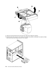
9. Slide the new hard disk drive into the hard drive cage until it snaps into position underneath the metal tab. Install the hard drive cage into the chassis until it snaps into position. 10. Make sure that the hard drive cage is secure in the chassis. 110 ThinkCentre Hardware Maintenance Manual
9. Slide the new hard disk drive into the hard drive cage until it snaps into position underneath the metal tab. Install the hard drive cage into the chassis until it snaps into position. 10. Make sure that the hard drive cage is secure in the chassis. 110 ThinkCentre Hardware Maintenance Manual


