Brochure
Page 3
...Lenovo Care ThinkVantage® Rescue and Recovery® ThinkVantage System Update ThinkVantage Client Security Solution ThinkVantage Fingerprint Software ThinkVantage Power Manager GO GREEN WITH THE THINKCENTRE A58 DESKTOP The A58 is an EPEAT™ Gold certified ThinkCentre for media card reader Power Supply...;ce Professional 2007 60-Day Trial Version Microsoft® Windows Live™ Portal McAfee® VirusScan® Plus with Lenovo's energy-saving ThinkVision® monitors and keyboards provides a low energy consumption solution. 3 All form factors have select models...
...Lenovo Care ThinkVantage® Rescue and Recovery® ThinkVantage System Update ThinkVantage Client Security Solution ThinkVantage Fingerprint Software ThinkVantage Power Manager GO GREEN WITH THE THINKCENTRE A58 DESKTOP The A58 is an EPEAT™ Gold certified ThinkCentre for media card reader Power Supply...;ce Professional 2007 60-Day Trial Version Microsoft® Windows Live™ Portal McAfee® VirusScan® Plus with Lenovo's energy-saving ThinkVision® monitors and keyboards provides a low energy consumption solution. 3 All form factors have select models...
User Manual
Page 5
... . 55 Hard disk drive boot error 55 Power supply problems 55 Diagnostic error codes 56 Beep symptoms 77 POST error codes 78 Miscellaneous error messages 80 Undetermined problems 81 Chapter 8. Diagnostics 45 Lenovo ThinkVantage Toolbox 45 Lenovo System Toolbox 45 PC-Doctor for Rescue and ... . . . 89 Installing or replacing a memory module . . . . 90 Installing or replacing a PCI card 92 Replacing the battery 95 Replacing the power supply assembly . . . . . 96 Replacing the heat sink and fan assembly . . . . 98 Replacing the microprocessor 100 Replacing the system board 103 Replacing...
... . 55 Hard disk drive boot error 55 Power supply problems 55 Diagnostic error codes 56 Beep symptoms 77 POST error codes 78 Miscellaneous error messages 80 Undetermined problems 81 Chapter 8. Diagnostics 45 Lenovo ThinkVantage Toolbox 45 Lenovo System Toolbox 45 PC-Doctor for Rescue and ... . . . 89 Installing or replacing a memory module . . . . 90 Installing or replacing a PCI card 92 Replacing the battery 95 Replacing the power supply assembly . . . . . 96 Replacing the heat sink and fan assembly . . . . 98 Replacing the microprocessor 100 Replacing the system board 103 Replacing...
User Manual
Page 10
...pocket or behind your body. - v Do not use this type of maintenance information. Some hand tools have , near power supplies - Working near their equipment, rubber floor mats that has hazardous voltages. v If you need to protect yourself from electrical...workstation covers, unless instructed otherwise in the off the power, if necessary. - To avoid personal injury or equipment damage, disconnect the attached power cords, telecommunication systems, networks, and modems before : - v Never assume that supplies power to the machine and to switch off position. Performing...
...pocket or behind your body. - v Do not use this type of maintenance information. Some hand tools have , near power supplies - Working near their equipment, rubber floor mats that has hazardous voltages. v If you need to protect yourself from electrical...workstation covers, unless instructed otherwise in the off the power, if necessary. - To avoid personal injury or equipment damage, disconnect the attached power cords, telecommunication systems, networks, and modems before : - v Never assume that supplies power to the machine and to switch off position. Performing...
User Manual
Page 11
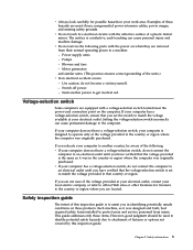
Power supply units - Blowers and fans - Motor generators and similar units. (This practice ensures correct grounding of the following parts with the power on these hazards are moist floors, nongrounded power extension cables, power surges, and missing safety grounds. If your work area. ...surface is designed to official Web sites or other literature for possible hazards in a machine: - Safety information 5 Switch off power. - Setting the voltage-selection switch incorrectly can cause personal injury and machine damage. Examples of the voltage provided at the ...
Power supply units - Blowers and fans - Motor generators and similar units. (This practice ensures correct grounding of the following parts with the power on these hazards are moist floors, nongrounded power extension cables, power surges, and missing safety grounds. If your work area. ...surface is designed to official Web sites or other literature for possible hazards in a machine: - Safety information 5 Switch off power. - Setting the voltage-selection switch incorrectly can cause personal injury and machine damage. Examples of the voltage provided at the ...
User Manual
Page 12
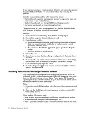
... between objects. v Wear a grounded wrist strap against ESD damage by equalizing the charge so that the power-supply cover fasteners (screws or rivets) have been certified (ISO 9000) as to electrostatic discharge (ESD). Power-off , and the power cord disconnected. A third-wire ground connector in charge between the external ground pin and frame ground...
... between objects. v Wear a grounded wrist strap against ESD damage by equalizing the charge so that the power-supply cover fasteners (screws or rivets) have been certified (ISO 9000) as to electrostatic discharge (ESD). Power-off , and the power cord disconnected. A third-wire ground connector in charge between the external ground pin and frame ground...

User Manual
Page 16
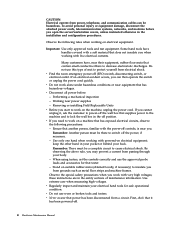
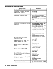
The device also might have more than one power cord. CAUTION: The power control button on the device and the power switch on the power supply do not turn off the electrical current supplied to the device. To remove all electrical current from the device, ensure that all power cords are disconnected from the power source. 2 1 10 Hardware Maintenance Manual
The device also might have more than one power cord. CAUTION: The power control button on the device and the power switch on the power supply do not turn off the electrical current supplied to the device. To remove all electrical current from the device, ensure that all power cords are disconnected from the power source. 2 1 10 Hardware Maintenance Manual

User Manual
Page 61
...drive. 2. Using the operating systems programs, format the hard disk drive. v Power Cord v On/Off Switch connector v On/Off Switch Power Supply connector v System Board Power Supply connectors v Microprocessor(s) connection Check the power cord for proper installation. Always begin with Chapter 4, "General checkout," on the ...up the data on the start -up drive is in configuration. No operating system installed on Switch © Copyright Lenovo 2009 55 FRU/Action Check the configuration and ensure the start -up drive is corrupted. Check/Verify Check the following ...
...drive. 2. Using the operating systems programs, format the hard disk drive. v Power Cord v On/Off Switch connector v On/Off Switch Power Supply connector v System Board Power Supply connectors v Microprocessor(s) connection Check the power cord for proper installation. Always begin with Chapter 4, "General checkout," on the ...up the data on the start -up drive is in configuration. No operating system installed on Switch © Copyright Lenovo 2009 55 FRU/Action Check the configuration and ensure the start -up drive is corrupted. Check/Verify Check the following ...

User Manual
Page 73
... file 2. See Chapter 6, "Using the Setup Utility program," on page 81 1. See "Updating (flashing) BIOS from a disc" on page 51 2. System board No action 1. Check power supply voltages 3. PCI card 2. Make sure the component that is called out in warning statement 4. Go to reset the log file 1. Replace component under test 1. PCI...
... file 2. See Chapter 6, "Using the Setup Utility program," on page 81 1. See "Updating (flashing) BIOS from a disc" on page 51 2. System board No action 1. Check power supply voltages 3. PCI card 2. Make sure the component that is called out in warning statement 4. Go to reset the log file 1. Replace component under test 1. PCI...

User Manual
Page 74
...board Information only Re-start the test to "Undetermined problems" on page 81 2. Make sure the component that is connected and/or enabled. Check power supply 3. SCSI adapter card, if installed 5. System board 1. IDE device 5. Press F3 to "Undetermined problems" on page 81 1. See Chapter 6,... interface Test Passed 030-00X-XXX 030-01X-XXX SCSI interface failure FRU/Action 1. Replace the component under function test No action 1. Check power supply 3. SCSI signal cable 2. Flash the system. See "Updating (flashing) BIOS from a disc" on page 278 3. IDE device 5. IDE...
...board Information only Re-start the test to "Undetermined problems" on page 81 2. Make sure the component that is connected and/or enabled. Check power supply 3. SCSI adapter card, if installed 5. System board 1. IDE device 5. Press F3 to "Undetermined problems" on page 81 1. See Chapter 6,... interface Test Passed 030-00X-XXX 030-01X-XXX SCSI interface failure FRU/Action 1. Replace the component under function test No action 1. Check power supply 3. SCSI signal cable 2. Flash the system. See "Updating (flashing) BIOS from a disc" on page 278 3. IDE device 5. IDE...

User Manual
Page 75
Check power supply 3. Press F3 to "Undetermined problems" on page 81 1. Re-run test 3. Replace the component that is called out is connected and/or enabled. Go to ...
Check power supply 3. Press F3 to "Undetermined problems" on page 81 1. Re-run test 3. Replace the component that is called out is connected and/or enabled. Go to ...

User Manual
Page 80
... log file 2. Replace the component under function test 170-250-XXX 170-251-XXX Voltage Sensor(s) Voltage limit error 1. Flash the system and re-test. Power supply 2. Re-run test 3. Replace the component under test 74 Hardware Maintenance Manual Diagnostic error code FRU/Action 170-197-XXX Voltage Sensor(s) test warning 1. Microprocessor...
... log file 2. Replace the component under function test 170-250-XXX 170-251-XXX Voltage Sensor(s) Voltage limit error 1. Flash the system and re-test. Power supply 2. Re-run test 3. Replace the component under test 74 Hardware Maintenance Manual Diagnostic error code FRU/Action 170-197-XXX Voltage Sensor(s) test warning 1. Microprocessor...

User Manual
Page 81
Replace component under function test 1. Check power supply voltages 3. Go to -FRU index 75 See "Updating (flashing) BIOS from a disc" on page 81 1. Check fans 2. Microprocessor 4. Assure Asset Security Enabled 2. Replace the memory ... Test Passed 206-XXX-XXX Diskette Drive error 215-000-XXX CD-ROM Drive Test Passed FRU/Action 1. Flash the system and re-test. Check Power supply voltages 3. System board 1. System board No action 1. System board No action Chapter 7. See "Undetermined problems" on page 278 3. Flash the system and re-test. C2...
Replace component under function test 1. Check power supply voltages 3. Go to -FRU index 75 See "Updating (flashing) BIOS from a disc" on page 81 1. Check fans 2. Microprocessor 4. Assure Asset Security Enabled 2. Replace the memory ... Test Passed 206-XXX-XXX Diskette Drive error 215-000-XXX CD-ROM Drive Test Passed FRU/Action 1. Flash the system and re-test. Check Power supply voltages 3. System board 1. System board No action 1. System board No action Chapter 7. See "Undetermined problems" on page 278 3. Flash the system and re-test. C2...

User Manual
Page 82
... FRU/Action 1. Keyboard 2. Check and test mouse 3. CD-ROM drive 4. Hard Disk Drive Cable 2. Check power supply voltages 3. Run Setup to enable DDC 2. Hard Disk drive (SCSI) 5. Mouse 2. Cable 3. Monitor 4. CD-ROM Drive Cable 2. Check power supply voltages 3. Check power supply voltages 3. System board No action No action 1. System board No action 76 Hardware Maintenance Manual
... FRU/Action 1. Keyboard 2. Check and test mouse 3. CD-ROM drive 4. Hard Disk Drive Cable 2. Check power supply voltages 3. Run Setup to enable DDC 2. Hard Disk drive (SCSI) 5. Mouse 2. Cable 3. Monitor 4. CD-ROM Drive Cable 2. Check power supply voltages 3. Check power supply voltages 3. System board No action No action 1. System board No action 76 Hardware Maintenance Manual
User Manual
Page 86
... or color varies from server Computer will not perform a Wake on LAN (if applicable) Dead computer. Power Switch 2. Diskette Drive 2. See "Power supply problems" on page 55. Computer will not power-off. System Board 3. System Board 2. Display 2. See "Power supply problems" on page 55. 80 Hardware Maintenance Manual Incorrect memory size during POST ″Insert a Diskette...
... or color varies from server Computer will not perform a Wake on LAN (if applicable) Dead computer. Power Switch 2. Diskette Drive 2. See "Power supply problems" on page 55. Computer will not power-off. System Board 3. System Board 2. Display 2. See "Power supply problems" on page 55. 80 Hardware Maintenance Manual Incorrect memory size during POST ″Insert a Diskette...
User Manual
Page 87
...make sure that the hard disk drive is jumpered as a master and the optical drive is using LCCM Hybrid RPL, check startup sequence: a. Power-off the computer. 2. Any adapters Chapter 7. Diskette Drive Cable Other display symptoms not listed above (including blank or illegible display) 1. Check...disk drive in the first 3.5-inch diskette drive 1. Printer 2. Run Setup and check Startup sequence. 2. Diskette Drive Cable 4. Power Supply RPL computer cannot access programs from its own hard disk. 1. Second device - hard disk 2. Check the network adapter LED status...
...make sure that the hard disk drive is jumpered as a master and the optical drive is using LCCM Hybrid RPL, check startup sequence: a. Power-off the computer. 2. Any adapters Chapter 7. Diskette Drive Cable Other display symptoms not listed above (including blank or illegible display) 1. Check...disk drive in the first 3.5-inch diskette drive 1. Printer 2. Run Setup and check Startup sequence. 2. Diskette Drive Cable 4. Power Supply RPL computer cannot access programs from its own hard disk. 1. Second device - hard disk 2. Check the network adapter LED status...

User Manual
Page 94
Figure 4. Locating components To remove the computer cover, see "Removing the computer cover" on page 86. Component locations 1 Heat sink and fan assembly 2 Memory modules 3 Battery 4 PCI Express x16 graphics card slot 5 PCI card 6 PCI card slot 7 PCI Express x1 card slot 8 Cover presence switch (Intrusion switch) (some models) 9 Rear fan assembly 10 Power supply assembly 88 Hardware Maintenance Manual Figure 4 shows the locations of the various components in your computer.
Figure 4. Locating components To remove the computer cover, see "Removing the computer cover" on page 86. Component locations 1 Heat sink and fan assembly 2 Memory modules 3 Battery 4 PCI Express x16 graphics card slot 5 PCI card 6 PCI card slot 7 PCI Express x1 card slot 8 Cover presence switch (Intrusion switch) (some models) 9 Rear fan assembly 10 Power supply assembly 88 Hardware Maintenance Manual Figure 4 shows the locations of the various components in your computer.
User Manual
Page 102
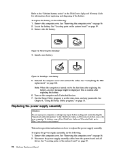
...battery, an error message might be displayed. To replace the battery, do the following : 1. Remove the computer cover. Disconnect the power supply assembly cables from the system board and all attached devices. 7. Remove the computer cover. Removing the old battery 4. Reinstall the ...the Setup Utility program," on how to replace the power supply assembly. See "Locating parts on the system board" on for information about replacing and disposing of the ThinkCentre Safety and Warranty Guide, go to: http://www.lenovo.com/support This section provides instructions on page 51....
...battery, an error message might be displayed. To replace the battery, do the following : 1. Remove the computer cover. Disconnect the power supply assembly cables from the system board and all attached devices. 7. Remove the computer cover. Removing the old battery 4. Reinstall the ...the Setup Utility program," on how to replace the power supply assembly. See "Locating parts on the system board" on for information about replacing and disposing of the ThinkCentre Safety and Warranty Guide, go to: http://www.lenovo.com/support This section provides instructions on page 51....
User Manual
Page 103
.... 7. Install the four screws to 115 V. Reconnect a power supply assembly connector to each of hardware, go to do next: v To work with those in your electrical outlet. Chapter 8. v To complete the replacement, go to a different position. Figure 15. Note: Use only screws provided by Lenovo. 8. Tamdhu 97 If necessary, use a ballpoint pen to...
.... 7. Install the four screws to 115 V. Reconnect a power supply assembly connector to each of hardware, go to do next: v To work with those in your electrical outlet. Chapter 8. v To complete the replacement, go to a different position. Figure 15. Note: Use only screws provided by Lenovo. 8. Tamdhu 97 If necessary, use a ballpoint pen to...

User Manual
Page 134
Component locations 1 Hard disk drive 2 Heat sink and fan assembly 3 Internal speaker 4 Optical drive 5 Memory slots 6 Power supply assembly 128 Hardware Maintenance Manual Figure 43 shows the location of the various components in your computer. Figure 43. Locating components To open the computer cover, see "Opening the computer cover" on page 126.
Component locations 1 Hard disk drive 2 Heat sink and fan assembly 3 Internal speaker 4 Optical drive 5 Memory slots 6 Power supply assembly 128 Hardware Maintenance Manual Figure 43 shows the location of the various components in your computer. Figure 43. Locating components To open the computer cover, see "Opening the computer cover" on page 126.

User Manual
Page 146
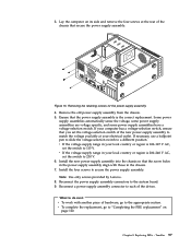
... page 126. 3. Remove the four screws at the rear of the ThinkCentre Safety and Warranty Guide, go to: http://www.lenovo.com/support This section provides instructions on how to the power supply assembly. 4. To obtain a copy of the chassis that came with your computer or attempt any repair before reading and understanding...
... page 126. 3. Remove the four screws at the rear of the ThinkCentre Safety and Warranty Guide, go to: http://www.lenovo.com/support This section provides instructions on how to the power supply assembly. 4. To obtain a copy of the chassis that came with your computer or attempt any repair before reading and understanding...


