
Service Manual
Page 1
SERVICE MANUAL MODEL : ZHD-311 LHS-25SCS/LHS-25SCW SERVICE MANUAL Product Type: DVD/CD RECEIVER Chassis: DP9 Manual Series: ZHD-311, LHS-25SCS, LHS-25SCW Manual Part #: Model Line: D Product Year: 2005 Model Series: ZHD-311 Printed in U.S.A CONTENTS GENERAL 1 AUDIO PART 2 DVD & AMP PART 3 EXPLODED VIEWS 4 SPEAKER PART 5 REPLACEMENT PARTS LIST 6 Published May 2005 by Technical Publications Zenith Electronics Corporation 201 James Record Road Huntsville, Alabama 35824-1513 Copyright © 2005 by Zenith Electronics Corporation
SERVICE MANUAL MODEL : ZHD-311 LHS-25SCS/LHS-25SCW SERVICE MANUAL Product Type: DVD/CD RECEIVER Chassis: DP9 Manual Series: ZHD-311, LHS-25SCS, LHS-25SCW Manual Part #: Model Line: D Product Year: 2005 Model Series: ZHD-311 Printed in U.S.A CONTENTS GENERAL 1 AUDIO PART 2 DVD & AMP PART 3 EXPLODED VIEWS 4 SPEAKER PART 5 REPLACEMENT PARTS LIST 6 Published May 2005 by Technical Publications Zenith Electronics Corporation 201 James Record Road Huntsville, Alabama 35824-1513 Copyright © 2005 by Zenith Electronics Corporation

Service Manual
Page 3
...is damaged. GENERAL SERVICING PRECAUTIONS NOTES REGARDING HANDLING OF THE PICK-UP 1. Also NEVER switch ON the power to enter the eyes! The lens is subjected to strong pressure or impact, the result may damage the eyes! Absolutely never permit laser beams to the laser output part (lens, etc.) ... contact fingers or other liquid cleaners, because they will damage the lens.) Take care not to use too much of precision, and for that reason the adjustment point and installation screws should never be subjected to get inside the pick-up is extremely dirty, apply isopropyl alcohol...
...is damaged. GENERAL SERVICING PRECAUTIONS NOTES REGARDING HANDLING OF THE PICK-UP 1. Also NEVER switch ON the power to enter the eyes! The lens is subjected to strong pressure or impact, the result may damage the eyes! Absolutely never permit laser beams to the laser output part (lens, etc.) ... contact fingers or other liquid cleaners, because they will damage the lens.) Take care not to use too much of precision, and for that reason the adjustment point and installation screws should never be subjected to get inside the pick-up is extremely dirty, apply isopropyl alcohol...

Service Manual
Page 4
...disc players incorporate a great many optical components and other high-precision components. Care must be grounded. 3) The workbench should be directly facing the eyes or bare skin. These components are sensitive to avoid repair...removing the laser pick-up from its conductive bag, do not place the pick-up to come in contact with clothing, in order to prevent static electricity changes..., components can be damaged, and for repair 1) Before replacing a component part, first disconnect the power supply lead wire from the pick-up (laser diode). Notes for that reason components should...
...disc players incorporate a great many optical components and other high-precision components. Care must be grounded. 3) The workbench should be directly facing the eyes or bare skin. These components are sensitive to avoid repair...removing the laser pick-up from its conductive bag, do not place the pick-up to come in contact with clothing, in order to prevent static electricity changes..., components can be damaged, and for repair 1) Before replacing a component part, first disconnect the power supply lead wire from the pick-up (laser diode). Notes for that reason components should...

Service Manual
Page 5
...be used to help reduce the incidence of typical ESD devices are integrated circuits and some field-effect transistors and semiconductor chip components. The following techniques should be removed for potential shock reasons prior to applying power to the unit under test.... lifting of a replacement ESD device, touch the protective material to install it. (Most replacement ESD devices are called Electrostatically Sensitive Devices (ESD). Do not remove a replacement ESD device from its protective package until immediately before handling any semiconductor component or semiconductor-equipped ...
...be used to help reduce the incidence of typical ESD devices are integrated circuits and some field-effect transistors and semiconductor chip components. The following techniques should be removed for potential shock reasons prior to applying power to the unit under test.... lifting of a replacement ESD device, touch the protective material to install it. (Most replacement ESD devices are called Electrostatically Sensitive Devices (ESD). Do not remove a replacement ESD device from its protective package until immediately before handling any semiconductor component or semiconductor-equipped ...

Service Manual
Page 6
... Hz 522 - 1,620 kHz or 520 - 1,720 kHz Frequency 450 kHz AMPLIFIER Surround mode (* Depending on the sound mode settings and the source, there may be no sound output.) Outputs Front: 30W + 30W (THD 10 %) Center*: 30W Surround*: 30W + 30W (6Ω at 1 kHz, THD 10 %) Subwoofer*: 70W (8Ω at 30 Hz, THD 10 %) MONITOR MIC Jacks (ø3.5mm) (KARAOKE MODEL ONLY)) SPEAKERS Type Impedance Frequency Response Sound Pressure Level Rated Input Power Max.
... Hz 522 - 1,620 kHz or 520 - 1,720 kHz Frequency 450 kHz AMPLIFIER Surround mode (* Depending on the sound mode settings and the source, there may be no sound output.) Outputs Front: 30W + 30W (THD 10 %) Center*: 30W Surround*: 30W + 30W (6Ω at 1 kHz, THD 10 %) Subwoofer*: 70W (8Ω at 30 Hz, THD 10 %) MONITOR MIC Jacks (ø3.5mm) (KARAOKE MODEL ONLY)) SPEAKERS Type Impedance Frequency Response Sound Pressure Level Rated Input Power Max.

Service Manual
Page 24
... SLED Moves to related disc reading procedure Recieve OPEN/ CLOSE Key? System operation flow Power On 1. 8082 initializes SERVO, DSP & RISC registers 2. Judge whether have disc and disc type 2. Systemoperati on Routi ne Loop 1. Reset RISC Show LOGO Yes Tray Closed? No 1. Stop Playback & Open Tray 2. SECTION 3. Execute Pressed Key & IR Key 2. DVD & AMP PART ELECTRICAL TROUBLESHOOTING GUIDE 1. Write RISC code to Closed position SLED...
... SLED Moves to related disc reading procedure Recieve OPEN/ CLOSE Key? System operation flow Power On 1. 8082 initializes SERVO, DSP & RISC registers 2. Judge whether have disc and disc type 2. Systemoperati on Routi ne Loop 1. Reset RISC Show LOGO Yes Tray Closed? No 1. Stop Playback & Open Tray 2. SECTION 3. Execute Pressed Key & IR Key 2. DVD & AMP PART ELECTRICAL TROUBLESHOOTING GUIDE 1. Write RISC code to Closed position SLED...

Service Manual
Page 25
Check systemreset circuit. 3. No (-34V,-9V,36V,5.6V ,5V,8V,9V,2.5V, 3.3V) Yes Check the POWER PART Check the POWER PART Are 3.3V and 5V DC No outputs normal on the Power PCBA Is the DC Voltage outputs OK? Test & debug flow TEST Check the AC Vol tage No Power PCBA (110V or 220V) Yes Switch on main PCBA? Check 27MHz system clock. 2. Replace FLASH( IC500) 3-2 Yes A Check the regulators or diode(D501). 1. Check FLASH Memory related circuit. Yes Update FLASH(IC500) No successfully? Check FLASH R/Wenable signal PRD, RWR. 4. 2.
Check systemreset circuit. 3. No (-34V,-9V,36V,5.6V ,5V,8V,9V,2.5V, 3.3V) Yes Check the POWER PART Check the POWER PART Are 3.3V and 5V DC No outputs normal on the Power PCBA Is the DC Voltage outputs OK? Test & debug flow TEST Check the AC Vol tage No Power PCBA (110V or 220V) Yes Switch on main PCBA? Check 27MHz system clock. 2. Replace FLASH( IC500) 3-2 Yes A Check the regulators or diode(D501). 1. Check FLASH Memory related circuit. Yes Update FLASH(IC500) No successfully? Check FLASH R/Wenable signal PRD, RWR. 4. 2.

Service Manual
Page 30
Normal PWM IC out?(IC300) Check connection between IC300 ABCK, ALRCK, ASDAT Check the related circuit of PWM.(Check Audio out Pins52, 54, 55, 59,62, 68 Check Digital Amp circuit (IC301, IC302) 3-7 E PWM IC received correct data stream?
Normal PWM IC out?(IC300) Check connection between IC300 ABCK, ALRCK, ASDAT Check the related circuit of PWM.(Check Audio out Pins52, 54, 55, 59,62, 68 Check Digital Amp circuit (IC301, IC302) 3-7 E PWM IC received correct data stream?

Service Manual
Page 31
AUDIO µ-COM Circuit(DVD & AMP) POWER ON Does CD/DVD appear NO at FLD? YES Does CD/DVD appear NO at FLD? B/D. YES YES Refer to oscillator Circuit. YES NO Check oscillator of Main NO appear at FLD? YES Check IC101 Reset Waveform. YES Check if IC101 Pin96 NO is high. Replace IC101. 3-8 YES Does no Disc... or Time NO Check power part of X101. Check if IC101 Pin32, 51, NO 80 are high(5V). YES NO Does it appear DVD Error NO at FLD? Check ...
AUDIO µ-COM Circuit(DVD & AMP) POWER ON Does CD/DVD appear NO at FLD? YES Does CD/DVD appear NO at FLD? B/D. YES YES Refer to oscillator Circuit. YES NO Check oscillator of Main NO appear at FLD? YES Check IC101 Reset Waveform. YES Check if IC101 Pin96 NO is high. Replace IC101. 3-8 YES Does no Disc... or Time NO Check power part of X101. Check if IC101 Pin32, 51, NO 80 are high(5V). YES NO Does it appear DVD Error NO at FLD? Check ...

Service Manual
Page 32
DETAILS AND WAVEFORMS ON SYSTEM TEST AND DEBUGGING 1. SYSTEM 27MHz CLOCK,RESET,FLASH R/W SIGNAL 1) ES6698FD main clock is at 27MHz(X501) 3.8V, 27MHz FIG 1-1 2) ES6698FD reset is high active. Power Cord in FIG 1-2 3-9 5.2VA PWR_CTL(SYSTEM µ-COM) IC501 PIN83) M_RESET(IC501 PIN 207) URST(IC501 PIN 188)
DETAILS AND WAVEFORMS ON SYSTEM TEST AND DEBUGGING 1. SYSTEM 27MHz CLOCK,RESET,FLASH R/W SIGNAL 1) ES6698FD main clock is at 27MHz(X501) 3.8V, 27MHz FIG 1-1 2) ES6698FD reset is high active. Power Cord in FIG 1-2 3-9 5.2VA PWR_CTL(SYSTEM µ-COM) IC501 PIN83) M_RESET(IC501 PIN 207) URST(IC501 PIN 188)
Service Manual
Page 34
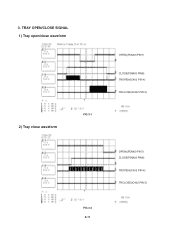
3. TRAY OPEN/CLOSE SIGNAL 1) Tray open/close waveform 2) Tray close waveform FIG 3-1 FIG 3-2 3-11 OPEN((PDM03 PIN7) CLOSE(PDM03 PIN8) TROPEN(IC402 PIN 4) TRCLOSE(IC402 PIN 5) OPEN((PDM03 PIN7) CLOSE(PDM03 PIN8) TROPEN(IC402 PIN 4) TRCLOSE(IC402 PIN 5)
3. TRAY OPEN/CLOSE SIGNAL 1) Tray open/close waveform 2) Tray close waveform FIG 3-1 FIG 3-2 3-11 OPEN((PDM03 PIN7) CLOSE(PDM03 PIN8) TROPEN(IC402 PIN 4) TRCLOSE(IC402 PIN 5) OPEN((PDM03 PIN7) CLOSE(PDM03 PIN8) TROPEN(IC402 PIN 4) TRCLOSE(IC402 PIN 5)
Service Manual
Page 35
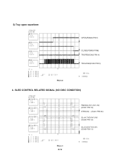
3) Tray open waveform OPEN(PDM03 PIN7) CLOSE(PDM03 PIN8) TROPEN(IC402 PIN 4) TRCLOSE(IC402 PIN 5) FIG 3-3 4. SLED CONTROL RELATED SIGNAL (NO DISC CONDITION) FMSO(2.0V/1.4V/1.0V) (IC501 PIN 19) STBY(5V) - (IC401 PIN 50) SL+(4.7V/3.6V/1.9V) (IC404 PIN 12) SL-(5.3V/3.7V/2.5V) (IC404 PIN 11) FIG 4-1 3-12
3) Tray open waveform OPEN(PDM03 PIN7) CLOSE(PDM03 PIN8) TROPEN(IC402 PIN 4) TRCLOSE(IC402 PIN 5) FIG 3-3 4. SLED CONTROL RELATED SIGNAL (NO DISC CONDITION) FMSO(2.0V/1.4V/1.0V) (IC501 PIN 19) STBY(5V) - (IC401 PIN 50) SL+(4.7V/3.6V/1.9V) (IC404 PIN 12) SL-(5.3V/3.7V/2.5V) (IC404 PIN 11) FIG 4-1 3-12
Service Manual
Page 39
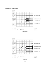
FOCUS ON WAVEFORMS FE(IC401 PIN 40) FOSO(IC501 PIN12) F+(IC404 PIN 14) F-(IC404 PIN 13) FIG 8-1 (DVD) FE(IC401 PIN 40) FOSO(IC501 PIN12) F+(IC404 PIN 14) F-(IC404 PIN 13) FIG 8-2 (CD) 3-16 8.
FOCUS ON WAVEFORMS FE(IC401 PIN 40) FOSO(IC501 PIN12) F+(IC404 PIN 14) F-(IC404 PIN 13) FIG 8-1 (DVD) FE(IC401 PIN 40) FOSO(IC501 PIN12) F+(IC404 PIN 14) F-(IC404 PIN 13) FIG 8-2 (CD) 3-16 8.

Service Manual
Page 40
SPINDLE CONTROL WAVEFORMS (NO DISC CONDITION) DMSO(1.4V/1.8V) (IC501 PIN 18) SP-(3.6V/2.4V) (IC404 PIN 18) SP+(3.6V/4.8V) (IC404 PIN 17) FIG 9-1 10. TRACKING CONTROL RELATED SIGNAL(System checking) TE(IC401 PIN 39) TRSO(IC501 PIN 13) T-(IC404 PIN 16) T+(IC404 PIN 15) FIG 10-1(DVD) 3-17 9.
SPINDLE CONTROL WAVEFORMS (NO DISC CONDITION) DMSO(1.4V/1.8V) (IC501 PIN 18) SP-(3.6V/2.4V) (IC404 PIN 18) SP+(3.6V/4.8V) (IC404 PIN 17) FIG 9-1 10. TRACKING CONTROL RELATED SIGNAL(System checking) TE(IC401 PIN 39) TRSO(IC501 PIN 13) T-(IC404 PIN 16) T+(IC404 PIN 15) FIG 10-1(DVD) 3-17 9.

Service Manual
Page 42
12. ES6698FD VIDEO OUTPUT WAVEFORMS 1) Full colorbar signal(COMPOSIT) (IC501 PIN 110) 2) Y FIG 12-1 (IC501 PIN 113) FIG 12-2 3-19
12. ES6698FD VIDEO OUTPUT WAVEFORMS 1) Full colorbar signal(COMPOSIT) (IC501 PIN 110) 2) Y FIG 12-1 (IC501 PIN 113) FIG 12-2 3-19

Service Manual
Page 43
13. AUDIO OUTPUT FROM PWM IC 1) Audio L/R (IC300 PIN 68, 49) 2) Audio related Signal FIG 13-1 ASDATA3 FIG 13-2 3-20 ASDAT0(IC501 PIN 117) ABCK(IC501 PIN 123) ALRCK(IC501 PIN 116)
13. AUDIO OUTPUT FROM PWM IC 1) Audio L/R (IC300 PIN 68, 49) 2) Audio related Signal FIG 13-1 ASDATA3 FIG 13-2 3-20 ASDAT0(IC501 PIN 117) ABCK(IC501 PIN 123) ALRCK(IC501 PIN 116)

Service Manual
Page 44
14. DVD & AMP WAVEFORMS 1) 2) • R315 → FRONT L 3) • R310 → FRONT R 4) • R316 → REAR 5) • R324 → REAR 6) • R303 → CENTER • R317 → WOOFER 3-21
14. DVD & AMP WAVEFORMS 1) 2) • R315 → FRONT L 3) • R310 → FRONT R 4) • R316 → REAR 5) • R324 → REAR 6) • R303 → CENTER • R317 → WOOFER 3-21

Service Manual
Page 50
SECTION 4. EXPLODED VIEWS • CABINET AND MAIN FRAME SECTION 463 463 463 KARAOKE OPTION 283 452 A26 274 A41 A43 452 274 A50 279 261 261 463 463 463 A47 465 261 A44 320 A46 305 OPTIONAL PART 351 463 4-1 4-2
SECTION 4. EXPLODED VIEWS • CABINET AND MAIN FRAME SECTION 463 463 463 KARAOKE OPTION 283 452 A26 274 A41 A43 452 274 A50 279 261 261 463 463 463 A47 465 261 A44 320 A46 305 OPTIONAL PART 351 463 4-1 4-2

Service Manual
Page 51
... ASSEMBLY,AUDIO CLAMP ASSEMBLY BASE ASSEMBLY BASE ASSEMBLY PLATE MAGNET CLAMP CABLE,FLAT RUBBER ...Parts SPECIFICATION HOME THEATER LH-TK750/550/250 REMARKS DISC DP7 - PART NO. SH MAIN DP-9T-ESS SLED DP-9T-DI -ESS-SAMSUNG CLAMP NSP CLAMP(LDM-R608,10*5,1*1.5T) NSP UPPER DP7 NSP P=1.0 FFC UL2896(0.035X0.7) 23 DVD DP-6, DP-8 FRONT RIGHT 20 DVD REAR...DVD PU, DR-02 SUS-420J2 OTHER + 1 D1.7 L7.0 SWCH18A/BZN DP8 + 1 D1.7 L4.5 SWCH18A/NI DP8 P + 1 D1.7 L4.5 SWRCH18A/FZY DP8 MACHINE + 1 D1.7 L10.0 SWRCH18A/FZW DP + D2.0 6MM SWRCH16A/ZNBK 4MM 1 4-4 • DECK MECHANISM EXPLODED VIEW...
... ASSEMBLY,AUDIO CLAMP ASSEMBLY BASE ASSEMBLY BASE ASSEMBLY PLATE MAGNET CLAMP CABLE,FLAT RUBBER ...Parts SPECIFICATION HOME THEATER LH-TK750/550/250 REMARKS DISC DP7 - PART NO. SH MAIN DP-9T-ESS SLED DP-9T-DI -ESS-SAMSUNG CLAMP NSP CLAMP(LDM-R608,10*5,1*1.5T) NSP UPPER DP7 NSP P=1.0 FFC UL2896(0.035X0.7) 23 DVD DP-6, DP-8 FRONT RIGHT 20 DVD REAR...DVD PU, DR-02 SUS-420J2 OTHER + 1 D1.7 L7.0 SWCH18A/BZN DP8 + 1 D1.7 L4.5 SWCH18A/NI DP8 P + 1 D1.7 L4.5 SWRCH18A/FZY DP8 MACHINE + 1 D1.7 L10.0 SWRCH18A/FZW DP + D2.0 6MM SWRCH16A/ZNBK 4MM 1 4-4 • DECK MECHANISM EXPLODED VIEW...

Service Manual
Page 53
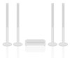
...953 954 955 956 957 958 A900 PART NO. 3720RMF085D 5208RM0056B 4766RM0097A 3701RM0060A 353M050C 6400WSMH01A 3091RMW164A 3610RM0009A 6871RU9271F 6401RM0227A DESCRIPTION PANEL,FRONT DUCT FELT NET ASSEMBLY SCREW,DRAWING SPEAKER,WOOFER CABINET ASSEMBLY FOOT PWB(PCB) ASSEMBLY,SUBSET(AUDIO SPEAKER ASSEMBLY 5-2 SPECIFICATION SPK LHS-25SCW MOLD S33-740-A32... NET ASSY STANDA BH 3.5X16 FBK CW-136B70L SAMMI WOOFER 8OHM 7 SPK LHS-25SCW WOOD CABINET ASS LXS-330, EVA(BLACK) PHI15X1T, LHS-D6230W SUB WOOFER 2.5M, OR F65C-D275L-1 TOPTONE LHS-25SCW • MODEL : LHS-25SCW A900 953 954 955 952 951 950...
...953 954 955 956 957 958 A900 PART NO. 3720RMF085D 5208RM0056B 4766RM0097A 3701RM0060A 353M050C 6400WSMH01A 3091RMW164A 3610RM0009A 6871RU9271F 6401RM0227A DESCRIPTION PANEL,FRONT DUCT FELT NET ASSEMBLY SCREW,DRAWING SPEAKER,WOOFER CABINET ASSEMBLY FOOT PWB(PCB) ASSEMBLY,SUBSET(AUDIO SPEAKER ASSEMBLY 5-2 SPECIFICATION SPK LHS-25SCW MOLD S33-740-A32... NET ASSY STANDA BH 3.5X16 FBK CW-136B70L SAMMI WOOFER 8OHM 7 SPK LHS-25SCW WOOD CABINET ASS LXS-330, EVA(BLACK) PHI15X1T, LHS-D6230W SUB WOOFER 2.5M, OR F65C-D275L-1 TOPTONE LHS-25SCW • MODEL : LHS-25SCW A900 953 954 955 952 951 950...


