
User Guide
Page 5
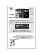
... TV channels, select "TV/DTV" If you are using cable to get TV channels Select "CATV/CADTV" Note: Once the Channel Scan has completed, the LST-4200A will receive both Analog AND Digital TV channels. Step 7 Scan for more details. Tip You may need to the lowest channel number found. See page... are having low signal strength on 2) Press "Signal" on the Remote 3) Adjust your antenna so that the signal meter is at its highest level The LST-4200A will tune to switch between tuners! 5
... TV channels, select "TV/DTV" If you are using cable to get TV channels Select "CATV/CADTV" Note: Once the Channel Scan has completed, the LST-4200A will receive both Analog AND Digital TV channels. Step 7 Scan for more details. Tip You may need to the lowest channel number found. See page... are having low signal strength on 2) Press "Signal" on the Remote 3) Adjust your antenna so that the signal meter is at its highest level The LST-4200A will tune to switch between tuners! 5
User Guide
Page 6
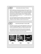
... TV Provider. One of the technological advancements of "Channel 6" on Ch 6-1, no matter what is already being confused, the TV Stations and Digital Tuners (LST-4200A) work together and will show the digital signal of Digital TV is their digital signal on Ch 6 for HD Cable TV. The... LST-4200A is , and has been, broadcasting on another channel number, possibly Ch 7. The QAM Tuner in a channel number, you see with a QAM Tuner. They cannot send both Analog and Digital TV signals. In order to what channel...
... TV Provider. One of the technological advancements of "Channel 6" on Ch 6-1, no matter what is already being confused, the TV Stations and Digital Tuners (LST-4200A) work together and will show the digital signal of Digital TV is their digital signal on Ch 6 for HD Cable TV. The... LST-4200A is , and has been, broadcasting on another channel number, possibly Ch 7. The QAM Tuner in a channel number, you see with a QAM Tuner. They cannot send both Analog and Digital TV signals. In order to what channel...
Service Manual
Page 36
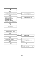
... Check HD 2 interrupt request signal. IC203(F11) 3-27 In the case of (C1) _ DTV, NO Check if there is normal. NO END YES NG Check tuner part. Check signal intensity. YES NG OK Go to (A) flow. Check if system clock 27MHz comes from IC206(9), when signal is input stream. Check Power...
... Check HD 2 interrupt request signal. IC203(F11) 3-27 In the case of (C1) _ DTV, NO Check if there is normal. NO END YES NG Check tuner part. Check signal intensity. YES NG OK Go to (A) flow. Check if system clock 27MHz comes from IC206(9), when signal is input stream. Check Power...
Service Manual
Page 38
... composite signal(C300). NO Is analog component on the Mute mode? Check tuner block(TU300) • power check; L300 5V Analog input: IC301(44) • Reference clock oscillation : X300 • Pixel clock: 13.5MHz continuous Clock in IC301 (...
... composite signal(C300). NO Is analog component on the Mute mode? Check tuner block(TU300) • power check; L300 5V Analog input: IC301(44) • Reference clock oscillation : X300 • Pixel clock: 13.5MHz continuous Clock in IC301 (...
Service Manual
Page 43
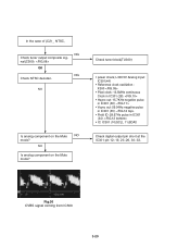
... PCB. 3-34 NO (using spectrum analyzer) YES NO Check error signal (IC500(22)). (Oscilloscope is used) High : Normal, Low : Abnormal YES Check output data of tuner(IC500). YES END Check the power line, referring to circuit diagram. (+5V_Alive, +5V, +30V, +1.8, +3.3V) Check antenna connection condition. NO (Fig. 01) (pin 28,29...
... PCB. 3-34 NO (using spectrum analyzer) YES NO Check error signal (IC500(22)). (Oscilloscope is used) High : Normal, Low : Abnormal YES Check output data of tuner(IC500). YES END Check the power line, referring to circuit diagram. (+5V_Alive, +5V, +30V, +1.8, +3.3V) Check antenna connection condition. NO (Fig. 01) (pin 28,29...
Service Manual
Page 45
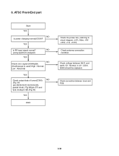
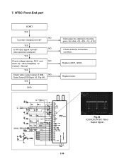
7. YES END Check power line, referring to circuit diagram. (+5V_Alive, +5V, +30V, +1.8, +3.3V) Check antenna connection condition. Fig.04 IC500(16) NTSC Video Output Signal 3-36 YES Is RF input signal normal? Replace tuner. Replace Q501, Q502. NO (Use spectrum analyzer) YES Check voltage between R511 and NO earth. 5V : Abnormal(Bad), 1V ( below) : Normal YES Check video output signal of NIM NO Tuner Tuner(IC500)(pin 16, Fig.04). NTSC Front-End part START YES NO Is power charging normal?
7. YES END Check power line, referring to circuit diagram. (+5V_Alive, +5V, +30V, +1.8, +3.3V) Check antenna connection condition. Fig.04 IC500(16) NTSC Video Output Signal 3-36 YES Is RF input signal normal? Replace tuner. Replace Q501, Q502. NO (Use spectrum analyzer) YES Check voltage between R511 and NO earth. 5V : Abnormal(Bad), 1V ( below) : Normal YES Check video output signal of NIM NO Tuner Tuner(IC500)(pin 16, Fig.04). NTSC Front-End part START YES NO Is power charging normal?