Installation Instructions
Page 2
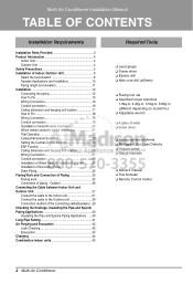
Multi Air Conditioner Installation Manual TABLE OF CONTENTS Installation Requirements Installation Parts Provided 3 Product Introduction 4 Indoor Unit 4 Outdoor Unit 4 Safety Precautions 5 Installation of Indoor, Outdoor Unit 8 Select the best location 8 Seaside Applications and Installation 10 Piping length and elevation 11 Installation 12 Connecting the piping 12 How To Fix 15 Wiring Connection 16 Conduit connection 16 Ceiling dimension...
Multi Air Conditioner Installation Manual TABLE OF CONTENTS Installation Requirements Installation Parts Provided 3 Product Introduction 4 Indoor Unit 4 Outdoor Unit 4 Safety Precautions 5 Installation of Indoor, Outdoor Unit 8 Select the best location 8 Seaside Applications and Installation 10 Piping length and elevation 11 Installation 12 Connecting the piping 12 How To Fix 15 Wiring Connection 16 Conduit connection 16 Ceiling dimension...
Installation Instructions
Page 3
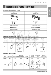
... Provided [Standard /Artcool Mirror Type] Type 1 Installation plate Type 2 Installation plate ENGLISH Type "B" screw Type "A" screw (6 EA) Remote control holder Type "B" screw Type "A" screw (8 EA) Remote control holder [Cealing Concealed Duct Type] Name Clamp metal ...(M4) 2EA Conduit Bracket 1 EA Insulation for Remote fitting control holder 1 SET 1 EA Shape Conduit Bracket for gas pipe Screw(M4) 2EA for liquid pipe Installation Manual 3
... Provided [Standard /Artcool Mirror Type] Type 1 Installation plate Type 2 Installation plate ENGLISH Type "B" screw Type "A" screw (6 EA) Remote control holder Type "B" screw Type "A" screw (8 EA) Remote control holder [Cealing Concealed Duct Type] Name Clamp metal ...(M4) 2EA Conduit Bracket 1 EA Insulation for Remote fitting control holder 1 SET 1 EA Shape Conduit Bracket for gas pipe Screw(M4) 2EA for liquid pipe Installation Manual 3
Installation Instructions
Page 5
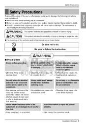
... grounding. Be sure not to properties only. Installation Manual 5 I The meanings of the symbols used in a fire or electric shock due to dust, water, etc. • Otherwise, it may cause a fire indoor unit and ... the product, always contact the service center or a professional installation agency. • Otherwise, it may cause electrical shock. • Otherwise, it may cause a fire or electrical shock. • Otherwise, it could result in this manual are not attached securely, it may cause injury or an accident. • It will cause harm or...
... grounding. Be sure not to properties only. Installation Manual 5 I The meanings of the symbols used in a fire or electric shock due to dust, water, etc. • Otherwise, it may cause a fire indoor unit and ... the product, always contact the service center or a professional installation agency. • Otherwise, it may cause electrical shock. • Otherwise, it may cause a fire or electrical shock. • Otherwise, it could result in this manual are not attached securely, it may cause injury or an accident. • It will cause harm or...
Installation Instructions
Page 7
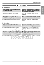
... so that drain can be securely done. • Otherwise, it may cause water leakage. Installation Manual 7 Keep level parallel in installing the product. • Otherwise, it may cause the failure of product. Do not use wax, thinner, or a strong detergent. • The ... CAUTION I Operation Avoid excessive cooling and perform ventilation sometimes. • Otherwise, it may cause the failure of appliance or an accident. I Installation Install the drain hose to ensure that the noise or hot wind from the outdoor unit may not cause any damage to the neighbors. • Otherwise...
... so that drain can be securely done. • Otherwise, it may cause water leakage. Installation Manual 7 Keep level parallel in installing the product. • Otherwise, it may cause the failure of product. Do not use wax, thinner, or a strong detergent. • The ... CAUTION I Operation Avoid excessive cooling and perform ventilation sometimes. • Otherwise, it may cause the failure of appliance or an accident. I Installation Install the drain hose to ensure that the noise or hot wind from the outdoor unit may not cause any damage to the neighbors. • Otherwise...
Installation Instructions
Page 9
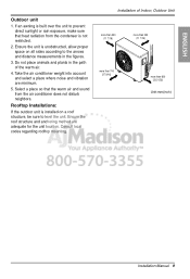
...11 7/16) more than 300 (11 7/16) more than 700 (27 9/16) more than 600 (23 21/32) Unit:mm(inch) Installation Manual 9 Rooftop Installations: If the outdoor unit is not restricted. 2. Take the air conditioner weight into account and select a place where noise and vibration are adequate... for the unit location. Installation of the warm air. 4. Do not place animals and plants in the figures. 3. Consult local codes regarding rooftop mounting. Ensure the roof...
...11 7/16) more than 300 (11 7/16) more than 700 (27 9/16) more than 600 (23 21/32) Unit:mm(inch) Installation Manual 9 Rooftop Installations: If the outdoor unit is not restricted. 2. Take the air conditioner weight into account and select a place where noise and vibration are adequate... for the unit location. Installation of the warm air. 4. Do not place animals and plants in the figures. 3. Consult local codes regarding rooftop mounting. Ensure the roof...
Installation Instructions
Page 11
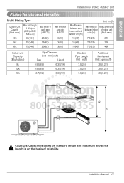
Installation Manual 11 ENGLISH Installation of Indoor, Outdoor Unit Piping length and elevation Multi Piping Type Outdoor Unit Capacity (Btu/h class) 18k Max total length of all pipes (A+B)/(A+B+C)/ (A+B+C+D) 50(164) ...
Installation Manual 11 ENGLISH Installation of Indoor, Outdoor Unit Piping length and elevation Multi Piping Type Outdoor Unit Capacity (Btu/h class) 18k Max total length of all pipes (A+B)/(A+B+C)/ (A+B+C+D) 50(164) ...
Installation Instructions
Page 13
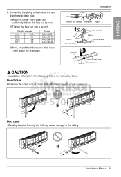
... Flare nut Pipes Wrench Indoor unit tubing Open-end wrench (fixed) Flare nut Connection pipe Drain pipe Indoor unit drain hose Adhesive Vinyl tape(narrow) Installation Information. Installation Manual 13 For left may cause damage to slowly downward. Then attach the drain pipe. Follow the instruction below. Outside diameter mm inch Ø6.35...
... Flare nut Pipes Wrench Indoor unit tubing Open-end wrench (fixed) Flare nut Connection pipe Drain pipe Indoor unit drain hose Adhesive Vinyl tape(narrow) Installation Information. Installation Manual 13 For left may cause damage to slowly downward. Then attach the drain pipe. Follow the instruction below. Outside diameter mm inch Ø6.35...

Installation Instructions
Page 15
... To Fix The wall you select should be done safely. Mount the installation plate on a concrete wall, use caution concerning the location of the installation plate-routing of the wiring to prevent vibration 1. Installation Plate Chassis Hook Type "A" 110(4 11/32) 110(4 11/32) Ø...70mm 90(3 17/32) Left rear piping 70(2 3/4) Ø70mm Right rear piping Installation Plate Chassis Hook Type "A" Ø70mm 133mm Left rear piping 100mm Ø70mm Right rear piping Installation Manual 15 Measure the wall and mark the centerline. Drilling the hole through the walls typically.
... To Fix The wall you select should be done safely. Mount the installation plate on a concrete wall, use caution concerning the location of the installation plate-routing of the wiring to prevent vibration 1. Installation Plate Chassis Hook Type "A" 110(4 11/32) 110(4 11/32) Ø...70mm 90(3 17/32) Left rear piping 70(2 3/4) Ø70mm Right rear piping Installation Plate Chassis Hook Type "A" Ø70mm 133mm Left rear piping 100mm Ø70mm Right rear piping Installation Manual 15 Measure the wall and mark the centerline. Drilling the hole through the walls typically.
Installation Instructions
Page 17
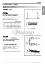
... 4 M10 SP. POSITION OF CONSOLE BOLT • A place where the unit will be leveled and that can support the weight of Unit Install the unit above the ceiling correctly. Unit:mm(inch) Dimension Capacity Btu/h class 9/12k ABCDE FGH I 850 900 383 570 93.5 190 20... unit leaning to absorb unnecessary vibration. • Apply a filter Accessory at air return hole. washer X 4 (Local supply) M10 Nut X 4 Installation Manual 17 washer X 4 (Local supply) M10 washer X 4 M10 washer X 4 M10 SP. B A CASE 1 D C E POSITION OF SUSPENSION BOLT • Apply a joint-canvas between ...
... 4 M10 SP. POSITION OF CONSOLE BOLT • A place where the unit will be leveled and that can support the weight of Unit Install the unit above the ceiling correctly. Unit:mm(inch) Dimension Capacity Btu/h class 9/12k ABCDE FGH I 850 900 383 570 93.5 190 20... unit leaning to absorb unnecessary vibration. • Apply a filter Accessory at air return hole. washer X 4 (Local supply) M10 Nut X 4 Installation Manual 17 washer X 4 (Local supply) M10 washer X 4 M10 washer X 4 M10 SP. B A CASE 1 D C E POSITION OF SUSPENSION BOLT • Apply a joint-canvas between ...
Installation Instructions
Page 19
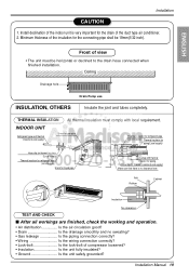
...Make sure that there is very important for the connecting pipe shall be horizontal or declined to the drain hose connected when finished installation. Front of the insulation for the drain of compressor loosened? • Insulation Is the unit fully insulated? • Ground Is...working and operation. • Air distribution Is the air circulation good? • Drain Is the drainage smoothly and no clearance here. Installation Manual 19 Install declination of the indoor unit is no sweating? • Gas leakage Is the piping connection correctly? • Wiring Is the wiring ...
...Make sure that there is very important for the connecting pipe shall be horizontal or declined to the drain hose connected when finished installation. Front of the insulation for the drain of compressor loosened? • Insulation Is the unit fully insulated? • Ground Is...working and operation. • Air distribution Is the air circulation good? • Drain Is the drainage smoothly and no clearance here. Installation Manual 19 Install declination of the indoor unit is no sweating? • Gas leakage Is the piping connection correctly? • Wiring Is the wiring ...
Installation Instructions
Page 21
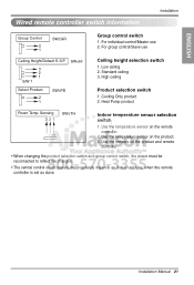
... Height/Default E.S.P 3 2 1 S/W 1 SW±HI Select Product 2 1 SW±PD Ceiling height selection switch 1. Heat Pump product Room Temp. ENGLISH Wired remote controller switch information Installation Group Control 2 1 SW±GR Group control switch 1. Installation Manual 21 Use the temperature sensor on the product. 3.
... Height/Default E.S.P 3 2 1 S/W 1 SW±HI Select Product 2 1 SW±PD Ceiling height selection switch 1. Heat Pump product Room Temp. ENGLISH Wired remote controller switch information Installation Group Control 2 1 SW±GR Group control switch 1. Installation Manual 21 Use the temperature sensor on the product. 3.
Installation Instructions
Page 23
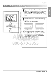
...unit as Fahrenheit. The system will automatically release without input after 30 seconds. Defrost Preheat Out door Room Temp Total on Central Run Installation Manual 23 Defrost Preheat Out door Room Temp Total on Central Run Defrost Preheat Out door Room Temp Total on Central Run 3 After setting... seconds to enter the setting Mode. 2 Press the temperature control button to exit the setting Mode. ENGLISH Celsius/Fahrenheit Switching Installation PQRCUCS0C Defrost Preheat Out door Room Temp Total on Central Run MODE TEMP FAN SPEED TEMP 1 If you want to change the unit....
...unit as Fahrenheit. The system will automatically release without input after 30 seconds. Defrost Preheat Out door Room Temp Total on Central Run Installation Manual 23 Defrost Preheat Out door Room Temp Total on Central Run Defrost Preheat Out door Room Temp Total on Central Run 3 After setting... seconds to enter the setting Mode. 2 Press the temperature control button to exit the setting Mode. ENGLISH Celsius/Fahrenheit Switching Installation PQRCUCS0C Defrost Preheat Out door Room Temp Total on Central Run MODE TEMP FAN SPEED TEMP 1 If you want to change the unit....
Installation Instructions
Page 25
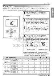
...84 94 104 114 69 77 88 99 110 90 97 105 114 122 82 90 99 109 119 75 84 93 103 114 Installation Manual 25 The value of E.S.P can be adjusted from 1 to ESP 10.) 4 Press the mode button and the temperature increasing button (L)... setting will be activated after the temperature display flashes three times. Press the fan speed button to 175 ❈ The E.S.P value is the example of installation. EX) Lo Med Static pressure(mmAq) Model name Step(H/M/L) AMNW09GB1A0 [LMDN095HV] 8.5 CMM(300cfm) 7.5 CMM(265cfm) 6.5 CMM(230cfm) AMNW12GB1A0 [LMDN125HV] 9.5 CMM(336cfm)...
...84 94 104 114 69 77 88 99 110 90 97 105 114 122 82 90 99 109 119 75 84 93 103 114 Installation Manual 25 The value of E.S.P can be adjusted from 1 to ESP 10.) 4 Press the mode button and the temperature increasing button (L)... setting will be activated after the temperature display flashes three times. Press the fan speed button to 175 ❈ The E.S.P value is the example of installation. EX) Lo Med Static pressure(mmAq) Model name Step(H/M/L) AMNW09GB1A0 [LMDN095HV] 8.5 CMM(300cfm) 7.5 CMM(265cfm) 6.5 CMM(230cfm) AMNW12GB1A0 [LMDN125HV] 9.5 CMM(336cfm)...
Installation Instructions
Page 27
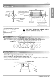
Conduit bracket Connecting Cable Screw Conduit Installation Manual 27 Hanging Bolt - M10 Plate Washer - Wiring Connection • Open the control box cover and connect the remote control cord and indoor power wires. W 3/8 or ... (accessory) Nut (W3/8 or M10) Keep the length of 15~18mm(5/8~3/4 inch) between the air conditioner bottom surface and the ceiling surface Paper model for installation Set screw of paper model (4 pieces) Open the ceiling board along the outer edge of the paper model • The following parts are local purchasing...
Conduit bracket Connecting Cable Screw Conduit Installation Manual 27 Hanging Bolt - M10 Plate Washer - Wiring Connection • Open the control box cover and connect the remote control cord and indoor power wires. W 3/8 or ... (accessory) Nut (W3/8 or M10) Keep the length of 15~18mm(5/8~3/4 inch) between the air conditioner bottom surface and the ceiling surface Paper model for installation Set screw of paper model (4 pieces) Open the ceiling board along the outer edge of the paper model • The following parts are local purchasing...
Installation Instructions
Page 29
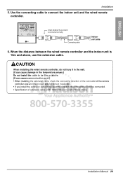
Installation Manual 29 When the distance between the wired remote controller and the indoor unit is connected correctly. Connecting cable Indoor unit side 6. Use the connecting cable to be 50m or above. (It can cause communication error.) • When installing the extension cable, check... the connecting direction of the connector of the remote controller side and the product side for correct installation. • If you install the extension cable in the opposite direction, the connector will not be connected. • Specification of extension cable: 2547 ...
Installation Manual 29 When the distance between the wired remote controller and the indoor unit is connected correctly. Connecting cable Indoor unit side 6. Use the connecting cable to be 50m or above. (It can cause communication error.) • When installing the extension cable, check... the connecting direction of the connector of the remote controller side and the product side for correct installation. • If you install the extension cable in the opposite direction, the connector will not be connected. • Specification of extension cable: 2547 ...
Installation Instructions
Page 31
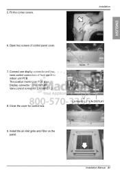
Connect one display connector and two vane control connectors of control panel cover. 7. The position marking on the panel. 5. Fit the corner covers. Close the cover for control box. Installation ENGLISH 6. Open two screws of front panel to indoor unit PCB. Installation Manual 31 Install the air inlet grille and Filter on PCB is as: Display connector : CN-DISPLAY Vane control connector: CN-VANE 1,2 8. Screw CN-VANE 1,2 CN-DISPLAY 9.
Connect one display connector and two vane control connectors of control panel cover. 7. The position marking on the panel. 5. Fit the corner covers. Close the cover for control box. Installation ENGLISH 6. Open two screws of front panel to indoor unit PCB. Installation Manual 31 Install the air inlet grille and Filter on PCB is as: Display connector : CN-DISPLAY Vane control connector: CN-VANE 1,2 8. Screw CN-VANE 1,2 CN-DISPLAY 9.
Installation Instructions
Page 33
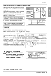
... screwed hose may cause a leakage of the drain connection on the indoor unit is complete, connect the flexible drain hose to drain water. Installation Upward routing not allowed 1/50~1/100 MAX : 700 mm(27 9/16 inch) Flexible drain hose (accessory) Main drain pipe Drain port Glue...port on the indoor unit. • The outside diameter of water. Heat insulation material: Polyethylene foam with thickness more than 8mm(5/16 inch). Installation Manual 33 ENGLISH [Cealing Concealed Duct/Cealing Cassette Type] • Drain piping must have down-slope (1/50 to 1/100): be sure not to ...
... screwed hose may cause a leakage of the drain connection on the indoor unit is complete, connect the flexible drain hose to drain water. Installation Upward routing not allowed 1/50~1/100 MAX : 700 mm(27 9/16 inch) Flexible drain hose (accessory) Main drain pipe Drain port Glue...port on the indoor unit. • The outside diameter of water. Heat insulation material: Polyethylene foam with thickness more than 8mm(5/16 inch). Installation Manual 33 ENGLISH [Cealing Concealed Duct/Cealing Cassette Type] • Drain piping must have down-slope (1/50 to 1/100): be sure not to ...

Installation Instructions
Page 35
... Flare nut Copper tube Bar Bar "A" Handle Yoke Cone Copper pipe Clamp handle Red arrow mark Smooth all round Inclined Surface Cracked Uneven damaged thickness Installation Manual 35 I Measure the distance between the indoor and the outdoor unit. Outside diameter A mm Ø6.35 Ø9.52 Ø12.7 inch mm inch 1/4 1.1~1.3 0.04~0.05...
... Flare nut Copper tube Bar Bar "A" Handle Yoke Cone Copper pipe Clamp handle Red arrow mark Smooth all round Inclined Surface Cracked Uneven damaged thickness Installation Manual 35 I Measure the distance between the indoor and the outdoor unit. Outside diameter A mm Ø6.35 Ø9.52 Ø12.7 inch mm inch 1/4 1.1~1.3 0.04~0.05...
Installation Instructions
Page 37
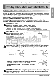
When installing, refer to the electrical diagram behind the front panel of the outdoor unit and the terminal No. RECOMMENDATION: The power cord connected to the outdoor ... be comply with the following specifications: ETL recognized and CSA certified. The wiring for the outdoor unit can not be longer than the common wires. Installation Manual 37 RECOMMENDATION: Provide a circuit breaker between Indoor Unit and Outdoor Unit Connect the cable to the Indoor unit. Outdoor Unit Capacity Power source (Btu/h class...
When installing, refer to the electrical diagram behind the front panel of the outdoor unit and the terminal No. RECOMMENDATION: The power cord connected to the outdoor ... be comply with the following specifications: ETL recognized and CSA certified. The wiring for the outdoor unit can not be longer than the common wires. Installation Manual 37 RECOMMENDATION: Provide a circuit breaker between Indoor Unit and Outdoor Unit Connect the cable to the Indoor unit. Outdoor Unit Capacity Power source (Btu/h class...
Installation Instructions
Page 39
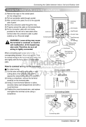
... terminal plate. Power supply cable Strand wire Round terminal Strip 10 mm(3/8") Connecting Cable Loosening the terminal block screw Fastening the wire tightly Connecting cable Installation Manual 39 A fire hazard may cause the terminal to overheat or result in unit malfunction. ENGLISH Connecting the Cable between Indoor Unit and Outdoor Unit Connection...
... terminal plate. Power supply cable Strand wire Round terminal Strip 10 mm(3/8") Connecting Cable Loosening the terminal block screw Fastening the wire tightly Connecting cable Installation Manual 39 A fire hazard may cause the terminal to overheat or result in unit malfunction. ENGLISH Connecting the Cable between Indoor Unit and Outdoor Unit Connection...


