Installation Instructions
Page 2
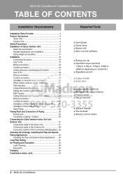
... 37 Connect the cable to the Indoor unit 37 Connect the cable to Fix 18 Wiring Connection 18 Conduit connection 18 Installation of wired Remote Controller 20 Wired remote controller switch information 21 Trial Operation 22 Celsius/Fahrenheit Switching 23 Setting the Central... Address 24 ESP Function 25 Ceiling dimension and hanging bolt location 26 Wiring Connection 27 Conduit connection 27 Installation of Wired Remote Controller(Optional)...........28 Installation of Decorative Panel 30 Drain Piping 32 Flaring Work and Connection of Piping 35 Flaring work 35 Connection ...
... 37 Connect the cable to the Indoor unit 37 Connect the cable to Fix 18 Wiring Connection 18 Conduit connection 18 Installation of wired Remote Controller 20 Wired remote controller switch information 21 Trial Operation 22 Celsius/Fahrenheit Switching 23 Setting the Central... Address 24 ESP Function 25 Ceiling dimension and hanging bolt location 26 Wiring Connection 27 Conduit connection 27 Installation of Wired Remote Controller(Optional)...........28 Installation of Decorative Panel 30 Drain Piping 32 Flaring Work and Connection of Piping 35 Flaring work 35 Connection ...
Installation Instructions
Page 3
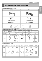
... Provided [Standard /Artcool Mirror Type] Type 1 Installation plate Type 2 Installation plate ENGLISH Type "B" screw Type "A" screw (6 EA) Remote control holder Type "B" screw Type "A" screw (8 EA) Remote control holder [Cealing Concealed Duct Type] Name Clamp metal ...(M4) 2EA Conduit Bracket 1 EA Insulation for Remote fitting control holder 1 SET 1 EA Shape Conduit Bracket for gas pipe Screw(M4) 2EA for liquid pipe Installation Manual 3
... Provided [Standard /Artcool Mirror Type] Type 1 Installation plate Type 2 Installation plate ENGLISH Type "B" screw Type "A" screw (6 EA) Remote control holder Type "B" screw Type "A" screw (8 EA) Remote control holder [Cealing Concealed Duct Type] Name Clamp metal ...(M4) 2EA Conduit Bracket 1 EA Insulation for Remote fitting control holder 1 SET 1 EA Shape Conduit Bracket for gas pipe Screw(M4) 2EA for liquid pipe Installation Manual 3
Installation Instructions
Page 5
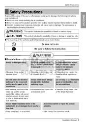
...cause a fire, electrical shock, explosion or injury. I The meanings of the symbols used in a fire or electric shock due to read before installing the air conditioner. I Incorrect operation due to properties only. Don't use flammable gases or combustibles near the air conditioner. • If the ...electrical part cover of the • No installation may cause injury or an accident. • It will cause harm or damage. Do not disassemble or repair the product randomly. •...
...cause a fire, electrical shock, explosion or injury. I The meanings of the symbols used in a fire or electric shock due to read before installing the air conditioner. I Incorrect operation due to properties only. Don't use flammable gases or combustibles near the air conditioner. • If the ...electrical part cover of the • No installation may cause injury or an accident. • It will cause harm or damage. Do not disassemble or repair the product randomly. •...
Installation Instructions
Page 6
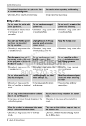
Use caution when unpacking and installing. • Sharp edges may not be seriously injured due to run into water, always contact the service center. • Otherwise, it may cause electric shock ... shock. shock and failure. Take care so that the power cord may cause injury. Do not use the damaged other appliances. Safety Precautions Do not install the product at a place that there is submerged into electrical parts. Do not modify or extend the power cord randomly. • It will cause an...
Use caution when unpacking and installing. • Sharp edges may not be seriously injured due to run into water, always contact the service center. • Otherwise, it may cause electric shock ... shock. shock and failure. Take care so that the power cord may cause injury. Do not use the damaged other appliances. Safety Precautions Do not install the product at a place that there is submerged into electrical parts. Do not modify or extend the power cord randomly. • It will cause an...
Installation Instructions
Page 7
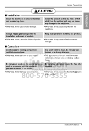
...not cause any damage to clean. Do not use an appliance for special purposes such as preserving animals vegetables, precision machine, or art articles. Install the product so that drain can be securely done. • Otherwise, it may do harm to your properties. • Otherwise, it ... with the neighbors. Do not place obstacles around the flow inlet or outlet. • Otherwise, it may cause water leakage. Keep level parallel in installing the product. • Otherwise, it may cause the failure of appliance or an accident. Do not use wax, thinner, or a strong detergent....
...not cause any damage to clean. Do not use an appliance for special purposes such as preserving animals vegetables, precision machine, or art articles. Install the product so that drain can be securely done. • Otherwise, it may do harm to your properties. • Otherwise, it ... with the neighbors. Do not place obstacles around the flow inlet or outlet. • Otherwise, it may cause water leakage. Keep level parallel in installing the product. • Otherwise, it may cause the failure of appliance or an accident. Do not use wax, thinner, or a strong detergent....
Installation Instructions
Page 8
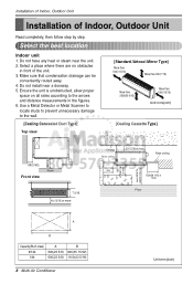
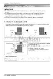
Do not have any heat or steam near a doorway. 5. Select a place where there are no obstacles in the figures. 6. Do not install near the unit. 2. Ensure the unit is unobstructed, allow proper space on all sides according to the wall. [Cealing Concealed Duct Type] Top view [Standard /..., Outdoor Unit Read completely, then follow step by step. Select the best location Indoor unit 1. Make sure that condensation drainage can be conveniently routed away. 4. Installation of Indoor, Outdoor Unit Installation of the unit. 3.
Do not have any heat or steam near a doorway. 5. Select a place where there are no obstacles in the figures. 6. Do not install near the unit. 2. Ensure the unit is unobstructed, allow proper space on all sides according to the wall. [Cealing Concealed Duct Type] Top view [Standard /..., Outdoor Unit Read completely, then follow step by step. Select the best location Indoor unit 1. Make sure that condensation drainage can be conveniently routed away. 4. Installation of Indoor, Outdoor Unit Installation of the unit. 3.
Installation Instructions
Page 9
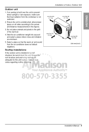
...2. Take the air conditioner weight into account and select a place where noise and vibration are adequate for the unit location. Ensure the unit is installed on all sides according to the arrows and distance measurements in the path of Indoor, Outdoor Unit more than 300 (11 7/16) more than... 300 (11 7/16) more than 700 (27 9/16) more than 600 (23 21/32) Unit:mm(inch) Installation Manual 9 Installation of the warm air. 4. Select a place so that heat radiation from the air conditioner does not disturb neighbors. Ensure the roof structure and anchoring ...
...2. Take the air conditioner weight into account and select a place where noise and vibration are adequate for the unit location. Ensure the unit is installed on all sides according to the arrows and distance measurements in the path of Indoor, Outdoor Unit more than 300 (11 7/16) more than... 300 (11 7/16) more than 700 (27 9/16) more than 600 (23 21/32) Unit:mm(inch) Installation Manual 9 Installation of the warm air. 4. Select a place so that heat radiation from the air conditioner does not disturb neighbors. Ensure the roof structure and anchoring ...
Installation Instructions
Page 10
... opposite side of space between outdoor unit and the windbreak for easy air flow. 3) Select a well-drained place. Install the outdoor unit on the product. Sea wind Sea wind 2) In case, to install the outdoor unit on the condenser and evaporator fins, could be exposed to the sea wind. 1. If outdoor unit... is installed close to the seaside, direct exposure to obstruct the wind from the sea. • The height and width should avoid direct exposure to sea wind (...
... opposite side of space between outdoor unit and the windbreak for easy air flow. 3) Select a well-drained place. Install the outdoor unit on the product. Sea wind Sea wind 2) In case, to install the outdoor unit on the condenser and evaporator fins, could be exposed to the sea wind. 1. If outdoor unit... is installed close to the seaside, direct exposure to obstruct the wind from the sea. • The height and width should avoid direct exposure to sea wind (...
Installation Instructions
Page 11
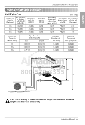
Installation Manual 11 ENGLISH Installation of Indoor, Outdoor Unit Piping length and elevation Multi Piping Type Outdoor Unit Capacity (Btu/h class) 18k Max total length of all pipes (A+B)/(A+B+C)/ (A+B+C+D) 50(164) ...
Installation Manual 11 ENGLISH Installation of Indoor, Outdoor Unit Piping length and elevation Multi Piping Type Outdoor Unit Capacity (Btu/h class) 18k Max total length of all pipes (A+B)/(A+B+C)/ (A+B+C+D) 50(164) ...
Installation Instructions
Page 12
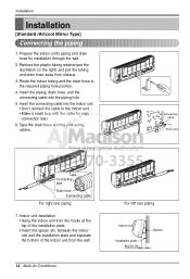
... Spacer Tape the drain hose and the connecting cables. Indoor unit installation • Hang the indoor unit from chassis. 3. between the indoor unit and the installation plate and separate the bottom of the installation plate. • Insert the spacer etc. Insert the piping, ...the drain hose to the indoor unit. • Make a small loop with the cable for installation through the wall. 2. Insert the connecting cable into the piping hole. 5. Installation Installation [Standard /Artcool Mirror Type] Connecting the piping 1. Connecting cable Drain pipe Tape Connecting pipe ...
... Spacer Tape the drain hose and the connecting cables. Indoor unit installation • Hang the indoor unit from chassis. 3. between the indoor unit and the installation plate and separate the bottom of the installation plate. • Insert the spacer etc. Insert the piping, ...the drain hose to the indoor unit. • Make a small loop with the cable for installation through the wall. 2. Insert the connecting cable into the piping hole. 5. Installation Installation [Standard /Artcool Mirror Type] Connecting the piping 1. Connecting cable Drain pipe Tape Connecting pipe ...
Installation Instructions
Page 13
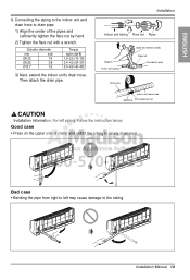
... to drain pipe. 1) Align the center of clamp and unfold the tubing to the tubing. For left may cause damage to slowly downward. Installation Manual 13 ENGLISH 8. Installation Indoor unit tubing Flare nut Pipes Wrench Indoor unit tubing Open-end wrench (fixed) Flare nut Connection pipe Drain pipe Indoor unit drain hose...
... to drain pipe. 1) Align the center of clamp and unfold the tubing to the tubing. For left may cause damage to slowly downward. Installation Manual 13 ENGLISH 8. Installation Indoor unit tubing Flare nut Pipes Wrench Indoor unit tubing Open-end wrench (fixed) Flare nut Connection pipe Drain pipe Indoor unit drain hose...
Installation Instructions
Page 14
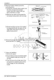
...and right sides of the chassis. 11. Reroute the pipings and the drain hose across the back of the unit against the installation plate until the hooks engage into the rear piping housing section. Piping for passage through piping hole Connecting cable Drain hose 14 ...Conditioner Wrap the insulation material around the connecting portion. 1) Overlap the connection pipe insulation and the indoor unit pipe heat insulation material. Indoor unit installation 1) Remove the spacer. 2) Ensure that there is no gap. 2) Wrap the area which they fit into their slots(clicking sound). Bind...
...and right sides of the chassis. 11. Reroute the pipings and the drain hose across the back of the unit against the installation plate until the hooks engage into the rear piping housing section. Piping for passage through piping hole Connecting cable Drain hose 14 ...Conditioner Wrap the insulation material around the connecting portion. 1) Overlap the connection pipe insulation and the indoor unit pipe heat insulation material. Indoor unit installation 1) Remove the spacer. 2) Ensure that there is no gap. 2) Wrap the area which they fit into their slots(clicking sound). Bind...

Installation Instructions
Page 15
...The wall you select should be done safely. Measure the wall and mark the centerline. Mount the installation plate on a concrete wall, use caution concerning the location of the installation plate-routing of the wiring to power outlets is also important to prevent vibration 1. If mounting ...;70mm 90(3 17/32) Left rear piping 70(2 3/4) Ø70mm Right rear piping Installation Plate Chassis Hook Type "A" Ø70mm 133mm Left rear piping 100mm Ø70mm Right rear piping Installation Manual 15 It is through the wall for piping connections must be strong and solid enough ...
...The wall you select should be done safely. Measure the wall and mark the centerline. Mount the installation plate on a concrete wall, use caution concerning the location of the installation plate-routing of the wiring to power outlets is also important to prevent vibration 1. If mounting ...;70mm 90(3 17/32) Left rear piping 70(2 3/4) Ø70mm Right rear piping Installation Plate Chassis Hook Type "A" Ø70mm 133mm Left rear piping 100mm Ø70mm Right rear piping Installation Manual 15 It is through the wall for piping connections must be strong and solid enough ...
Installation Instructions
Page 16
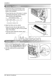
... control board individually according to Outdoor Unit 2. Set the connecting cable into place. Connecting cable Conduit connection 1. Join the conduit and the conduit bracket together. Installation Wiring Connection 1. Connect the wires to the terminals on the top inside edge of the chassis. • Press the Grille toward the chassis until it...
... control board individually according to Outdoor Unit 2. Set the connecting cable into place. Connecting cable Conduit connection 1. Join the conduit and the conduit bracket together. Installation Wiring Connection 1. Connect the wires to the terminals on the top inside edge of the chassis. • Press the Grille toward the chassis until it...
Installation Instructions
Page 17
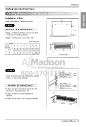
...unit. • A place where the unit can withstand its vibration. • A place where service can be leveled and that can support the weight of Unit Install the unit above the ceiling correctly. M10 Nut X 4 M10 SP. washer X 4 (Local supply) M10 washer X 4 M10 washer X 4 M10 SP.... 1/2) (46 1/2) (15 3/32) (22 7/16) (3 11/16) (7 1/2) (13/16) (41 15/16) (6 13/32) G 1/100 H Drainage hole F I CASE 2 • Install the unit leaning to absorb unnecessary vibration. • Apply a filter Accessory at air return hole. POSITION OF CONSOLE BOLT • A place where the unit will...
...unit. • A place where the unit can withstand its vibration. • A place where service can be leveled and that can support the weight of Unit Install the unit above the ceiling correctly. M10 Nut X 4 M10 SP. washer X 4 (Local supply) M10 washer X 4 M10 washer X 4 M10 SP.... 1/2) (46 1/2) (15 3/32) (22 7/16) (3 11/16) (7 1/2) (13/16) (41 15/16) (6 13/32) G 1/100 H Drainage hole F I CASE 2 • Install the unit leaning to absorb unnecessary vibration. • Apply a filter Accessory at air return hole. POSITION OF CONSOLE BOLT • A place where the unit will...
Installation Instructions
Page 18
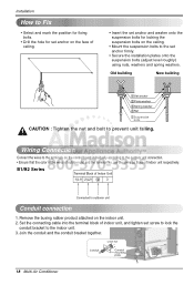
...outdooor unit Conduit connection 1. Set the connecting cable into the terminal block of indoor unit, and tighten set anchor firmly. • Secure the installation plates onto the suspension bolts (adjust level roughly) using nuts, washers and spring washers. B1/B2 Series Terminal Block of indoor unit respectively. ... Ensure that the color of the wires of outdoor unit and the terminal No. Lock nut Conduit Conduit mounting plate 18 Multi Air Conditioner Installation How to Fix • Select and mark the position for fixing bolts. • Drill the hole for set anchor on the face ...
...outdooor unit Conduit connection 1. Set the connecting cable into the terminal block of indoor unit, and tighten set anchor firmly. • Secure the installation plates onto the suspension bolts (adjust level roughly) using nuts, washers and spring washers. B1/B2 Series Terminal Block of indoor unit respectively. ... Ensure that the color of the wires of outdoor unit and the terminal No. Lock nut Conduit Conduit mounting plate 18 Multi Air Conditioner Installation How to Fix • Select and mark the position for fixing bolts. • Drill the hole for set anchor on the face ...
Installation Instructions
Page 19
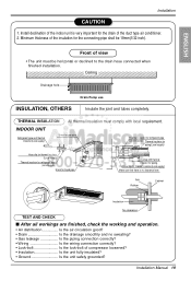
... here. Front of the insulation for the connecting pipe shall be horizontal or declined to the drain hose connected when finished installation. Hose clip for the drain of compressor loosened? • Insulation Is the unit fully insulated? • Ground Is the... Minimum thickness of view • The unit must comply with thermal insulator for liquid pipe Overlap with local requirement. Installation Manual 19 ENGLISH Installation CAUTION 1. THERMAL INSULATION All thermal insulation must be 19mm(1/32 inch). INDOOR UNIT Refrigerant pipe and thermal insulator(Local...
... here. Front of the insulation for the connecting pipe shall be horizontal or declined to the drain hose connected when finished installation. Hose clip for the drain of compressor loosened? • Insulation Is the unit fully insulated? • Ground Is the... Minimum thickness of view • The unit must comply with thermal insulator for liquid pipe Overlap with local requirement. Installation Manual 19 ENGLISH Installation CAUTION 1. THERMAL INSULATION All thermal insulation must be 19mm(1/32 inch). INDOOR UNIT Refrigerant pipe and thermal insulator(Local...
Installation Instructions
Page 20
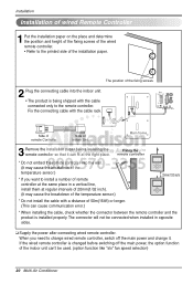
... the remote controller into the indoor unit. • The product is being shipped with the cable connected only to the printed side of the installation paper. When you want to change wired remote controller, switch off the main power, the option function of the indoor unit can fit at...of the fixing screws 2 Plug the connecting cable into the wall. (It may cause the breakdown of the temperature sensor.) * If you need to install a number of remote controller at the same place in opposite sides. ❏ Supply the power after connecting wired remote controller. The connector will not ...
... the remote controller into the indoor unit. • The product is being shipped with the cable connected only to the printed side of the installation paper. When you want to change wired remote controller, switch off the main power, the option function of the indoor unit can fit at...of the fixing screws 2 Plug the connecting cable into the wall. (It may cause the breakdown of the temperature sensor.) * If you need to install a number of remote controller at the same place in opposite sides. ❏ Supply the power after connecting wired remote controller. The connector will not ...
Installation Instructions
Page 21
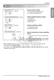
... the changes. • The central control could operate inappropriately depends on the product. 3. For group control/Slave use 2. Installation Manual 21 Use the temperature sensor on indoor unit type, when the remote controller is set as slave. ENGLISH Wired remote controller switch... information Installation Group Control 2 1 SW±GR Group control switch 1. For individual control/Master use Ceiling Height/Default E.S.P 3 2 1 S/W 1 SW±HI...
... the changes. • The central control could operate inappropriately depends on the product. 3. For group control/Slave use 2. Installation Manual 21 Use the temperature sensor on indoor unit type, when the remote controller is set as slave. ENGLISH Wired remote controller switch... information Installation Group Control 2 1 SW±GR Group control switch 1. For individual control/Master use Ceiling Height/Default E.S.P 3 2 1 S/W 1 SW±HI...
Installation Instructions
Page 22
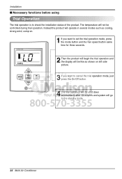
... the product will not be shut down automatically after 18 minutes and system will go to check the installation status of the product. The temperature will operate in several modes such as shown on . Installation I Necessary functions before using Trial Operation The trial operation is to the standby mode. 22 Multi Air...
... the product will not be shut down automatically after 18 minutes and system will go to check the installation status of the product. The temperature will operate in several modes such as shown on . Installation I Necessary functions before using Trial Operation The trial operation is to the standby mode. 22 Multi Air...


