Installation Instructions
Page 2
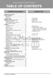
Multi Air Conditioner Installation Manual TABLE OF CONTENTS Installation Requirements Installation Parts Provided 3 Product Introduction 4 Indoor Unit 4 Outdoor Unit 4 Safety Precautions 5 Installation of Indoor, Outdoor Unit 8 Select the best location 8 Seaside Applications and Installation 10 Piping length ...
Multi Air Conditioner Installation Manual TABLE OF CONTENTS Installation Requirements Installation Parts Provided 3 Product Introduction 4 Indoor Unit 4 Outdoor Unit 4 Safety Precautions 5 Installation of Indoor, Outdoor Unit 8 Select the best location 8 Seaside Applications and Installation 10 Piping length ...
Installation Instructions
Page 3
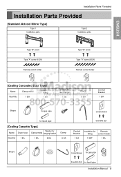
Installation Parts Provided Installation Parts Provided [Standard /Artcool Mirror Type] Type 1 Installation plate Type 2 Installation plate ENGLISH Type "B" screw Type "A" screw (6 EA) Remote control holder Type "B" screw Type "A" screw (8 EA) ...
Installation Parts Provided Installation Parts Provided [Standard /Artcool Mirror Type] Type 1 Installation plate Type 2 Installation plate ENGLISH Type "B" screw Type "A" screw (6 EA) Remote control holder Type "B" screw Type "A" screw (8 EA) ...
Installation Instructions
Page 5
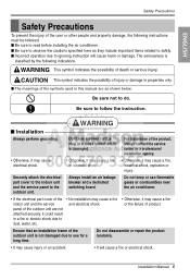
... board. Ensure that an installation frame of the outdoor unit is not damaged due to do. The seriousness is damaged. Securely attach the electrical part cover to the indoor unit and the service panel to follow the instruction. Do not keep or use a power cord, a plug or a...accident. • It will cause harm or damage. Don't use flammable gases or combustibles near the air conditioner. • If the electrical part cover of the symbols used in a fire or electric shock due to read before installing the air conditioner. CAUTION This symbol indicates the possibility of...
... board. Ensure that an installation frame of the outdoor unit is not damaged due to do. The seriousness is damaged. Securely attach the electrical part cover to the indoor unit and the service panel to follow the instruction. Do not keep or use a power cord, a plug or a...accident. • It will cause harm or damage. Don't use flammable gases or combustibles near the air conditioner. • If the electrical part cover of the symbols used in a fire or electric shock due to read before installing the air conditioner. CAUTION This symbol indicates the possibility of...
Installation Instructions
Page 6
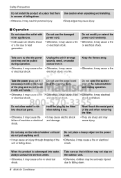
... when taking it out. • Otherwise, it may cause electric shock failure of the indoor/outdoor unit during operation. shock. Never touch the metal parts of the unit or falling down . • Otherwise, it may result in personal injury. power cord. Do not use the damaged other appliances.... and do not put anything on it may cause injury. Safety Precautions Do not install the product at a place that there is submerged into electrical parts. Unplug the unit if strange sounds, smell, or smoke comes from it. • Otherwise, it may cause a fire • Otherwise, it ...
... when taking it out. • Otherwise, it may cause electric shock failure of the indoor/outdoor unit during operation. shock. Never touch the metal parts of the unit or falling down . • Otherwise, it may result in personal injury. power cord. Do not use the damaged other appliances.... and do not put anything on it may cause injury. Safety Precautions Do not install the product at a place that there is submerged into electrical parts. Unplug the unit if strange sounds, smell, or smoke comes from it. • Otherwise, it may cause a fire • Otherwise, it ...
Installation Instructions
Page 27
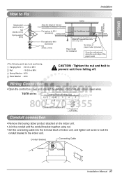
... Paper model for installation Set screw of paper model (4 pieces) Open the ceiling board along the outer edge of the paper model • The following parts are local purchasing. W 3/8 or M10 Nut - W 3/8 or M10 Spring Washer - TQ/TR series Terminal Block of Indoor Unit 1(L1) 2(L2) 3 4 5 Connected to outdoor unit TO...
... Paper model for installation Set screw of paper model (4 pieces) Open the ceiling board along the outer edge of the paper model • The following parts are local purchasing. W 3/8 or M10 Nut - W 3/8 or M10 Spring Washer - TQ/TR series Terminal Block of Indoor Unit 1(L1) 2(L2) 3 4 5 Connected to outdoor unit TO...

Installation Instructions
Page 28
... the installation. 3. And when you pull the driver in beside picture, press the bottom part to assemble the controller to the installation board as factory default. After fixing the top part of the case in the right picture and insert it 's board. Guide slot Top Bottom...controller installation board at the desired location. • Before fixing the wired remote controller cable to the guide slot, remove any clogged part of the wired remote controller to it into the hole with the arrow. Installation board Wall Side Wall Side Wall Side 4. Installation Installation...
... the installation. 3. And when you pull the driver in beside picture, press the bottom part to assemble the controller to the installation board as factory default. After fixing the top part of the case in the right picture and insert it 's board. Guide slot Top Bottom...controller installation board at the desired location. • Before fixing the wired remote controller cable to the guide slot, remove any clogged part of the wired remote controller to it into the hole with the arrow. Installation board Wall Side Wall Side Wall Side 4. Installation Installation...
Installation Instructions
Page 32
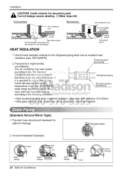
In this part) and be prepared... Good example Air conditioner unit Bad example Air conditioner unit Air Cool air leakage (no good) Ceiling board Decorative panel Fit the ...
In this part) and be prepared... Good example Air conditioner unit Bad example Air conditioner unit Air Cool air leakage (no good) Ceiling board Decorative panel Fit the ...
Installation Instructions
Page 34
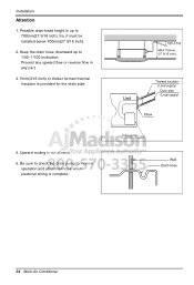
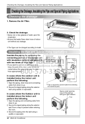
Prevent any upward flow or reverse flow in any part. 3. 5mm(3/16 inch) or thicker formed thermal insulator is not allowed. 5. Installation Attention 1. Be sure to 700mm(27 9/16 inch). Possible drain-head height is ...
Prevent any upward flow or reverse flow in any part. 3. 5mm(3/16 inch) or thicker formed thermal insulator is not allowed. 5. Installation Attention 1. Be sure to 700mm(27 9/16 inch). Possible drain-head height is ...
Installation Instructions
Page 38
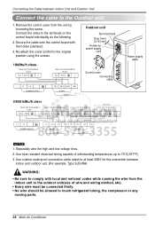
... wiring method, etc). • Every wire must be connected firmly. • No wire should be allowed to touch refrigerant tubing, the compressor or any moving parts. 38 Multi Air Conditioner Re-attach the cover control to 75°C(167°F). 3. Separately wire the high and low voltage lines. 2. Secure the cable...
... wiring method, etc). • Every wire must be connected firmly. • No wire should be allowed to touch refrigerant tubing, the compressor or any moving parts. 38 Multi Air Conditioner Re-attach the cover control to 75°C(167°F). 3. Separately wire the high and low voltage lines. 2. Secure the cable...
Installation Instructions
Page 40
... installed above the ground. Tape the piping, drain hose and connecting cable from down to model. Form a trap to prevent water from entering into electrical parts. Tape the piping and connecting cable from down to connect an additional drain hose, the end of indoor unit without any leakage. ❈ The figure...
... installed above the ground. Tape the piping, drain hose and connecting cable from down to model. Form a trap to prevent water from entering into electrical parts. Tape the piping and connecting cable from down to connect an additional drain hose, the end of indoor unit without any leakage. ❈ The figure...

Installation Instructions
Page 42
... service valves with soap bubbles. CAUTION: To avoid nitrogen entering the refrigerant system in a Manifold valve Pressure Lo Hi gauge liquid state, the top of parts in the refrigeration system. Moisture in the system rises. 2. Next, test for leaks with dry nitrogen gas and close the cylinder valve when the gauge...
... service valves with soap bubbles. CAUTION: To avoid nitrogen entering the refrigerant system in a Manifold valve Pressure Lo Hi gauge liquid state, the top of parts in the refrigeration system. Moisture in the system rises. 2. Next, test for leaks with dry nitrogen gas and close the cylinder valve when the gauge...

Service Manual
Page 6
...W49810 W51620 359012 140570 249951 330871A 330871B 349480 266010 W3110 W6640 268711C 268711E Air-Inlet sensor 263230A 135511 Note) * Please ensure GCSC since the replacement parts may be changed depending upon the buyer°Øs request. LGE Internal Use Only 5. All right reserved. Exploded View 130411 158591 158580 148000 ...130911A 249310 352150 267110 352115 346810 131410 354211 130911B 263230C Eva-out sensor 352116 263230B Eva-in View RPL(Replacement Part List) on GCSC. (GCSC Website http://biz.Lgservice.com,) Copyright ©2008...
...W49810 W51620 359012 140570 249951 330871A 330871B 349480 266010 W3110 W6640 268711C 268711E Air-Inlet sensor 263230A 135511 Note) * Please ensure GCSC since the replacement parts may be changed depending upon the buyer°Øs request. LGE Internal Use Only 5. All right reserved. Exploded View 130411 158591 158580 148000 ...130911A 249310 352150 267110 352115 346810 131410 354211 130911B 263230C Eva-out sensor 352116 263230B Eva-in View RPL(Replacement Part List) on GCSC. (GCSC Website http://biz.Lgservice.com,) Copyright ©2008...

Service Manual
Page 7
Only for training and service purposes -7- All right reserved. Please check the correct parts in View RPL(Replacement Part List) on GCSC. (GCSC Website http://biz.Lgservice.com,) Copyright ©2008 LG Electronics. Inc. LGE Internal Use Only Front Panel (Accessory) • Model : PT-UQC 749740A 135800 135303 749740B 159830 135316 145200 146811 268711 147581 237202 266001 135500 Note) * Please ensure GCSC since the replacement parts may be changed depending upon the buyer's request.
Only for training and service purposes -7- All right reserved. Please check the correct parts in View RPL(Replacement Part List) on GCSC. (GCSC Website http://biz.Lgservice.com,) Copyright ©2008 LG Electronics. Inc. LGE Internal Use Only Front Panel (Accessory) • Model : PT-UQC 749740A 135800 135303 749740B 159830 135316 145200 146811 268711 147581 237202 266001 135500 Note) * Please ensure GCSC since the replacement parts may be changed depending upon the buyer's request.


