Service Manual
Page 1
Website:http://biz.LGservice.com E-mail:http://www.LGEservice.com/techsup.html COLOR MONITOR SERVICE MANUAL CHASSIS NO. : CL-70 MODEL: L3200A (L3200AC.AL**A) L3200A (L3200ATC.AL**A) L3200A (L3200AFC.AL**A) L3200A (L3200AKC.AL**A) ( ) **Same model for Service CAUTION BEFORE SERVICING THE UNIT, READ THE SAFETY PRECAUTIONS IN THIS MANUAL.
Website:http://biz.LGservice.com E-mail:http://www.LGEservice.com/techsup.html COLOR MONITOR SERVICE MANUAL CHASSIS NO. : CL-70 MODEL: L3200A (L3200AC.AL**A) L3200A (L3200ATC.AL**A) L3200A (L3200AFC.AL**A) L3200A (L3200AKC.AL**A) ( ) **Same model for Service CAUTION BEFORE SERVICING THE UNIT, READ THE SAFETY PRECAUTIONS IN THIS MANUAL.
Service Manual
Page 2
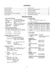
...) Gross Weight : 26 kg (57.33 lbs) -2- Luminance : 400(min), 500(Typ) 2-3. PC & Video Input 1)Input Form : AV, SVIDEO, Component1, Component2, RGB PC, DVI PC 2)Resolution(max) : Analog -1600 x 1200@60Hz Digital -1280 x 1024@60Hz 3-2. Power Consumption MODE H/V SYNC VIDEO POWER CONSUMPTION LED COLOR POWER ON (NORMAL) ON/ON ACTIVE less than 160 W GREEN STAND-BY OFF/ON OFF less than 4 W AMBER SUSPEND ON/OFF OFF less than...
...) Gross Weight : 26 kg (57.33 lbs) -2- Luminance : 400(min), 500(Typ) 2-3. PC & Video Input 1)Input Form : AV, SVIDEO, Component1, Component2, RGB PC, DVI PC 2)Resolution(max) : Analog -1600 x 1200@60Hz Digital -1280 x 1024@60Hz 3-2. Power Consumption MODE H/V SYNC VIDEO POWER CONSUMPTION LED COLOR POWER ON (NORMAL) ON/ON ACTIVE less than 160 W GREEN STAND-BY OFF/ON OFF less than 4 W AMBER SUSPEND ON/OFF OFF less than...
Service Manual
Page 3
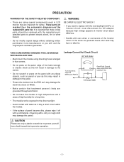
...; If the surface of panel become dirty, please wipe it may damage the electronic circuit (C-MOS). • Make certain that treatment person's body are grounded through wrist band. • Do not leave the module in high temperature and in LCD monitor that these critical parts should be replaced with care wires or connectors of the inverter circuit...
...; If the surface of panel become dirty, please wipe it may damage the electronic circuit (C-MOS). • Make certain that treatment person's body are grounded through wrist band. • Do not leave the module in high temperature and in LCD monitor that these critical parts should be replaced with care wires or connectors of the inverter circuit...
Service Manual
Page 4
... power source before connecting the test receiver positive lead. Do not test high voltage by static electricity. Use with this receiver only the test fixtures specified in this instrument and/or any receiver electrical plug or other voltage measuring device (DVM, FETVOM, etc) equipped with an electrolytic capacitor in an explosion hazard. Examples of a replacement ES device, touch...
... power source before connecting the test receiver positive lead. Do not test high voltage by static electricity. Use with this receiver only the test fixtures specified in this instrument and/or any receiver electrical plug or other voltage measuring device (DVM, FETVOM, etc) equipped with an electrolytic capacitor in an explosion hazard. Examples of a replacement ES device, touch...
Service Manual
Page 5
... connections. c. First, hold it . 3. "Small-Signal" Discrete Transistor Removal/Replacement 1. Securely crimp each transistor lead, and clip off excess lead. 6. Do not use the standard technique as the solder melts. 2. Removal 1. Use a mall wire-bristle (0.5 inch, or 1.25cm) brush with a small wire-bristle brush. c. Closely inspect the solder area and remove any excess or splashed solder with a metal handle. Power...
... connections. c. First, hold it . 3. "Small-Signal" Discrete Transistor Removal/Replacement 1. Securely crimp each transistor lead, and clip off excess lead. 6. Do not use the standard technique as the solder melts. 2. Removal 1. Use a mall wire-bristle (0.5 inch, or 1.25cm) brush with a small wire-bristle brush. c. Closely inspect the solder area and remove any excess or splashed solder with a metal handle. Power...
Service Manual
Page 6
...Connections To repair a defective copper pattern at IC connections use the following procedure to install a jumper wire on the copper pattern side of the circuit board. (Use this condition is encountered. carefully scratch away the solder resist and acrylic coating (if used) from or "lift-off any printed circuit board will not exist if the jumper wire opens. 2. At Other Connections Use...crimp it does not touch components or sharp edges. -6- Remove the defective copper pattern with a sharp knife. (Remove only as much copper as absolutely necessary). 2. Connect insulated 20-gauge ...
...Connections To repair a defective copper pattern at IC connections use the following procedure to install a jumper wire on the copper pattern side of the circuit board. (Use this condition is encountered. carefully scratch away the solder resist and acrylic coating (if used) from or "lift-off any printed circuit board will not exist if the jumper wire opens. 2. At Other Connections Use...crimp it does not touch components or sharp edges. -6- Remove the defective copper pattern with a sharp knife. (Remove only as much copper as absolutely necessary). 2. Connect insulated 20-gauge ...

Service Manual
Page 9
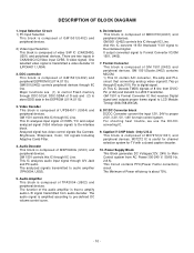
D-SUB DVI-D 128Mb DDR ( MT46V2 M32) RGB/SOG Dsub-H/V DDC_SCLA DDC_SDAA TMDS DDC_SCLB DDC_SDAB SCL/SDA SCL2/SDA2 VCHIP-SCL/VCHIP-SDA ADC TMDS gm1501H Video Signal Processor LVDS R,G,B Even Back-end Enhance R,G,B LVDS Tx R,G,B Even (THC63LVDM83R) 1 Ch 8Mb Flash Memory ( M2 9 W800AT) ITUR 601 (16Bit) H/V/CLK OUT Component 1(YPbPr,480i/480p/720p/1080i) SDRAM ( MT46V2...
D-SUB DVI-D 128Mb DDR ( MT46V2 M32) RGB/SOG Dsub-H/V DDC_SCLA DDC_SDAA TMDS DDC_SCLB DDC_SDAB SCL/SDA SCL2/SDA2 VCHIP-SCL/VCHIP-SDA ADC TMDS gm1501H Video Signal Processor LVDS R,G,B Even Back-end Enhance R,G,B LVDS Tx R,G,B Even (THC63LVDM83R) 1 Ch 8Mb Flash Memory ( M2 9 W800AT) ITUR 601 (16Bit) H/V/CLK OUT Component 1(YPbPr,480i/480p/720p/1080i) SDRAM ( MT46V2...
Service Manual
Page 10
... signal has video control signals like Contrast, Brightness, Sharpness, Color, tint signals Including Adaptive Comb Filter. 4. DC/DC Converter block DC/DC Converter convert the input 12V, 24V to store EDID data in CXA2040Q IC(Video input CVBS, S-video signal). Power Supply Block This Block generates DC Voltages(12V, 24V) to audio amplifier (TPA3004, U502). 6. One selected video signal is that converting analog video signal(0.7Vp-p) through A/V Jack and PC audio. GM 1501 controls...
... signal has video control signals like Contrast, Brightness, Sharpness, Color, tint signals Including Adaptive Comb Filter. 4. DC/DC Converter block DC/DC Converter convert the input 12V, 24V to store EDID data in CXA2040Q IC(Video input CVBS, S-video signal). Power Supply Block This Block generates DC Voltages(12V, 24V) to audio amplifier (TPA3004, U502). 6. One selected video signal is that converting analog video signal(0.7Vp-p) through A/V Jack and PC audio. GM 1501 controls...
Service Manual
Page 11
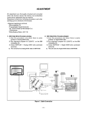
... Port Not used RS232C PARALLEL C VGS A MONITOR B V-SYNC ST POWER OFF ON 5V F Power inlet (required) 220 Power Select Switch (110V/220V) Power LED E ST Switch F V-Sync On/Off Switch (Switch must be following procedure and after warming up for L3200TC on the IBM compatible PC. 3) Select EEPROM → Analog EDID write command and Enter. 4) This will write the Digital EDID data to EEPROM. 2. ADJUSTMENT All adjustment are thoroughly checked...
... Port Not used RS232C PARALLEL C VGS A MONITOR B V-SYNC ST POWER OFF ON 5V F Power inlet (required) 220 Power Select Switch (110V/220V) Power LED E ST Switch F V-Sync On/Off Switch (Switch must be following procedure and after warming up for L3200TC on the IBM compatible PC. 3) Select EEPROM → Analog EDID write command and Enter. 4) This will write the Digital EDID data to EEPROM. 2. ADJUSTMENT All adjustment are thoroughly checked...
Service Manual
Page 12
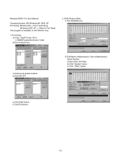
This program is available to "c:\WINNT\system32\drivers" folder b) Run Userport.exe 2. Port Setup a) Copy "UserPort.sys" file to LCD Monitor only. 1. EDID Read & Write 1) Run WinEDID.exe c) Remove all default number d) Add 300-3FF 2) Edit Week of Manufacture, Year of Manufacture, Serial Number a) Input User Info Data b) Click "Update" button c) Click " Write" button e) Click Start button. f) Click Exit button. - 12 - Windows EDID V1.0 User Manual Operating System: MS Windows 98, 2000, XP Port Setup: Windows 98 => Don't need setup Windows 2000, XP => Need to Port Setup.
This program is available to "c:\WINNT\system32\drivers" folder b) Run Userport.exe 2. Port Setup a) Copy "UserPort.sys" file to LCD Monitor only. 1. EDID Read & Write 1) Run WinEDID.exe c) Remove all default number d) Add 300-3FF 2) Edit Week of Manufacture, Year of Manufacture, Serial Number a) Input User Info Data b) Click "Update" button c) Click " Write" button e) Click Start button. f) Click Exit button. - 12 - Windows EDID V1.0 User Manual Operating System: MS Windows 98, 2000, XP Port Setup: Windows 98 => Don't need setup Windows 2000, XP => Need to Port Setup.
Service Manual
Page 13
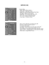
... reset and use - Resolution : Adjusts the picture resolution - SVC Display : Color of video input at the change - RS232 Select : Change RS232 Protocol - 13 - Hotel Mode : Enters with the menu which sets a hotel mode - Aging Mode : Sets the aging mode (User : OFF) - Video H Position : Horizontality position of video input at the change - WB Adjust : Adjusts the white balance - AI : Function built in panel - Model : Model or Micom Version - TV AV : TV Model, AV Model change - CNN : Use the CNN Option (only CNN version ON) - Model Select : Use the sizes Model...
... reset and use - Resolution : Adjusts the picture resolution - SVC Display : Color of video input at the change - RS232 Select : Change RS232 Protocol - 13 - Hotel Mode : Enters with the menu which sets a hotel mode - Aging Mode : Sets the aging mode (User : OFF) - Video H Position : Horizontality position of video input at the change - WB Adjust : Adjusts the white balance - AI : Function built in panel - Model : Model or Micom Version - TV AV : TV Model, AV Model change - CNN : Use the CNN Option (only CNN version ON) - Model Select : Use the sizes Model...
Service Manual
Page 14
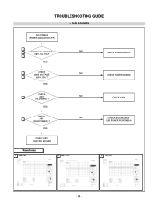
YES CHECK 7 J601 NO (SUB POWER) ? YES CHECK KEY CONTROL BOARD Waveforms 1 J601-18V 2 J601-12V CHECK POWER BOARD CHECK POWER BOARD CHECK X401 CHECK MICOM(U402) SUB POWER PORT(R634) 3 J601-5V - 14 - YES CHECK 6 X401 NO (14.318MHz) ? TROUBLESHOOTING GUIDE 1. NO POWER NO POWER (POWER INDICATOR OFF) 1 2 CHECK J601 VOLTAGE NO (18V, 12V, 5V)? 3 YES 4 CHECK NO J602 VOLTAGE 5 (24V, 33V) ?
YES CHECK 7 J601 NO (SUB POWER) ? YES CHECK KEY CONTROL BOARD Waveforms 1 J601-18V 2 J601-12V CHECK POWER BOARD CHECK POWER BOARD CHECK X401 CHECK MICOM(U402) SUB POWER PORT(R634) 3 J601-5V - 14 - YES CHECK 6 X401 NO (14.318MHz) ? TROUBLESHOOTING GUIDE 1. NO POWER NO POWER (POWER INDICATOR OFF) 1 2 CHECK J601 VOLTAGE NO (18V, 12V, 5V)? 3 YES 4 CHECK NO J602 VOLTAGE 5 (24V, 33V) ?

Service Manual
Page 17
... ON VIDEO SIGNAL INPUT NO RASTER ON VIDEO SIGNAL POWER CHECK OF CXA2040(U201) : U204(9V) POWER CHECK OF UPD64011(U904) : U905(3.3V), U906(1.5V) POWER CHECK OF MDIN150(U901) : U907(3.3V), U908(2.5V) POWER CHECK OF GM1501(U402) CHECK CABLE OF VIDEO/COMPONENT CHECK UPD64011(U904)I/O SIGNAL NO INPUT SIGNAL YES NO OUTPUT SIGNAL CHECK MDIN150(U901) AND SDRAM(U902) I/O SIGNAL YES CHECK GM1501(U402)AND SDRAM(U401) NO INPUT SIGNAL NO OUTPUT SIGNAL NO INPUT SIGNAL CHECK THE...
... ON VIDEO SIGNAL INPUT NO RASTER ON VIDEO SIGNAL POWER CHECK OF CXA2040(U201) : U204(9V) POWER CHECK OF UPD64011(U904) : U905(3.3V), U906(1.5V) POWER CHECK OF MDIN150(U901) : U907(3.3V), U908(2.5V) POWER CHECK OF GM1501(U402) CHECK CABLE OF VIDEO/COMPONENT CHECK UPD64011(U904)I/O SIGNAL NO INPUT SIGNAL YES NO OUTPUT SIGNAL CHECK MDIN150(U901) AND SDRAM(U902) I/O SIGNAL YES CHECK GM1501(U402)AND SDRAM(U401) NO INPUT SIGNAL NO OUTPUT SIGNAL NO INPUT SIGNAL CHECK THE...

Service Manual
Page 18
...) CHECK SOUND OF VCR,DVD,PC CHECK OF CONNECTION OF TUNER AND ANTENNA CHECK MSP3420G(U501) I/O SIGNAL YES NO INPUT SIGNAL NO OUTPUT SIGNAL NO INPUT SIGNAL CHECK TPA3004(U502) I/O SIGNAL YES NO OUTPUT SIGNAL CHECK SOUND INPUT =>PC SOUND(J707) =>VIDEO, DVD, DTV SOUND (RED, WHITE OF J701, J702) CHECK THE PERIPHERAL IC OF MSP3420G(U501) CHECK THE PERIPHERAL IC OF MSP3420G(U501) CHECK THE PERIPHERAL IC OF TPA3004(U502) CONNECTOR CHECK NO INPUT SIGNAL CHECK CONNECTION OF SPEAKER ON MONITOR - 18...
...) CHECK SOUND OF VCR,DVD,PC CHECK OF CONNECTION OF TUNER AND ANTENNA CHECK MSP3420G(U501) I/O SIGNAL YES NO INPUT SIGNAL NO OUTPUT SIGNAL NO INPUT SIGNAL CHECK TPA3004(U502) I/O SIGNAL YES NO OUTPUT SIGNAL CHECK SOUND INPUT =>PC SOUND(J707) =>VIDEO, DVD, DTV SOUND (RED, WHITE OF J701, J702) CHECK THE PERIPHERAL IC OF MSP3420G(U501) CHECK THE PERIPHERAL IC OF MSP3420G(U501) CHECK THE PERIPHERAL IC OF TPA3004(U502) CONNECTOR CHECK NO INPUT SIGNAL CHECK CONNECTION OF SPEAKER ON MONITOR - 18...

Service Manual
Page 19
5. NO RASTER STATE ON ANALOG SIGNAL NO RASTER ON ANALOG SIGNAL POWER CHECK OF GM1501(U402) POWER CHECK OF LVDS OUTPUT: J802 CONNECTOR(J101) CHECK NO INPUT SIGNAL CHECK ADC I/O SIGNAL IN GM1501(U402) YES NO OUTPUT SIGNAL NO INPUT SIGNAL CHECK GM1501(U402) I/O SIGNAL YES NO OUTPUT SIGNAL NO INPUT SIGNAL CHECK LVDS I/O SIGNAL NO OUTPUT SIGNAL CHECK THE PERIPHERAL IC OF D-SUB(J101) CHECK THE PERIPHERAL IC OF GM1501(U402) CHECK THE PERIPHERAL IC OF GM1501(U402) CHECK THE PERIPHERAL IC OF GM1501(U402) - 19 -
5. NO RASTER STATE ON ANALOG SIGNAL NO RASTER ON ANALOG SIGNAL POWER CHECK OF GM1501(U402) POWER CHECK OF LVDS OUTPUT: J802 CONNECTOR(J101) CHECK NO INPUT SIGNAL CHECK ADC I/O SIGNAL IN GM1501(U402) YES NO OUTPUT SIGNAL NO INPUT SIGNAL CHECK GM1501(U402) I/O SIGNAL YES NO OUTPUT SIGNAL NO INPUT SIGNAL CHECK LVDS I/O SIGNAL NO OUTPUT SIGNAL CHECK THE PERIPHERAL IC OF D-SUB(J101) CHECK THE PERIPHERAL IC OF GM1501(U402) CHECK THE PERIPHERAL IC OF GM1501(U402) CHECK THE PERIPHERAL IC OF GM1501(U402) - 19 -

Service Manual
Page 20
NO RASTER STATE ON DIGITAL SIGNAL NO RASTER STATEON DIGITAL SIGNAL POWER CHECK OF GM1501(U402) POWER CHECK OF LVDS OUTPUT: J802 CONNECTOR(J102) CHECK CHECK GM1501(U402) I/O SIGNAL YES CHECK LVDS I/O SIGNAL NO INPUT SIGNAL NO OUTPUT SIGNAL NO INPUT SIGNAL NO OUTPUT SIGNAL CHECK THE PERIPHERAL IC OF GM1501(U402) CHECK THE PERIPHERAL IC OF GM1501(U402) - 20 - 6.
NO RASTER STATE ON DIGITAL SIGNAL NO RASTER STATEON DIGITAL SIGNAL POWER CHECK OF GM1501(U402) POWER CHECK OF LVDS OUTPUT: J802 CONNECTOR(J102) CHECK CHECK GM1501(U402) I/O SIGNAL YES CHECK LVDS I/O SIGNAL NO INPUT SIGNAL NO OUTPUT SIGNAL NO INPUT SIGNAL NO OUTPUT SIGNAL CHECK THE PERIPHERAL IC OF GM1501(U402) CHECK THE PERIPHERAL IC OF GM1501(U402) - 20 - 6.
Service Manual
Page 21
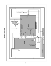
J502 9P 4P J402 WIRING DIAGRAM Connector Ass'y P/N: 6631T25024D J501 J610 Connector Ass'y P/N: 6631T25019G Connector Ass'y P/N: 6631T11012Q Connector Ass'y P/N: 6631T20032H Module Link MAIN Connector Ass'y P/N: 6631T20032H J608 J802(30Pin) to J607 12P J801 J802 10P 15P 15P 12P POWER Connector Ass'y P/N: 6631T20029C Connector Ass'y P/N: 6631T20029G LED CONTROL - 21 -
J502 9P 4P J402 WIRING DIAGRAM Connector Ass'y P/N: 6631T25024D J501 J610 Connector Ass'y P/N: 6631T25019G Connector Ass'y P/N: 6631T11012Q Connector Ass'y P/N: 6631T20032H Module Link MAIN Connector Ass'y P/N: 6631T20032H J608 J802(30Pin) to J607 12P J801 J802 10P 15P 15P 12P POWER Connector Ass'y P/N: 6631T20029C Connector Ass'y P/N: 6631T20029G LED CONTROL - 21 -

Service Manual
Page 23
... CABINET ASSEMBLY, L3200A BRAND 3090TKE018 -AV-SILVER 3091TKE022H CABINET ASSEMBLY, L3200A BRAND 3090TKE018 -AV-BLACK 020 6304FLP163A LCD(LIQUID CRYSTAL DISPLAY), LC320W01-A6 LG PHILPS TFT COLOR WXGA, 16:9, 500NITS, 16MS, 8BIT, LVDS or 6304FLP215A LCD(LIQUID CRYSTAL DISPLAY), LC320W01-A6K4 LG PHILPS TFT COLOR LEAD FREE 030 3809TKE021C BACK COVER ASSEMBLY, L3200A 3808TKE019 -AV 040 3043TKK213A TILT SWIVEL ASSEMBLY, L3200A 4950TKK983 STAND-Only L3200ATC,L3200AFC 050 6871TST481D PWB(PCB) ASSEMBLY,SUB, L3200TC CONTROL TOTAL...
... CABINET ASSEMBLY, L3200A BRAND 3090TKE018 -AV-SILVER 3091TKE022H CABINET ASSEMBLY, L3200A BRAND 3090TKE018 -AV-BLACK 020 6304FLP163A LCD(LIQUID CRYSTAL DISPLAY), LC320W01-A6 LG PHILPS TFT COLOR WXGA, 16:9, 500NITS, 16MS, 8BIT, LVDS or 6304FLP215A LCD(LIQUID CRYSTAL DISPLAY), LC320W01-A6K4 LG PHILPS TFT COLOR LEAD FREE 030 3809TKE021C BACK COVER ASSEMBLY, L3200A 3808TKE019 -AV 040 3043TKK213A TILT SWIVEL ASSEMBLY, L3200A 4950TKK983 STAND-Only L3200ATC,L3200AFC 050 6871TST481D PWB(PCB) ASSEMBLY,SUB, L3200TC CONTROL TOTAL...
Service Manual
Page 24
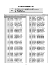
NO. DATE: 2005. 05. 19. PART NO. NO. MAIN BOARD CAPACITORS DATE: 2005. 05. 19. DESCRIPTION / SPECIFICATION C222 C225 C226 C227 C228 C229 C231 ... 0.1UF 50V 10% X7R 2012 R/TP 0.1UF 1608 50V 10% R/TP X7R - 24 - PART NO. DESCRIPTION / SPECIFICATION C1007 C1008 C1009 C1014 C1015 C1016 C1017 C1018 C1019 C1020 C1021 C1022 C1026 C1027 C1049 C1050 C1052 C1055 C1056... 50V 5% NP0 R/TP 2.2UF MV 50V 20% R/TP(SMD) S *S *AL LOC. REPLACEMENT PARTS LIST CAUTION: BEFORE REPLACING ANY OF THESE COMPONENTS, READ CAREFULLY THE SAFETY PRECAUTIONS IN THIS MANUAL. * NOTE : S SAFETY Mark AL ALTERNATIVE...
NO. DATE: 2005. 05. 19. PART NO. NO. MAIN BOARD CAPACITORS DATE: 2005. 05. 19. DESCRIPTION / SPECIFICATION C222 C225 C226 C227 C228 C229 C231 ... 0.1UF 50V 10% X7R 2012 R/TP 0.1UF 1608 50V 10% R/TP X7R - 24 - PART NO. DESCRIPTION / SPECIFICATION C1007 C1008 C1009 C1014 C1015 C1016 C1017 C1018 C1019 C1020 C1021 C1022 C1026 C1027 C1049 C1050 C1052 C1055 C1056... 50V 5% NP0 R/TP 2.2UF MV 50V 20% R/TP(SMD) S *S *AL LOC. REPLACEMENT PARTS LIST CAUTION: BEFORE REPLACING ANY OF THESE COMPONENTS, READ CAREFULLY THE SAFETY PRECAUTIONS IN THIS MANUAL. * NOTE : S SAFETY Mark AL ALTERNATIVE...
Service Manual
Page 28
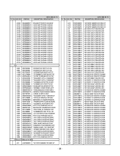
... COREs & FILTERs L511 6140TBZ007E "SLF12575T-330M3R2,TDK SMD CH" *S *AL LOC. NO. DATE: 2005. 05. 19. *S *AL LOC. DESCRIPTION / SPECIFICATION ZD602 ZD701 ZD704 ZD705 ZD706 ZD707 ZD708 ZD709 ZD710 ZD711 ZD712 ZD713 ZD714 ZD715 ZD716 ZD719 ZD720 ZD721 ZD722 ZD723 ZD724 0DZ330009DF 0DZ560009DA 0DZ560009DA 0DZ560009DA...EMP R/TP D" RC1117S-2.5 FAIRCHILD SOT-22 MAX232ACSE 16NARROW-SO RS232 74VHC157MX_NL FAIRCHILD 16PI "KA78M08R 3P,D-PAK TP VOL. NO. PART NO. DESCRIPTION / SPECIFICATION L512 L513 L514 L22 L23 L401 L402 L403 L404 L405 L406 L407 L408 L611 L613 L701 L702 L704 L705 L706 L707 L710...
... COREs & FILTERs L511 6140TBZ007E "SLF12575T-330M3R2,TDK SMD CH" *S *AL LOC. NO. DATE: 2005. 05. 19. *S *AL LOC. DESCRIPTION / SPECIFICATION ZD602 ZD701 ZD704 ZD705 ZD706 ZD707 ZD708 ZD709 ZD710 ZD711 ZD712 ZD713 ZD714 ZD715 ZD716 ZD719 ZD720 ZD721 ZD722 ZD723 ZD724 0DZ330009DF 0DZ560009DA 0DZ560009DA 0DZ560009DA...EMP R/TP D" RC1117S-2.5 FAIRCHILD SOT-22 MAX232ACSE 16NARROW-SO RS232 74VHC157MX_NL FAIRCHILD 16PI "KA78M08R 3P,D-PAK TP VOL. NO. PART NO. DESCRIPTION / SPECIFICATION L512 L513 L514 L22 L23 L401 L402 L403 L404 L405 L406 L407 L408 L611 L613 L701 L702 L704 L705 L706 L707 L710...


