
User Guide
Page 4
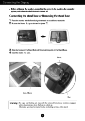
Align the hooks on a cushion or soft cloth. 2. Hook Stand Base Slot Warning : The tape and locking pin may be removed from those monitors equipped with the matching slots in figure 1 . 3. Insert the hooks into slots. A3 Rotate the Stand Body as shown in the Stand Base. 4. Otherwise, you ...may only be injured by the protruding sections of the stand. Connecting the Display Before setting up . Place the monitor with its front facing downward on the Stand Body with a standing base when the base is pulled up the...
Align the hooks on a cushion or soft cloth. 2. Hook Stand Base Slot Warning : The tape and locking pin may be removed from those monitors equipped with the matching slots in figure 1 . 3. Insert the hooks into slots. A3 Rotate the Stand Body as shown in the Stand Base. 4. Otherwise, you ...may only be injured by the protruding sections of the stand. Connecting the Display Before setting up . Place the monitor with its front facing downward on the Stand Body with a standing base when the base is pulled up the...
User Guide
Page 5
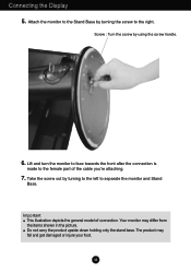
... in the picture. Important This illustration depicts the general model of the cable you're attaching. 7. Attach the monitor to the Stand Base by turning to the left to separate the monitor and Stand Base. A4 Take the screw out by turning the screw to the female part of connection. Screw... : Turn the screw by using the screw handle. 6. Your monitor may fall and get damaged or injure your foot. Connecting the Display 5. Lift and turn the monitor to face towards the front after the connection is made to the right.
... in the picture. Important This illustration depicts the general model of the cable you're attaching. 7. Attach the monitor to the Stand Base by turning to the left to separate the monitor and Stand Base. A4 Take the screw out by turning the screw to the female part of connection. Screw... : Turn the screw by using the screw handle. 6. Your monitor may fall and get damaged or injure your foot. Connecting the Display 5. Lift and turn the monitor to face towards the front after the connection is made to the right.
User Guide
Page 6
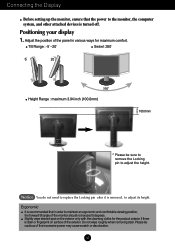
...if there is turned off. Notice You do not need to adjust the height. A5 Slightly wipe stained spot on surface of the monitor should not exceed 5 degrees. Positioning your display 1. Adjust the position of the panel in order to adjust its height. Connecting the... Display Before setting up the monitor, ensure that excessive power may cause scratch or discoloration. Ergonomic It is removed, to maintain an ergonomic and comfortable viewing position, the ...
...if there is turned off. Notice You do not need to adjust the height. A5 Slightly wipe stained spot on surface of the monitor should not exceed 5 degrees. Positioning your display 1. Adjust the position of the panel in order to adjust its height. Connecting the... Display Before setting up the monitor, ensure that excessive power may cause scratch or discoloration. Ergonomic It is removed, to maintain an ergonomic and comfortable viewing position, the ...

User Guide
Page 7
If the monitor head touches the Stand Base, then the Stand Base could crack. A6 For detailed information, please refer to utilize the Pivot function. 2. Landscape & Portrait : You can rotate the panel 90o clockwise. Lift the monitor to its highest height to the Pivot Software CD provided. Please be cautious and avoid contact between the monitor head and the Stand Base when rotating the screen to access the Pivot function. Connecting the Display Using the Pivot function 1. Head section Stand section 3.
If the monitor head touches the Stand Base, then the Stand Base could crack. A6 For detailed information, please refer to utilize the Pivot function. 2. Landscape & Portrait : You can rotate the panel 90o clockwise. Lift the monitor to its highest height to the Pivot Software CD provided. Please be cautious and avoid contact between the monitor head and the Stand Base when rotating the screen to access the Pivot function. Connecting the Display Using the Pivot function 1. Head section Stand section 3.

User Guide
Page 8
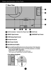
... 3 Audio DC-In Cable DC-OUT Notice Be cautious to avoid your hand being caught between the speaker and Stand Base when lowering the monitor to its lowest height, with the speaker fully equipped. 4. After connecting the speaker, connect the Audio DC-IN cable to the AUDIO-IN... HDMI/DVI OUT AUDIO 2 1 DC-OUT HDMI/DVI COMPONENT Y PB PR D-SUB 2. When using HDMI, you can connect the monitor's to the appropriate female socket of the monitor's back slot until you hear the clicking sound. 3. A7 Connecting the speakers - Insert the projecting hook of the speaker in the ...
... 3 Audio DC-In Cable DC-OUT Notice Be cautious to avoid your hand being caught between the speaker and Stand Base when lowering the monitor to its lowest height, with the speaker fully equipped. 4. After connecting the speaker, connect the Audio DC-IN cable to the AUDIO-IN... HDMI/DVI OUT AUDIO 2 1 DC-OUT HDMI/DVI COMPONENT Y PB PR D-SUB 2. When using HDMI, you can connect the monitor's to the appropriate female socket of the monitor's back slot until you hear the clicking sound. 3. A7 Connecting the speakers - Insert the projecting hook of the speaker in the ...
User Guide
Page 9
... configuration.. *AUDIO-OUT is only available with the HDMI input. (You cannot use it with D-SUB or any other component.) The Left Rear of the Monitor OUT AUDIO 2 1 AUDIO OUT UB A8
... configuration.. *AUDIO-OUT is only available with the HDMI input. (You cannot use it with D-SUB or any other component.) The Left Rear of the Monitor OUT AUDIO 2 1 AUDIO OUT UB A8
User Guide
Page 10
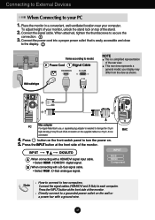
... HDMI Component Note How to connect to change the 15 pin high density (3 row) D-sub VGA connector on top of the monitor. Place the monitor in a convenient, well-ventilated location near your PC 1. connection. Wall-outlet type PC Mac adapter For Apple Macintosh use, ... with a D-Sub signal cable. • Select RGB : D-Sub analogue signal. Connect the signal cable. This rear view represents a general model; your monitor, unlock the stand lock on the supplied cable to a grounded power outlet on . 5. Directly connect to a 15 pin 2 row MAC connector. 4. ...
... HDMI Component Note How to connect to change the 15 pin high density (3 row) D-sub VGA connector on top of the monitor. Place the monitor in a convenient, well-ventilated location near your PC 1. connection. Wall-outlet type PC Mac adapter For Apple Macintosh use, ... with a D-Sub signal cable. • Select RGB : D-Sub analogue signal. Connect the signal cable. This rear view represents a general model; your monitor, unlock the stand lock on the supplied cable to a grounded power outlet on . 5. Directly connect to a 15 pin 2 row MAC connector. 4. ...

User Guide
Page 11
...cord. INPUT RGB HDMI Component A10 Speaker AUDIO IN DC-OUT HDMI/DVI COMPONENT Y PB PR D-SUB 1 2 AUDIO OUT PB PR PB PR Monitor RCA-Stereo cable (not included) Component Cable (not included) DVD/VIDEO/HDTV PB PR PB PR DVD/VIDEO/HDTV 3. Connect the Component cables and... RCA to the sockets of the monitor. INPUT OK/AUTO A When connecting with a Component cable 1. Connect the terminals to Stereo cables properly. Connecting to External Devices When Watching DVD/Video...
...cord. INPUT RGB HDMI Component A10 Speaker AUDIO IN DC-OUT HDMI/DVI COMPONENT Y PB PR D-SUB 1 2 AUDIO OUT PB PR PB PR Monitor RCA-Stereo cable (not included) Component Cable (not included) DVD/VIDEO/HDTV PB PR PB PR DVD/VIDEO/HDTV 3. Connect the Component cables and... RCA to the sockets of the monitor. INPUT OK/AUTO A When connecting with a Component cable 1. Connect the terminals to Stereo cables properly. Connecting to External Devices When Watching DVD/Video...
User Guide
Page 12
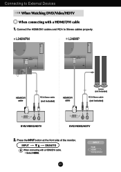
A11 INPUT RGB HDMI Component Press the INPUT button at the front side of the monitor. L246WPM L246WP OUT AUDIO OUT AUDIO 2 2 1 1 COMPONENT DC-OUT HDMI/DVI Y PB PR D-SUB AUDIO IN COMPONENT DC-OUT HDMI/DVI Y PB PR D-SUB HDMI/DVI cable ...
A11 INPUT RGB HDMI Component Press the INPUT button at the front side of the monitor. L246WPM L246WP OUT AUDIO OUT AUDIO 2 2 1 1 COMPONENT DC-OUT HDMI/DVI Y PB PR D-SUB AUDIO IN COMPONENT DC-OUT HDMI/DVI Y PB PR D-SUB HDMI/DVI cable ...
User Guide
Page 13
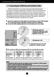
Connect the USB compliant peripherals to be attached it. 1. The monitor's USB terminal supports USB 2.0 and High Speed cables. This display has an integrated BUSpowered USB hub, allowing up to 2 other peripherals to your display instead ...
Connect the USB compliant peripherals to be attached it. 1. The monitor's USB terminal supports USB 2.0 and High Speed cables. This display has an integrated BUSpowered USB hub, allowing up to 2 other peripherals to your display instead ...

User Guide
Page 14
L246WPM Side Jack Headphone/Earphone Input Automatically mutes the speaker volume when the headphones are plugged in. To connect your PC, plug the cable into the Audio-Out of your audio component, plug the cable into the external audio component. - Rear AUDIO IN Audio Input - To connect HDMI, plug the cable into the sound card *Line Out on the PC. - Speaker Out *Line Out A13 Using the speakers - The feature is only for speaker models - To connect your monitor.
L246WPM Side Jack Headphone/Earphone Input Automatically mutes the speaker volume when the headphones are plugged in. To connect your PC, plug the cable into the Audio-Out of your audio component, plug the cable into the external audio component. - Rear AUDIO IN Audio Input - To connect HDMI, plug the cable into the sound card *Line Out on the PC. - Speaker Out *Line Out A13 Using the speakers - The feature is only for speaker models - To connect your monitor.
User Guide
Page 15
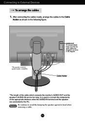
... the AUDIO-IN terminal and the speaker are plugged in as shown in the diagram. Cable Holder *The length of the cable which connects the monitor's AUDIO-OUT and the speaker's AUDIO-IN can be too long. AUDIO *The speaker is used to the PC. It is only for speaker models...
... the AUDIO-IN terminal and the speaker are plugged in as shown in the diagram. Cable Holder *The length of the cable which connects the monitor's AUDIO-OUT and the speaker's AUDIO-IN can be too long. AUDIO *The speaker is used to the PC. It is only for speaker models...
User Guide
Page 17
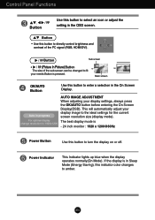
... Mode (Energy Saving), this indicator color changes to the ideal settings for the current screen resolution size (display mode). If the display is - 24 inch monitor : 1920 x 1200@60Hz Power Button Use this button to turn the display on or off.
... Mode (Energy Saving), this indicator color changes to the ideal settings for the current screen resolution size (display mode). If the display is - 24 inch monitor : 1920 x 1200@60Hz Power Button Use this button to turn the display on or off.
User Guide
Page 22
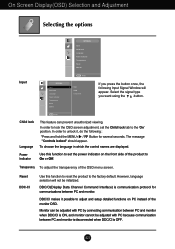
...signal type you press the button once, the following : *Press and hold the MENU+ Button for communications between PC and monitor when DDC/CI is ON, and monitor cannot be initialized. A21 In order to the 'On' position. Reset DDC-CI Use this function to set the Child ...Off. DDC/CI makes it , do the following Input Signal Window will not be adjusted with PC by connecting communication between PC and monitor. On Screen Display(OSD) Selection and Adjustment Selecting the options Input Input Child Lock Language Power Indicator Transparency Reset DDC-CI Input Child ...
...signal type you press the button once, the following : *Press and hold the MENU+ Button for communications between PC and monitor when DDC/CI is ON, and monitor cannot be initialized. A21 In order to the 'On' position. Reset DDC-CI Use this function to set the Child ...Off. DDC/CI makes it , do the following Input Signal Window will not be adjusted with PC by connecting communication between PC and monitor. On Screen Display(OSD) Selection and Adjustment Selecting the options Input Input Child Lock Language Power Indicator Transparency Reset DDC-CI Input Child ...
User Guide
Page 27
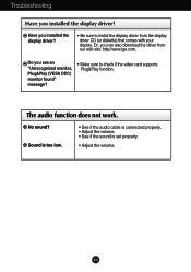
... work. Do you installed the display driver? • Be sure to check if the video card supports Plug&Play function. Have you see an "Unrecognized monitor, Plug&Play (VESA DDC) monitor found" message? • Make sure to install the display driver from our web site: http://www.lge.com. A26
... work. Do you installed the display driver? • Be sure to check if the video card supports Plug&Play function. Have you see an "Unrecognized monitor, Plug&Play (VESA DDC) monitor found" message? • Make sure to install the display driver from our web site: http://www.lge.com. A26
User Guide
Page 34
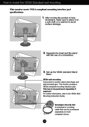
... Guide. Separate the head and the stand with the use of a screwdriver. VESA wall mounting Connected to Install the VESA Standard wall mounting This monitor meets VESA-compliant mounting interface pad specifications. 1. A33 OUT AUDIO 2 1 DC-OUT HDMI/DVI COMPONENT Y PB PR D-SUB DC-OUT HDMI.../DVI COMPONENT Y PB PR D-SUB 1 2 AUDIO OUT 3. Set up the VESA standard Stand Base. This monitor accepts a VESA-compliant mounting interface pad.This has to avoid surface damage. How to another object (stand type and wall-mounted type. After moving...
... Guide. Separate the head and the stand with the use of a screwdriver. VESA wall mounting Connected to Install the VESA Standard wall mounting This monitor meets VESA-compliant mounting interface pad specifications. 1. A33 OUT AUDIO 2 1 DC-OUT HDMI/DVI COMPONENT Y PB PR D-SUB DC-OUT HDMI.../DVI COMPONENT Y PB PR D-SUB 1 2 AUDIO OUT 3. Set up the VESA standard Stand Base. This monitor accepts a VESA-compliant mounting interface pad.This has to avoid surface damage. How to another object (stand type and wall-mounted type. After moving...


