Service Manual
Page 1
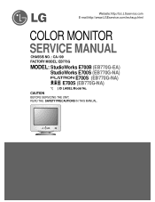
Website:http://biz.LGservice.com E-mail:http://www.LGEservice.com/techsup.html COLOR MONITOR SERVICE MANUAL CHASSIS NO. : CA-109 FACTORY MODEL: EB770G MODEL: StudioWorks E700B (EB770G-EA) StudioWorks E700S (EB770G-NA) E700S (EB770G-NA) E700S (EB770G-NA) *( ) ID LABEL Model No. CAUTION BEFORE SERVICING THE UNIT, READ THE SAFETY PRECAUTIONS IN THIS MANUAL. MENU SELECT
Website:http://biz.LGservice.com E-mail:http://www.LGEservice.com/techsup.html COLOR MONITOR SERVICE MANUAL CHASSIS NO. : CA-109 FACTORY MODEL: EB770G MODEL: StudioWorks E700B (EB770G-EA) StudioWorks E700S (EB770G-NA) E700S (EB770G-NA) E700S (EB770G-NA) *( ) ID LABEL Model No. CAUTION BEFORE SERVICING THE UNIT, READ THE SAFETY PRECAUTIONS IN THIS MANUAL. MENU SELECT
Service Manual
Page 2
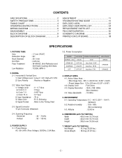
...5V 2) Sync Polarity : Positive or Negative 2-2. WEIGHT (with TILT/SWIVEL) Width : 400.0 mm (15.74 inch) Depth : 424.0 mm (16.70 inch) Height : 395.0 mm (15.55 inch) 7. SIGNAL 2-1. Display Resolution : 1024 x 768 / 85Hz (Non-Interlace) 4-4. CONTENTS SPECIFICATIONS 2 SAFETY PRECAUTIONS 3 TIMING CHART 4 OPERATING INSTRUCTIONS 5 WIRING DIAGRAM 6 DISASSEMBLY 7 BLOCK DIAGRAM 8 DESCRIPTION OF BLOCK DIAGRAM 9 ADJUSTMENT 11 TROUBLESHOOTING GUIDE 13 EXPLODED VIEW 23 EXPLODED VIEW PARTS LIST 24 REPLACEMENT PARTS LIST 25 PIN CONFIGURATION 30 SCHEMATIC DIAGRAM 36...
...5V 2) Sync Polarity : Positive or Negative 2-2. WEIGHT (with TILT/SWIVEL) Width : 400.0 mm (15.74 inch) Depth : 424.0 mm (16.70 inch) Height : 395.0 mm (15.55 inch) 7. SIGNAL 2-1. Display Resolution : 1024 x 768 / 85Hz (Non-Interlace) 4-4. CONTENTS SPECIFICATIONS 2 SAFETY PRECAUTIONS 3 TIMING CHART 4 OPERATING INSTRUCTIONS 5 WIRING DIAGRAM 6 DISASSEMBLY 7 BLOCK DIAGRAM 8 DESCRIPTION OF BLOCK DIAGRAM 9 ADJUSTMENT 11 TROUBLESHOOTING GUIDE 13 EXPLODED VIEW 23 EXPLODED VIEW PARTS LIST 24 REPLACEMENT PARTS LIST 25 PIN CONFIGURATION 30 SCHEMATIC DIAGRAM 36...
Service Manual
Page 3
... transformer must be inserted between the color monitor and AC power line before monitor power on the schematic diagram and the replacement parts list. The following safety checks and servicing guidelines. The high voltage meter should be paid to pin-connector (P902) in the deflection circuits. Use only same type display tubes. -3- These parts are thoroughly familiar with all parts which have been overheated as the...
... transformer must be inserted between the color monitor and AC power line before monitor power on the schematic diagram and the replacement parts list. The following safety checks and servicing guidelines. The high voltage meter should be paid to pin-connector (P902) in the deflection circuits. Use only same type display tubes. -3- These parts are thoroughly familiar with all parts which have been overheated as the...
Service Manual
Page 5
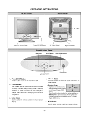
...(OSD) system. The Brightness and Contrast functions are also available in DPMS (Energy Saving) mode, - in the On Screen Display (OSD) menu. 5. its color changes to save all changes. OPERATING INSTRUCTIONS FRONT VIEW REAR VIEW MENU SELECT ID Label See Front Control Panel Power ON/OFF Button AC Power Socket Signal Connector Front Control Panel MENU Button SELECT Button Power (DPMS) Indicator MENU SELECT Buttons Power Button 1. MENU Button Use this button to choose or adjust items in the on screen display. -5- Button Use these buttons to turn the monitor...
...(OSD) system. The Brightness and Contrast functions are also available in DPMS (Energy Saving) mode, - in the On Screen Display (OSD) menu. 5. its color changes to save all changes. OPERATING INSTRUCTIONS FRONT VIEW REAR VIEW MENU SELECT ID Label See Front Control Panel Power ON/OFF Button AC Power Socket Signal Connector Front Control Panel MENU Button SELECT Button Power (DPMS) Indicator MENU SELECT Buttons Power Button 1. MENU Button Use this button to choose or adjust items in the on screen display. -5- Button Use these buttons to turn the monitor...
Service Manual
Page 7
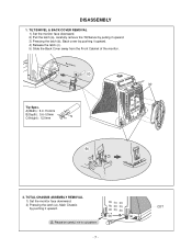
... COVER REMOVAL 1) Set the monitor face downward. 2) Pull the latch (a), carefully remove the Tilt/Swivel by pulling it upward. 3) Pressing the latch (b), Back cover by pushing it upward. 4) Release the latch (c). 5) Slide the Back Cover away from the Front Cabinet of the monitor. A(Width) : 5.0~15.0mm B(Depth) : 0.6~0.9mm C(Height) : 12.0mm C Tip AB (b) 1 3 3 2 2 2. Back Cover (c) Cabinet (a) Tip Spec. CDT DISASSEMBLY 1. TOTAL CHASSIS ASSEMBLY REMOVAL 1) Set the monitor...
... COVER REMOVAL 1) Set the monitor face downward. 2) Pull the latch (a), carefully remove the Tilt/Swivel by pulling it upward. 3) Pressing the latch (b), Back cover by pushing it upward. 4) Release the latch (c). 5) Slide the Back Cover away from the Front Cabinet of the monitor. A(Width) : 5.0~15.0mm B(Depth) : 0.6~0.9mm C(Height) : 12.0mm C Tip AB (b) 1 3 3 2 2 2. Back Cover (c) Cabinet (a) Tip Spec. CDT DISASSEMBLY 1. TOTAL CHASSIS ASSEMBLY REMOVAL 1) Set the monitor...

Service Manual
Page 8
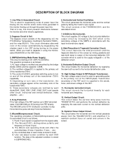
< OSD Control > BLOCK DIAGRAM Dynamic Focus Static Focus G1 Screen(G2) -8- SELECT 80V H.V OSD ON/OFF POWER BRIGHTNESS CONTRAST H / V POSITION H-Sync Sig V-Sync Sig Signal Cable R G I2C DATA(SDA) B I2C CLOCK(SCL) VIDEO PRE-AMP (IC302) LM1269 VIDEO MAIN AMP (IC303) LM2469 Heater ( 6.3V ) DY CDT H / V SIZE H CORNER SPCC TRAPEZOID PIN BALANCE PARALLELOGRAM ROTATION MICOM (IC401) SCL / SDA 5V H/V Sync, PWM Control OSD IC 5V (IC301) 5V I2C MTV038-15...
< OSD Control > BLOCK DIAGRAM Dynamic Focus Static Focus G1 Screen(G2) -8- SELECT 80V H.V OSD ON/OFF POWER BRIGHTNESS CONTRAST H / V POSITION H-Sync Sig V-Sync Sig Signal Cable R G I2C DATA(SDA) B I2C CLOCK(SCL) VIDEO PRE-AMP (IC302) LM1269 VIDEO MAIN AMP (IC303) LM2469 Heater ( 6.3V ) DY CDT H / V SIZE H CORNER SPCC TRAPEZOID PIN BALANCE PARALLELOGRAM ROTATION MICOM (IC401) SCL / SDA 5V H/V Sync, PWM Control OSD IC 5V (IC301) 5V I2C MTV038-15...
Service Manual
Page 9
... the TDA4857(IC701) and performs the vertical deflection by taking the H and V sync signal. X-ray Protection. This circuit makes the horizontal deflection by supplying the saw -tooth wave to degauss in the CRT during turning on center and corners in itself. 5) User can adjust screen condition by degaussing the shadow mask in using the monitor, select DEGAUSS on turn ratio of the transformer, the...
... the TDA4857(IC701) and performs the vertical deflection by taking the H and V sync signal. X-ray Protection. This circuit makes the horizontal deflection by supplying the saw -tooth wave to degauss in the CRT during turning on center and corners in itself. 5) User can adjust screen condition by degaussing the shadow mask in using the monitor, select DEGAUSS on turn ratio of the transformer, the...
Service Manual
Page 10
... by changing DC level of the G1. 15. And Brightness circuit is attached near the deflection yoke of the CRT. 14. This circuit corrects the tilt of the screen brightness by taking the clamp, R, G, B drive and contrast signal from the Micom(IC401). 17. H & V Blanking and Brightness Control. Video Pre-Amp Circuit. This circuit amplifies the video signal which is used for control of the screen by supplying...
... by changing DC level of the G1. 15. And Brightness circuit is attached near the deflection yoke of the CRT. 14. This circuit corrects the tilt of the screen brightness by taking the clamp, R, G, B drive and contrast signal from the Micom(IC401). 17. H & V Blanking and Brightness Control. Video Pre-Amp Circuit. This circuit amplifies the video signal which is used for control of the screen by supplying...
Service Manual
Page 11
... 1. Set external Brightness and Contrast volume to 19) 20) PRESET EXIT → Y (Yes) command. 4. Adjust G2 (screen) command to 0.4± 0.05FL of the raster luminance. 8) Adjust R-BIAS and G-BIAS command to x=0.283± 0.005 and y=0.298±0.005 on the White Balance Meter with saved each mode data. - Alignment Adaptor and Software. - Install the cable for adjustment such as arrow keys to be the best...
... 1. Set external Brightness and Contrast volume to 19) 20) PRESET EXIT → Y (Yes) command. 4. Adjust G2 (screen) command to 0.4± 0.05FL of the raster luminance. 8) Adjust R-BIAS and G-BIAS command to x=0.283± 0.005 and y=0.298±0.005 on the White Balance Meter with saved each mode data. - Alignment Adaptor and Software. - Install the cable for adjustment such as arrow keys to be the best...
Service Manual
Page 12
.... 20) Display color 15,0 full white patten at Mode 4. 21) Set Brightness and Contrast to Max position. 22) COLOR ADJ. → LUMINANCE → ABL command. 23) Adjust ABL to max position. 2) Display H character in full screen at Mode 4. 2) EEPROM → Write EDID command and confirm "EDID Write OK!!" message of monitor. 3) Exit from the program. 5. Input EDID Data. 1) Display color 15,0 cross hatch pattern at Mode 4. 3) Adjust two Focus control on...
.... 20) Display color 15,0 full white patten at Mode 4. 21) Set Brightness and Contrast to Max position. 22) COLOR ADJ. → LUMINANCE → ABL command. 23) Adjust ABL to max position. 2) Display H character in full screen at Mode 4. 2) EEPROM → Write EDID command and confirm "EDID Write OK!!" message of monitor. 3) Exit from the program. 5. Input EDID Data. 1) Display color 15,0 cross hatch pattern at Mode 4. 3) Adjust two Focus control on...

Service Manual
Page 13
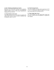
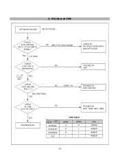
YES TROUBLE IN Q903, Q952, Q951, Q942, Q941 NO NO NO NO - 13 - TROUBLESHOOTING GUIDE 1. NO POWER NO POWER (POWER INDICATOR OFF) CHECK FUSE OK? (F901) YES CHECK C908 VOLTAGE? (AC120V: 160VDC, AC220V: 304VDC) YES CHECK IC901 PIN 6 WAVEFORM (SQUARE WAVE COMES OUT?) YES CHECK D941, D942, D951, D961, D962, D971 VOLTAGE? TROUBLE IN FUSE (F901) TROUBLE IN D900 TROUBLE IN IC901 TROUBLE IN D941, D942, D951, D961, D962, D971
YES TROUBLE IN Q903, Q952, Q951, Q942, Q941 NO NO NO NO - 13 - TROUBLESHOOTING GUIDE 1. NO POWER NO POWER (POWER INDICATOR OFF) CHECK FUSE OK? (F901) YES CHECK C908 VOLTAGE? (AC120V: 160VDC, AC220V: 304VDC) YES CHECK IC901 PIN 6 WAVEFORM (SQUARE WAVE COMES OUT?) YES CHECK D941, D942, D951, D961, D962, D971 VOLTAGE? TROUBLE IN FUSE (F901) TROUBLE IN D900 TROUBLE IN IC901 TROUBLE IN D941, D942, D951, D961, D962, D971
Service Manual
Page 20
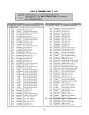
CHECK PC, (PC IS NOT GOING INTO DPM OFF MODE) TROUBLE IN X401 TROUBLE IN IC401 (MICOM) TROUBLE IN Q941, Q942, Q951, Q952 YES TROUBLE IN PC Mode Item NORMAL STAND-BY SUSPEND OFF DPM TABLE DPMF H H H L DPMS H L L L LED GREEN AMBER AMBER AMBER - 20 - 8. TROUBLE IN DPM OFF MODE FAILURE (NO OFF MODE.) CHECK IC401 (MICOM) PIN 31, 32 (H/V INPUT) SIGNAL? SEE DPM TABLE YES NO NO (DPMF: 0V) CHECK B+ LINE NO (6.3V,15V, 80V) ? YES H/V SYNC NO INPUT H/V SYNC SIGNAL CHECK IC401 PIN 13 WAVEFORM? 5V 24MHz YES CHECK IC401 (MICOM) PIN 2, 3 ?
CHECK PC, (PC IS NOT GOING INTO DPM OFF MODE) TROUBLE IN X401 TROUBLE IN IC401 (MICOM) TROUBLE IN Q941, Q942, Q951, Q952 YES TROUBLE IN PC Mode Item NORMAL STAND-BY SUSPEND OFF DPM TABLE DPMF H H H L DPMS H L L L LED GREEN AMBER AMBER AMBER - 20 - 8. TROUBLE IN DPM OFF MODE FAILURE (NO OFF MODE.) CHECK IC401 (MICOM) PIN 31, 32 (H/V INPUT) SIGNAL? SEE DPM TABLE YES NO NO (DPMF: 0V) CHECK B+ LINE NO (6.3V,15V, 80V) ? YES H/V SYNC NO INPUT H/V SYNC SIGNAL CHECK IC401 PIN 13 WAVEFORM? 5V 24MHz YES CHECK IC401 (MICOM) PIN 2, 3 ?

Service Manual
Page 24
INDIA) 10 6850TA9004A CABLE,D-SUB UL 2990-9C(7.5) AT 1560MM GLAY CB777G DM 11 4950TKS169A METAL SHIELD BOTTOM(A-CKD) 12 4930TKK031C HOLDER, PCB FIX , PC+ABS 13 4810TKK171B BRACKET, EB770F SUPPORTER CDT 14 6634TFZ002A ADAPTER, SIGNAL, LIBERTY ENHANCE MAC 6-DIP (JAPAN ONLY) 15 381-240A ADAPTER,AC, KPR-24 KAWASAKI 125V 15A BLACK (JAPAN ONLY) 3313T17251C MAIN TOTAL ASSEMBLY, EB770G...
INDIA) 10 6850TA9004A CABLE,D-SUB UL 2990-9C(7.5) AT 1560MM GLAY CB777G DM 11 4950TKS169A METAL SHIELD BOTTOM(A-CKD) 12 4930TKK031C HOLDER, PCB FIX , PC+ABS 13 4810TKK171B BRACKET, EB770F SUPPORTER CDT 14 6634TFZ002A ADAPTER, SIGNAL, LIBERTY ENHANCE MAC 6-DIP (JAPAN ONLY) 15 381-240A ADAPTER,AC, KPR-24 KAWASAKI 125V 15A BLACK (JAPAN ONLY) 3313T17251C MAIN TOTAL ASSEMBLY, EB770G...
Service Manual
Page 25
... J POLY NI TP 362J 20.0*12.0*7.0*10.0 800V J 100PF 2KV K B TR 22UF SHL,SD 50V M FM5 TP 5 - 25 - DESCRIPTION / SPECIFICATION C201 C301 C302 C303 C304 C305 C306 C307 C308 C309 C310 C311 C312 C313 C314 C315 C316 C317 C318 C319 C320 C321 C322 C323 C324... B TS 0.1UF 50V Z F TR 0.1M 50V Z F TA52 MODEL: (EB770G-EA), (EB770G-NA) DATE: 2002. 1. 10. *S *AL LOC. REPLACEMENT PARTS LIST CAUTION: BEFORE REPLACING ANY OF THESE COMPONENTS, READ CAREFULLY THE SAFETY PRECAUTIONS IN THIS MANUAL. * NOTE : S SAFETY Mark AL ALTERNATIVE PARTS MODEL: (EB770G-EA), (EB770G-NA) *S *AL LOC. CAPACITORS DATE: 2002...
... J POLY NI TP 362J 20.0*12.0*7.0*10.0 800V J 100PF 2KV K B TR 22UF SHL,SD 50V M FM5 TP 5 - 25 - DESCRIPTION / SPECIFICATION C201 C301 C302 C303 C304 C305 C306 C307 C308 C309 C310 C311 C312 C313 C314 C315 C316 C317 C318 C319 C320 C321 C322 C323 C324... B TS 0.1UF 50V Z F TR 0.1M 50V Z F TA52 MODEL: (EB770G-EA), (EB770G-NA) DATE: 2002. 1. 10. *S *AL LOC. REPLACEMENT PARTS LIST CAUTION: BEFORE REPLACING ANY OF THESE COMPONENTS, READ CAREFULLY THE SAFETY PRECAUTIONS IN THIS MANUAL. * NOTE : S SAFETY Mark AL ALTERNATIVE PARTS MODEL: (EB770G-EA), (EB770G-NA) *S *AL LOC. CAPACITORS DATE: 2002...

Service Manual
Page 30
...DIAGRAM P0.0-P0.7/INT0-INT2 P2.0-P2.7 XIN XOUT PWM0 PWM6 Vsync-I Hsync-I Csync-I Vsync-O Hsync-O Clamp-O TM0CAP RESET INT0-INT2 Main Osc 8-Bit PWM (7-Ch) Sync Processor 8-Bit Counter (Tmer M0) Port 0 Port 2 I/O Port and Interrupt Control ...SAM8 CPU 32/48* Kbyte ROM 784/1040Byte Register File VDD1, VDD2 VSS1, VSS2 TEST Port 1 Port 3 ADC Stave Only IIC-Bus *S3C8639 - 32Kbyte ROM - 784 Byte RAM *S3C863A - 48 Kbyte ROM - 1040 Byte RAM 12-Bit Counter (Timer M1) Interval Timer (Timer M2) Multi-master...
...DIAGRAM P0.0-P0.7/INT0-INT2 P2.0-P2.7 XIN XOUT PWM0 PWM6 Vsync-I Hsync-I Csync-I Vsync-O Hsync-O Clamp-O TM0CAP RESET INT0-INT2 Main Osc 8-Bit PWM (7-Ch) Sync Processor 8-Bit Counter (Tmer M0) Port 0 Port 2 I/O Port and Interrupt Control ...SAM8 CPU 32/48* Kbyte ROM 784/1040Byte Register File VDD1, VDD2 VSS1, VSS2 TEST Port 1 Port 3 ADC Stave Only IIC-Bus *S3C8639 - 32Kbyte ROM - 784 Byte RAM *S3C863A - 48 Kbyte ROM - 1040 Byte RAM 12-Bit Counter (Timer M1) Interval Timer (Timer M2) Multi-master...
Service Manual
Page 31
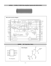
LM1269 110 MHz I2C RGB Video Amplifier System with OSD & DACs 24 13 1 12 Block and Connection Diagram R OSD 1 G OSD 2 B OSD 3 OSD Select 4 R Video 5 G Video 6 B Video 7 Analog GND 8 Vcc 9 VREFREXT 10 SDA 11 SCL 12 R Analog/ Digital R To Other Video Channels OSD Contrast Clamp DC Restore Amp H Blank Hi Z Input Buffer Amp R Contrast Auto Beam Limit Amp OSD Mixer R Gain Output Buffer Amp Register's To internal Block with "R" I2C Interface VREF R DACs DC...
LM1269 110 MHz I2C RGB Video Amplifier System with OSD & DACs 24 13 1 12 Block and Connection Diagram R OSD 1 G OSD 2 B OSD 3 OSD Select 4 R Video 5 G Video 6 B Video 7 Analog GND 8 Vcc 9 VREFREXT 10 SDA 11 SCL 12 R Analog/ Digital R To Other Video Channels OSD Contrast Clamp DC Restore Amp H Blank Hi Z Input Buffer Amp R Contrast Auto Beam Limit Amp OSD Mixer R Gain Output Buffer Amp Register's To internal Block with "R" I2C Interface VREF R DACs DC...

Service Manual
Page 32
... Enable Input SDA Serial Data Address Input/Output SCL Serial Clock WC Write Control Vcc Supply Voltage Vss Ground TDA4866J Current Driven Vertical Deflection Booster TDA4866J 9 1 INA 1 INB 2 Vp 3 OUTB 4 GND 5 OUTA 6 VFB 7 GUARD 8 FEEDB 9 TDA4866J Pin Configuration PIN SYMBOL 1 INA 2 INB 3 VP 4 OUTB 5 GND 6 OUTA 7 VFB 8 GUARD 9 FEEDB LM2469 Monolothic Triple 9nS high Gain CRT Driver STR-G8644D Connection Diagram...
... Enable Input SDA Serial Data Address Input/Output SCL Serial Clock WC Write Control Vcc Supply Voltage Vss Ground TDA4866J Current Driven Vertical Deflection Booster TDA4866J 9 1 INA 1 INB 2 Vp 3 OUTB 4 GND 5 OUTA 6 VFB 7 GUARD 8 FEEDB 9 TDA4866J Pin Configuration PIN SYMBOL 1 INA 2 INB 3 VP 4 OUTB 5 GND 6 OUTA 7 VFB 8 GUARD 9 FEEDB LM2469 Monolothic Triple 9nS high Gain CRT Driver STR-G8644D Connection Diagram...

Service Manual
Page 33
... (Via V-Size) External Capacitor for V-Amplitude Control 7 PGND Power Ground 23 VREF External Resistor for Vertical Oscillator 8 HDRV Horizontal Driver Output 24 VCAP External Capacitor for Vertical Oscillator 9 XSEL Select Input for X-ray reset 25 SGND Signal Ground 10 Vcc Supply Voltage 26 HPLL1 External Filter for PLL1 11 EWDRV EW Waveform Output 27 HBUF Buffered F/V Voltage Output 12 VOUT2 Vertical Output...
... (Via V-Size) External Capacitor for V-Amplitude Control 7 PGND Power Ground 23 VREF External Resistor for Vertical Oscillator 8 HDRV Horizontal Driver Output 24 VCAP External Capacitor for Vertical Oscillator 9 XSEL Select Input for X-ray reset 25 SGND Signal Ground 10 Vcc Supply Voltage 26 HPLL1 External Filter for PLL1 11 EWDRV EW Waveform Output 27 HBUF Buffered F/V Voltage Output 12 VOUT2 Vertical Output...
Service Manual
Page 34
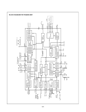
... VERTICAL BLANK VERTICAL POSITION VERTICAL SIZE, VOVSCN HUNLOCK 17 HUNLOCK OUTPUT 19 SDA SCL 18 VCC 9.2 to 16V 10 PGND 7 SGND 25 I2C-BUS RECEIVER SUPPLY AND REFERENCE PRETECTION AND SOFT START 2 I2C-BUS REGISTERS COINCIDENCE DETECTOR FREQUENCY DETECTOR TV MODE TDA4857 X-RAY PRETECTION FOCUS VERTICAL B+ CONTROL 20 i.c 32 FOCUS 6 BDRV 4 BSENS 3 BOP 5 BIN X-RAY B+ CONTOL A P P L I C AT I O N HSYNC (TTL level) (video) 15 H/C SYNC INPUT...
... VERTICAL BLANK VERTICAL POSITION VERTICAL SIZE, VOVSCN HUNLOCK 17 HUNLOCK OUTPUT 19 SDA SCL 18 VCC 9.2 to 16V 10 PGND 7 SGND 25 I2C-BUS RECEIVER SUPPLY AND REFERENCE PRETECTION AND SOFT START 2 I2C-BUS REGISTERS COINCIDENCE DETECTOR FREQUENCY DETECTOR TV MODE TDA4857 X-RAY PRETECTION FOCUS VERTICAL B+ CONTROL 20 i.c 32 FOCUS 6 BDRV 4 BSENS 3 BOP 5 BIN X-RAY B+ CONTOL A P P L I C AT I O N HSYNC (TTL level) (video) 15 H/C SYNC INPUT...

Service Manual
Page 37
CONTROL BOARD (Solder Side) 3. MAIN BOARD (Component Side) 4. MAIN BOARD (Solder Side) - 38 - - 39 - CONTROL BOARD (Component Side) PRINTED CIRCUIT BOARD 2. 1.
CONTROL BOARD (Solder Side) 3. MAIN BOARD (Component Side) 4. MAIN BOARD (Solder Side) - 38 - - 39 - CONTROL BOARD (Component Side) PRINTED CIRCUIT BOARD 2. 1.


