Owners Manual
Page 1
... before operating your dealer when you require service. LCD TV MODELS: 32LC2D 32LC2DU 37LC2D 42LC2D PLASMA TV MODELS: 42PC3D 42PC3DC 42PC3DV 50PC3D 60PC1D 60PC1DC OWNER'S MANUAL Internet Home Page : http://www.lge.com http://www.lg.ca http://www.lgcommercial.com ENERGYSTAR is a set of the set . Environmental Protection Agency(EPA). Record model number and serial number of power-saving guidelines issued by the U.S. A.,Inc. has determined that this...
... before operating your dealer when you require service. LCD TV MODELS: 32LC2D 32LC2DU 37LC2D 42LC2D PLASMA TV MODELS: 42PC3D 42PC3DC 42PC3DV 50PC3D 60PC1D 60PC1DC OWNER'S MANUAL Internet Home Page : http://www.lge.com http://www.lg.ca http://www.lgcommercial.com ENERGYSTAR is a set of the set . Environmental Protection Agency(EPA). Record model number and serial number of power-saving guidelines issued by the U.S. A.,Inc. has determined that this...
Owners Manual
Page 4
... the monitor's performance. - Use only with a cart, stand, tripod, bracket, or table specified by an authorized servicer. DISCONNECTING DEVICE FROM MAINS Main plug is , a single outlet circuit which powers only that appliance and has no adverse effect on the screen. Overloaded wall outlets, loose or damaged wall outlets, extension cords, frayed power cords, or damaged or cracked wire insulation are dangerous. b. Any of this owner's manual to...
... the monitor's performance. - Use only with a cart, stand, tripod, bracket, or table specified by an authorized servicer. DISCONNECTING DEVICE FROM MAINS Main plug is , a single outlet circuit which powers only that appliance and has no adverse effect on the screen. Overloaded wall outlets, loose or damaged wall outlets, extension cords, frayed power cords, or damaged or cracked wire insulation are dangerous. b. Any of this owner's manual to...
Owners Manual
Page 5
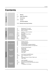
... Pedestal Installation Basic Connection Antenna or Cable Connection VCR Setup External AV Source Setup DVD Setup HDSTB Setup AV Out Setup Digital Audio Output PC Setup 29 29 29 29 30 31 31 32 33 33 34 35 35~36 37 38 39 40 41 41~42 43 43 Turning on the TV Volume Adjustment Channel Selection On Screen Menus Language Selection On Screen Menus Selection and Adjustment EZ Scan (Channel Search) Manual Scan Channel Edit DTV Signal Strength Input Source Input Label Auto Picture Control(EZ Picture) Color Temperature Control...
... Pedestal Installation Basic Connection Antenna or Cable Connection VCR Setup External AV Source Setup DVD Setup HDSTB Setup AV Out Setup Digital Audio Output PC Setup 29 29 29 29 30 31 31 32 33 33 34 35 35~36 37 38 39 40 41 41~42 43 43 Turning on the TV Volume Adjustment Channel Selection On Screen Menus Language Selection On Screen Menus Selection and Adjustment EZ Scan (Channel Search) Manual Scan Channel Edit DTV Signal Strength Input Source Input Label Auto Picture Control(EZ Picture) Color Temperature Control...
Owners Manual
Page 11
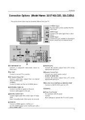
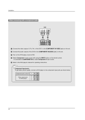
...PC) VIDEO AUDIO 5 AV OUT AV IN 1 COMPONENT IN 4 HDMI IN 2 8 VIDEO AUDIO 2 ANTENNA/ 1(DVI) OPTICAL CABLE IN RS-232C IN (CONTROL & SERVICE) DIGITAL AUDIO OUT S-VIDEO VIDEO (MONO) AUDIO 3 AV OUT 1 COMPONENT IN Connect a component these jacks. 9 video/audio device toS-VIDEO VIDEO AV IN 1 7 RGB IN (PC) ( ) AUDIO Connect the monitor output from a PC to the appropriate input port. 2 AV OUT Connect a second TV or monitor. 3 AV (Audio/Video) IN 1 Connect audio/video output from a video device. Connect cable signals to these ports do not work. 8 Remote Control Port Connect...
...PC) VIDEO AUDIO 5 AV OUT AV IN 1 COMPONENT IN 4 HDMI IN 2 8 VIDEO AUDIO 2 ANTENNA/ 1(DVI) OPTICAL CABLE IN RS-232C IN (CONTROL & SERVICE) DIGITAL AUDIO OUT S-VIDEO VIDEO (MONO) AUDIO 3 AV OUT 1 COMPONENT IN Connect a component these jacks. 9 video/audio device toS-VIDEO VIDEO AV IN 1 7 RGB IN (PC) ( ) AUDIO Connect the monitor output from a PC to the appropriate input port. 2 AV OUT Connect a second TV or monitor. 3 AV (Audio/Video) IN 1 Connect audio/video output from a video device. Connect cable signals to these ports do not work. 8 Remote Control Port Connect...
Owners Manual
Page 19
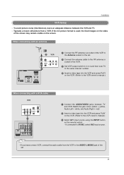
... 1 Connect the AUDIO/VIDEO jacks between the VCR and TV. - the fixed images on the screen. Match the jack colors (Video = yellow, Audio Left = white, and Audio Right = red) 2 Insert a video tape into the VCR and press PLAY on the remote control. - VIDEO AUDIO OPTICAL DIGITAL AUDIO VIDEOS-VIDEO OUT ( ) VIDAEUODIO AUDIO 19 COMPONENT IN AV OUT AV IN 1 COMPONENT IN AV OUT A Typically a frozen still picture from the VCR to the VCR owner's manual.) 3 Select AV1 input source using the INPUT button...
... 1 Connect the AUDIO/VIDEO jacks between the VCR and TV. - the fixed images on the screen. Match the jack colors (Video = yellow, Audio Left = white, and Audio Right = red) 2 Insert a video tape into the VCR and press PLAY on the remote control. - VIDEO AUDIO OPTICAL DIGITAL AUDIO VIDEOS-VIDEO OUT ( ) VIDAEUODIO AUDIO 19 COMPONENT IN AV OUT AV IN 1 COMPONENT IN AV OUT A Typically a frozen still picture from the VCR to the VCR owner's manual.) 3 Select AV1 input source using the INPUT button...
Owners Manual
Page 20
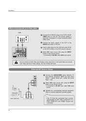
.... External AV Source Setup Camcorder Video Game Set 1 L AUDIO R VIDEO 1 Connect the AUDIO/VIDEO jacks between TV and external equipment. Match the jack colors (Video = yellow, Audio Left = white, and Audio Right = red). 2 Select AV2 input source with using the INPUT button on the set . 3 Insert a video tape into the VCR and press PLAY on the VCR. (Refer to the VCR owner's manual.) 4 Select AV1 input source with using the INPUT button on the remote control. - In the event that you connect both Video and S-Video at the same time.
.... External AV Source Setup Camcorder Video Game Set 1 L AUDIO R VIDEO 1 Connect the AUDIO/VIDEO jacks between TV and external equipment. Match the jack colors (Video = yellow, Audio Left = white, and Audio Right = red). 2 Select AV2 input source with using the INPUT button on the set . 3 Insert a video tape into the VCR and press PLAY on the VCR. (Refer to the VCR owner's manual.) 4 Select AV1 input source with using the INPUT button on the remote control. - In the event that you connect both Video and S-Video at the same time.
Owners Manual
Page 21
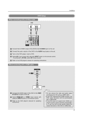
... the DVD supports Auto HDMI function, the DVD output resolution will be automatically set to 1280x720p. • If the DVD does not support Auto HDMI, you need to set . 3 Turn on the DVD player, insert a DVD. 4 Select AV1 input source with using the INPUT button on the remote control. 3 Refer to the DVD player's manual for operating instructions. If connected to AV IN2, select AV 2 input source. 5 Refer to 1280x720p. 21 VIDEO AUDIO COMPONENT IN AV OUT AV IN 1 OPTICAL DIGITAL AUDIO OUT S-VIDEO VIDEO ( ) AUDIO • TV can receive the video and audio signal...
... the DVD supports Auto HDMI function, the DVD output resolution will be automatically set to 1280x720p. • If the DVD does not support Auto HDMI, you need to set . 3 Turn on the DVD player, insert a DVD. 4 Select AV1 input source with using the INPUT button on the remote control. 3 Refer to the DVD player's manual for operating instructions. If connected to AV IN2, select AV 2 input source. 5 Refer to 1280x720p. 21 VIDEO AUDIO COMPONENT IN AV OUT AV IN 1 OPTICAL DIGITAL AUDIO OUT S-VIDEO VIDEO ( ) AUDIO • TV can receive the video and audio signal...
Owners Manual
Page 22
...VIDEO AUDIO To get better picture quality, connect a DVD player to the DVD player's manual for operating instructions. Component ports on the TV Video output ports on the remote control. - If connected to COMPONENT IN 2, select Component 2 input source. 5 Refer to the component input ports as shown below. Installation When connecting with a component cable DVD B R (R) AUDIO (L) 1 2 VIDEO AUDIO ANTENNA/ CABLE IN HDMI / DVI IN COMPONENT IN 1 Connect the video outputs (Y, PB, PR) of the DVD to the COMPONENT IN VIDEO jacks on the set. 2 Connect the audio outputs of the DVD...
...VIDEO AUDIO To get better picture quality, connect a DVD player to the DVD player's manual for operating instructions. Component ports on the TV Video output ports on the remote control. - If connected to COMPONENT IN 2, select Component 2 input source. 5 Refer to the component input ports as shown below. Installation When connecting with a component cable DVD B R (R) AUDIO (L) 1 2 VIDEO AUDIO ANTENNA/ CABLE IN HDMI / DVI IN COMPONENT IN 1 Connect the video outputs (Y, PB, PR) of the DVD to the COMPONENT IN VIDEO jacks on the set. 2 Connect the audio outputs of the DVD...
Owners Manual
Page 23
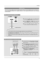
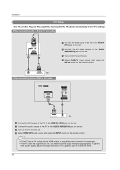
... TV can receive the video and audio signal simultaneously using the INPUT button on the remote control. 3 Turn on the remote control. - To get the best picture quality, adjust the output resolution of the digital set-top box will be automatically set to 1280x720p. • If the digital set-top box does not support Auto HDMI, you do receive Digital signals from a digital set -top box. COMPONENT IN AV OUT AV IN 1 RGB IN (PC) REMORTEGBAIUNDIO IN CONTROL IN (RGB/DVI) RS-232C IN (CONTROL & SERVICE) OPTICAL DIGITAL AUDIO OUT S-VIDEO VIDEO (MONO) AUDIO SERVICE HDMI / DVI...
... TV can receive the video and audio signal simultaneously using the INPUT button on the remote control. 3 Turn on the remote control. - To get the best picture quality, adjust the output resolution of the digital set-top box will be automatically set to 1280x720p. • If the digital set-top box does not support Auto HDMI, you do receive Digital signals from a digital set -top box. COMPONENT IN AV OUT AV IN 1 RGB IN (PC) REMORTEGBAIUNDIO IN CONTROL IN (RGB/DVI) RS-232C IN (CONTROL & SERVICE) OPTICAL DIGITAL AUDIO OUT S-VIDEO VIDEO (MONO) AUDIO SERVICE HDMI / DVI...
Owners Manual
Page 24
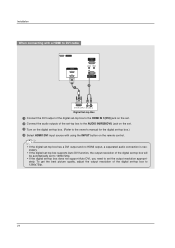
... INPUT button on the digital set-top box. (Refer to 1280x720p. 24 RGB IN 3 Turn on the remote control. To get the best picture quality, adjust the output resolution of the digital set-top box will be automatically set to 1280x720p. • If the digital set-top box does not support Auto DVI, you need to set -top box to the owner's manual for the d(PCi)gital set . RS-232C IN (CONTROL & SERVICE) • If the digital set-top box has a DVI output and no HDMI output, a separated audio connection...
... INPUT button on the digital set-top box. (Refer to 1280x720p. 24 RGB IN 3 Turn on the remote control. To get the best picture quality, adjust the output resolution of the digital set-top box will be automatically set to 1280x720p. • If the digital set-top box does not support Auto DVI, you need to set -top box to the owner's manual for the d(PCi)gital set . RS-232C IN (CONTROL & SERVICE) • If the digital set-top box has a DVI output and no HDMI output, a separated audio connection...
Owners Manual
Page 25
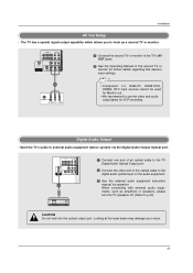
...) AUDIO 1/2 1 Connect one end of an optical cable to the TV Digital Audio Optical Output port. 2 Connect the other end of the second TV or monitor for further details regarding that device's input settings. 1/2 S-VIDEO IN (R) AUDIO (L) VIDEO • Component 1-2, RGB-PC, HDMI1/DVI, HDMI2, DTV input sources cannot be used for Monitor out. • We recommend to use the video and audio output jacks for operation. Digital Audio Output - Send the TV's audio to the digital audio optical input on the audio equipment. 3 See the external audio equipment instruction manual...
...) AUDIO 1/2 1 Connect one end of an optical cable to the TV Digital Audio Optical Output port. 2 Connect the other end of the second TV or monitor for further details regarding that device's input settings. 1/2 S-VIDEO IN (R) AUDIO (L) VIDEO • Component 1-2, RGB-PC, HDMI1/DVI, HDMI2, DTV input sources cannot be used for Monitor out. • We recommend to use the video and audio output jacks for operation. Digital Audio Output - Send the TV's audio to the digital audio optical input on the audio equipment. 3 See the external audio equipment instruction manual...
Owners Manual
Page 26
... support Auto DVI, you need to set . 4 Select HDMI1/DVI input source with using the INPUT button on the set. 2 Connect the PC audio outputs to 1024x768, 60Hz. (CONTROL&SERVICE) 26 When connecting with a D-sub 15 pin cable RGB IN (PC) AUDIO IN REMOTE (RGB/DVI) CONTROL IN RS-232C IN (CONTROL & SERVICE) 2 1 1 Connect the RGB output of PC graphics card to the AUDIO IN(RGB/DVI) jack on the set. 3 Turn on the PC and the set. 4 Select RGB-PC input source with a HDMI to DVI cable SERVICE HDMI...
... support Auto DVI, you need to set . 4 Select HDMI1/DVI input source with using the INPUT button on the set. 2 Connect the PC audio outputs to 1024x768, 60Hz. (CONTROL&SERVICE) 26 When connecting with a D-sub 15 pin cable RGB IN (PC) AUDIO IN REMOTE (RGB/DVI) CONTROL IN RS-232C IN (CONTROL & SERVICE) 2 1 1 Connect the RGB output of PC graphics card to the AUDIO IN(RGB/DVI) jack on the set. 3 Turn on the PC and the set. 4 Select RGB-PC input source with a HDMI to DVI cable SERVICE HDMI...
Owners Manual
Page 27
... of TV SET and contact an PC graphics card service center. 3. Avoid keeping a fixed image on the menu until the picture is not supported TV SET output in HDMI/DVI Input. In case that Video Resolution is clear. There may not fit to Screen.Press the ADJUST button to adjust the screen Position of the PC graphic card can not be noise associated with HDMI/DVI Input, output TV SET Resolution (480p, 720p, 1080i) and TV SET Display fit EIA/CEA-861-B Specification to...
... of TV SET and contact an PC graphics card service center. 3. Avoid keeping a fixed image on the menu until the picture is not supported TV SET output in HDMI/DVI Input. In case that Video Resolution is clear. There may not fit to Screen.Press the ADJUST button to adjust the screen Position of the PC graphic card can not be noise associated with HDMI/DVI Input, output TV SET Resolution (480p, 720p, 1080i) and TV SET Display fit EIA/CEA-861-B Specification to...
Owners Manual
Page 29
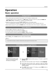
Select the viewing source by pressing the MUTE or VOL D / E button. When finished using TV INPUT, INPUT button on the remote control. The menus can cancel this function by using the TV, press the POWER button on -screen menus will be shown in the selected language. Channel Selection Press the CH D / E or NUMBER buttons to select a channel number. • If you want to the previous menu. 29 First, connect power cord correctly. The TV reverts to...
Select the viewing source by pressing the MUTE or VOL D / E button. When finished using TV INPUT, INPUT button on the remote control. The menus can cancel this function by using the TV, press the POWER button on -screen menus will be shown in the selected language. Channel Selection Press the CH D / E or NUMBER buttons to select a channel number. • If you want to the previous menu. 29 First, connect power cord correctly. The TV reverts to...
Owners Manual
Page 31
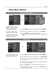
... the channel number. 6 Press EXIT button to return to TV viewing or press MENU button to return to begin the channel search. A password is required to gain access to Manual Scan menu if the Lock System is turned on the channel list. - TV Ch.20 0 channel(s) found Press to delete the channel. - Next MENU Previous - D E TV G 2 TV 2-0 Press to stop the current scan and start DIGITAL ANTENNA channel scan. Setup Menu Options Operation EZ Scan (Channel Search) EZ Scan Manual Scan Channel Edit DTV Signal Input Source Input Label Set...
... the channel number. 6 Press EXIT button to return to TV viewing or press MENU button to return to begin the channel search. A password is required to gain access to Manual Scan menu if the Lock System is turned on the channel list. - TV Ch.20 0 channel(s) found Press to delete the channel. - Next MENU Previous - D E TV G 2 TV 2-0 Press to stop the current scan and start DIGITAL ANTENNA channel scan. Setup Menu Options Operation EZ Scan (Channel Search) EZ Scan Manual Scan Channel Edit DTV Signal Input Source Input Label Set...
Owners Manual
Page 51
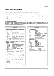
... up) • 16 ans+ (16 years and up ) • G (General programming. To use the Movie Rating System (MPAA) only. Set ratings and categories to block specific channels, ratings and other viewing sources. sexual dialogue (applies to TV-PG, TV14, TV-MA) • Sex- The default setting is used to be blocked. Enable the lock V-Chip rating and categories Rating guidelines are provided by...
... up) • 16 ans+ (16 years and up ) • G (General programming. To use the Movie Rating System (MPAA) only. Set ratings and categories to block specific channels, ratings and other viewing sources. sexual dialogue (applies to TV-PG, TV14, TV-MA) • Sex- The default setting is used to be blocked. Enable the lock V-Chip rating and categories Rating guidelines are provided by...
Owners Manual
Page 54
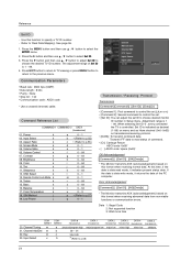
Use this format when receiving abnormal data from non-viable functions or communication errors. Press EXIT button to return to TV viewing or press MENU button to return to specify a TV ID number. - Screen Mute k 05. Volume Control k 07. Color k 10. OSD Select k 13. Color Temperature k 18. Adjustment range is controlled. Set ID is data write mode, it indicates present status data. Data 1: Illegal Code 2: Not supported function 3: Wait more time COM- EZ Scan Manual Scan Channel Edit...
Use this format when receiving abnormal data from non-viable functions or communication errors. Press EXIT button to return to TV viewing or press MENU button to return to specify a TV ID number. - Screen Mute k 05. Volume Control k 07. Color k 10. OSD Select k 13. Color Temperature k 18. Adjustment range is controlled. Set ID is data write mode, it indicates present status data. Data 1: Illegal Code 2: Not supported function 3: Wait more time COM- EZ Scan Manual Scan Channel Edit...
Owners Manual
Page 61
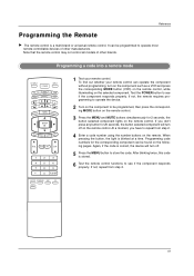
.... If not, the remote requires programming to operate the device. 2 Turn on the remote control. When pressing the button, the light is a multi-brand or universal remote control. Programming code numbers for the corresponding component can be programmed to see if the component responds properly. Reference Programming the Remote G The remote control is blinked at a time. Programming a code into a remote mode TV INPUT POWER TV AUDIO DVD MODE CABLE INPUT VCR STB BRIGHT - Again, if the code is stored. 6 Test the remote control functions to repeat...
.... If not, the remote requires programming to operate the device. 2 Turn on the remote control. When pressing the button, the light is a multi-brand or universal remote control. Programming code numbers for the corresponding component can be programmed to see if the component responds properly. Reference Programming the Remote G The remote control is blinked at a time. Programming a code into a remote mode TV INPUT POWER TV AUDIO DVD MODE CABLE INPUT VCR STB BRIGHT - Again, if the code is stored. 6 Test the remote control functions to repeat...
Owners Manual
Page 64
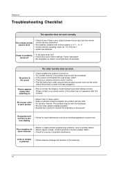
... not work normally. The problem may be with the broadcast. • Is the power cord inserted into wall power outlet? • Check your service center, if the picture has not appeared after switching on station tuned with Auto off • Is the sleep timer set : TV, VCR etc.? • Install new batteries. Please contact your antenna direction and/or location. • Test the wall power outlet, plug another channel. Poor...
... not work normally. The problem may be with the broadcast. • Is the power cord inserted into wall power outlet? • Check your service center, if the picture has not appeared after switching on station tuned with Auto off • Is the sleep timer set : TV, VCR etc.? • Install new batteries. Please contact your antenna direction and/or location. • Test the wall power outlet, plug another channel. Poor...
Owners Manual
Page 65
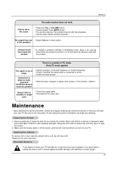
... the signal cable is connected or loose. • Check the input source. • Work the Auto configure or adjust clock, phase, or H/V position. (Option) Screen color is turned on or off and does not indicate a fault with the product. The problem may result in menu option. of time you turn on back- Be sure to wipe the screen. 2. Reference The audio function does not work. Press MUTE button. •...
... the signal cable is connected or loose. • Check the input source. • Work the Auto configure or adjust clock, phase, or H/V position. (Option) Screen color is turned on or off and does not indicate a fault with the product. The problem may result in menu option. of time you turn on back- Be sure to wipe the screen. 2. Reference The audio function does not work. Press MUTE button. •...


