
Owner's Manual (English)
Page 1
P/NO : SAC30708033 (0810-REV03) www.lgusa.com / www.lg.ca Record model number and serial number of the set . See the label attached on the back cover and quote this manual carefully before operating your dealer when you require service. LCD TV OWNER'S MANUAL 37LG50 42LG50 47LG50 52LG50 42LG50DC 47LG50DC 52LG50DC 42LG55 47LG55 Please read this information to your set . Retain it for future reference.
P/NO : SAC30708033 (0810-REV03) www.lgusa.com / www.lg.ca Record model number and serial number of the set . See the label attached on the back cover and quote this manual carefully before operating your dealer when you require service. LCD TV OWNER'S MANUAL 37LG50 42LG50 47LG50 52LG50 42LG50DC 47LG50DC 52LG50DC 42LG55 47LG55 Please read this information to your set . Retain it for future reference.
Owner's Manual (English)
Page 2
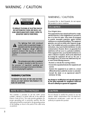
...attention to the point of the National Electric Code (U.S.A.). NO USER SERVICEABLE PARTS INSIDE. Consult the dealer or an experienced radio/TV technician for proper grounding and, in any way without written authorization from that the cable ground shall be determined by the party ...used in a residential installation. Any changes or modifications not expressly approved by turning the equipment off and on a circuit different from LG Electronics. FCC NOTICE Class B digital device This equipment has been tested and found to comply with the limits for compliance could ...
...attention to the point of the National Electric Code (U.S.A.). NO USER SERVICEABLE PARTS INSIDE. Consult the dealer or an experienced radio/TV technician for proper grounding and, in any way without written authorization from that the cable ground shall be determined by the party ...used in a residential installation. Any changes or modifications not expressly approved by turning the equipment off and on a circuit different from LG Electronics. FCC NOTICE Class B digital device This equipment has been tested and found to comply with the limits for compliance could ...
Owner's Manual (English)
Page 4
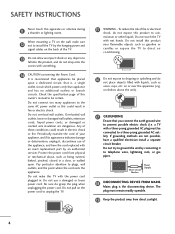
...If grounding methods are dangerous. SAFETY INSTRUCTIONS 11 Never touch this product to rain, moisture or other liquids. Check the specification page of the TV. 13 Do not allow an impact shock or any objects to plugs, wall outlets, and the point where the cord exits the appliance. Overloaded... 19 Keep the product away from physical or mechanical abuse, such as vases, cups, etc. Do not pull on the wall, make the TV with liquids, such as being twisted, kinked, pinched, closed in fire or electric shock. Short-circuit Breaker Power Supply 18 DISCONNECTING DEVICE FROM MAINS...
...If grounding methods are dangerous. SAFETY INSTRUCTIONS 11 Never touch this product to rain, moisture or other liquids. Check the specification page of the TV. 13 Do not allow an impact shock or any objects to plugs, wall outlets, and the point where the cord exits the appliance. Overloaded... 19 Keep the product away from physical or mechanical abuse, such as vases, cups, etc. Do not pull on the wall, make the TV with liquids, such as being twisted, kinked, pinched, closed in fire or electric shock. Short-circuit Breaker Power Supply 18 DISCONNECTING DEVICE FROM MAINS...

Owner's Manual (English)
Page 5
An outdoor antenna system should not be located in the vicinity of overhead power lines or other liquids directly on the TV as alcohol, thinners or benzene. 5 Section 810 of antenna discharge unit, connection to grounding electrodes and requirements for the grounding electrode. It may occur. ... System (NEC Art 250, Part H) 21 Cleaning When cleaning, unplug the power cord and scrub gently with cloth or other odors coming from the TV or hear strange sounds, unplug the power cord contact an authorized service center. 25 Do not press strongly upon the panel with chemicals such as...
An outdoor antenna system should not be located in the vicinity of overhead power lines or other liquids directly on the TV as alcohol, thinners or benzene. 5 Section 810 of antenna discharge unit, connection to grounding electrodes and requirements for the grounding electrode. It may occur. ... System (NEC Art 250, Part H) 21 Cleaning When cleaning, unplug the power cord and scrub gently with cloth or other odors coming from the TV or hear strange sounds, unplug the power cord contact an authorized service center. 25 Do not press strongly upon the panel with chemicals such as...
Owner's Manual (English)
Page 6
... Manual Picture Adjustment - Picture Mode - Eye Care 64 Advanced Control - CONTENTS WARNING / CAUTION 2 SAFETY INSTRUCTIONS 3 FEATURE OF THIS TV 8 PREPARATION Accessories 9 Front Panel Information 10 Back Panel Information 11 Stand Instruction 12 VESA Wall Mounting 13 Cable Management 14 Desktop Pedestal ... Other A/V Source Setup 25 PC Setup 26 USB Connection 32 Audio Out Connection 33 WATCHING TV / CHANNEL CONTROL Remote Control Functions 34 Turning On the TV 36 Channel Selection 36 Volume Adjustment 36 Quick Menu / Favorite Channel Setup 37 Initial Setting...
... Manual Picture Adjustment - Picture Mode - Eye Care 64 Advanced Control - CONTENTS WARNING / CAUTION 2 SAFETY INSTRUCTIONS 3 FEATURE OF THIS TV 8 PREPARATION Accessories 9 Front Panel Information 10 Back Panel Information 11 Stand Instruction 12 VESA Wall Mounting 13 Cable Management 14 Desktop Pedestal ... Other A/V Source Setup 25 PC Setup 26 USB Connection 32 Audio Out Connection 33 WATCHING TV / CHANNEL CONTROL Remote Control Functions 34 Turning On the TV 36 Channel Selection 36 Volume Adjustment 36 Quick Menu / Favorite Channel Setup 37 Initial Setting...

Owner's Manual (English)
Page 7
Digital Broadcasting System Captions 79 - Caption Option 80 TIME SETTING Clock Setting - User Mode 70 Clear Voice 71 Balance 72 TV Speakers On/Off Setup 73 Audio Reset 74 Stereo/SAP Broadcast Setup 75 Audio Language 76 On-Screen Menus Language Selection 77 ...83 Sleep Timer Setting 84 Auto Shut-off Setting 85 PARENTAL CONTROL / RATINGS Set Password & Lock System 86 Channel Blocking 89 Movie & TV Rating 90 Downloadable Rating 95 External Input Blocking 96 Key lock 97 APPENDIX Troubleshooting 98 Maintenance 100 Product Specifications 101 Programming the Remote Control 102...
Digital Broadcasting System Captions 79 - Caption Option 80 TIME SETTING Clock Setting - User Mode 70 Clear Voice 71 Balance 72 TV Speakers On/Off Setup 73 Audio Reset 74 Stereo/SAP Broadcast Setup 75 Audio Language 76 On-Screen Menus Language Selection 77 ...83 Sleep Timer Setting 84 Auto Shut-off Setting 85 PARENTAL CONTROL / RATINGS Set Password & Lock System 86 Channel Blocking 89 Movie & TV Rating 90 Downloadable Rating 95 External Input Blocking 96 Key lock 97 APPENDIX Troubleshooting 98 Maintenance 100 Product Specifications 101 Programming the Remote Control 102...
Owner's Manual (English)
Page 8
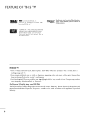
.... Do not dispose of this product contains a small amount of this product must be made through the ISFccc mode. FOR LCD TV I Avoid touching the LCD screen or holding your finger(s) against it is incorporated under license from SRS Labs, Inc. Please contact your local authority.... 8 Disposal of mercury. Detailed calibration requires a licensed technician. On Disposal (Only Hg lamp used LCD TV) The fluorescent lamp used in accordance to the touch, there may produce some temporary distortion effects on the screen, appearing as tiny red,...
.... Do not dispose of this product contains a small amount of this product must be made through the ISFccc mode. FOR LCD TV I Avoid touching the LCD screen or holding your finger(s) against it is incorporated under license from SRS Labs, Inc. Please contact your local authority.... 8 Disposal of mercury. Detailed calibration requires a licensed technician. On Disposal (Only Hg lamp used LCD TV) The fluorescent lamp used in accordance to the touch, there may produce some temporary distortion effects on the screen, appearing as tiny red,...
Owner's Manual (English)
Page 9
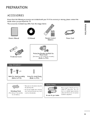
If an accessory is not available scratch or discoloration. RETURN TV Q. for stand fixing (Refer to P.12) (Refer to P.15) * Wipe spots on the exterior only with the polishing cloth. * Do not wipe roughly when removing ... VGA (D-sub 15 pin cable) PC connection, the user must use shielded signal interface cables with your TV. The accessories included may cause (This feature is missing, please contact the dealer where you purchased the TV. MESNTUB MENU POWER DVD INPVUTCR ENTER VOL FAV AV MODE 1 4 MUTE 2 7 5 3 8 6 0 9 FLASHBK CH P A G E 1.5V 1.5V Copyright...
If an accessory is not available scratch or discoloration. RETURN TV Q. for stand fixing (Refer to P.12) (Refer to P.15) * Wipe spots on the exterior only with the polishing cloth. * Do not wipe roughly when removing ... VGA (D-sub 15 pin cable) PC connection, the user must use shielded signal interface cables with your TV. The accessories included may cause (This feature is missing, please contact the dealer where you purchased the TV. MESNTUB MENU POWER DVD INPVUTCR ENTER VOL FAV AV MODE 1 4 MUTE 2 7 5 3 8 6 0 9 FLASHBK CH P A G E 1.5V 1.5V Copyright...

Owner's Manual (English)
Page 10
... a protection tape attached, remove the tape. I Image shown may differ from your TV, use it). And then wipe the TV with a cloth (If a polishing cloth is switched on. (Can be adjusted using Power Indicator in standby mode. G p.67) Remote Control Sensor POWER Button CH CHANNEL ( , ) ... Adjusts picture according to the surrounding conditions Power/Standby Indicator Illuminates red in the OPTION menu. Illuminates blue when the set is included with your TV.
... a protection tape attached, remove the tape. I Image shown may differ from your TV, use it). And then wipe the TV with a cloth (If a polishing cloth is switched on. (Can be adjusted using Power Indicator in standby mode. G p.67) Remote Control Sensor POWER Button CH CHANNEL ( , ) ... Adjusts picture according to the surrounding conditions Power/Standby Indicator Illuminates red in the OPTION menu. Illuminates blue when the set is included with your TV.
Owner's Manual (English)
Page 11
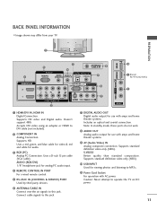
... air signals to MP3s. 11 Power Cord Socket For operation with AC power. R R BACK PANEL INFORMATION I Image shown may differ from your TV. Uses a D-sub 15 pin cable (VGA cable). Supports standard definition video only (480i). Connect cable signals to DVI cable (not included)....IN 3 USB IN 3 5 ANTENNA/ CABLE IN 6 4 RGB IN DIGITAL AUDIO OUT 1 RGB(PC) AUDIO REMOTE (RGB/DVI) CONTROL IN OPTICAL COAXIAL 7 10 1 (Except 42/47/52LG50DC) HDMI/DVI IN 2 2 1 1 RS-232C IN AUDIO OUT (CONTROL & SERVICE) 8 AV IN 1 VIDEO AUDIO COMPONENT IN 2 S-VIDEO VIDEO (MONO) AUDIO 9 ( ) 9...
... air signals to MP3s. 11 Power Cord Socket For operation with AC power. R R BACK PANEL INFORMATION I Image shown may differ from your TV. Uses a D-sub 15 pin cable (VGA cable). Supports standard definition video only (480i). Connect cable signals to DVI cable (not included)....IN 3 USB IN 3 5 ANTENNA/ CABLE IN 6 4 RGB IN DIGITAL AUDIO OUT 1 RGB(PC) AUDIO REMOTE (RGB/DVI) CONTROL IN OPTICAL COAXIAL 7 10 1 (Except 42/47/52LG50DC) HDMI/DVI IN 2 2 1 1 RS-232C IN AUDIO OUT (CONTROL & SERVICE) 8 AV IN 1 VIDEO AUDIO COMPONENT IN 2 S-VIDEO VIDEO (MONO) AUDIO 9 ( ) 9...
Owner's Manual (English)
Page 12
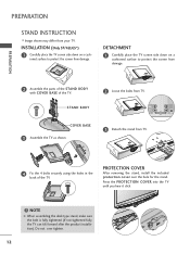
... using the holes in the back of the TV. INSTALLATION (Only 37/42LG5*) 1 Carefully place the TV screen side down on a cush- COVER BASE 3 Assemble the TV as shown. 3 Detach the stand from TV. Press the PROTECTION COVER into the TV until you hear it click. ! PROTECTION COVER... the bolt is fully tightened (If not tightened fully, the TV can tilt forward after the product installation). DETACHMENT 1 Carefully place the TV screen side down on a cushioned surface to protect the screen from your TV. PREPARATION PREPARATION STAND INSTRUCTION I Image shown may differ from damage...
... using the holes in the back of the TV. INSTALLATION (Only 37/42LG5*) 1 Carefully place the TV screen side down on a cush- COVER BASE 3 Assemble the TV as shown. 3 Detach the stand from TV. Press the PROTECTION COVER into the TV until you hear it click. ! PROTECTION COVER... the bolt is fully tightened (If not tightened fully, the TV can tilt forward after the product installation). DETACHMENT 1 Carefully place the TV screen side down on a cushioned surface to protect the screen from your TV. PREPARATION PREPARATION STAND INSTRUCTION I Image shown may differ from damage...
Owner's Manual (English)
Page 13
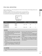
LG recommends that you use fasten the screws too strongly, this may cause damage to the inside to a fall and result in severe personal injury. A B Product LCD TV Model 37LG5* 42LG5* 47LG5* 52LG5* VESA (A * B) Standard Screw Quantity 200 * 200 M6 4 800 * 400 M6 4 ! G Do not use screws...use screws longer then the standard dimension, as they may damage the TV or cause the TV to the TV. G For wall mounts that do not comply with the VESA standard screw specifications, the length of accidents. LG is turned on. We recommend that wall mounting be performed by a ...
LG recommends that you use fasten the screws too strongly, this may cause damage to the inside to a fall and result in severe personal injury. A B Product LCD TV Model 37LG5* 42LG5* 47LG5* 52LG5* VESA (A * B) Standard Screw Quantity 200 * 200 M6 4 800 * 400 M6 4 ! G Do not use screws...use screws longer then the standard dimension, as they may damage the TV or cause the TV to the TV. G For wall mounts that do not comply with the VESA standard screw specifications, the length of accidents. LG is turned on. We recommend that wall mounting be performed by a ...
Owner's Manual (English)
Page 14
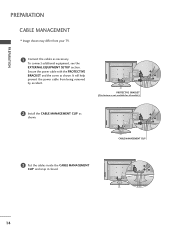
It will help prevent the power cable from your TV. 1 Connect the cables as necessary. PREPARATION PREPARATION CABLE MANAGEMENT I Image shown may differ from being removed by accident. PROTECTIVE BRACKET (This feature is not available for all models.) 2 Install the CABLE MANAGEMENT CLIP as shown. CABLE MANAGEMENT CLIP 3 Put the cables inside the CABLE MANAGEMENT CLIP and snap it closed. 14 To connect additional equipment, see the EXTERNAL EQUIPMENT SETUP section. Secure the power cable with the PROTECTIVE BRACKET and the screw as shown.
It will help prevent the power cable from your TV. 1 Connect the cables as necessary. PREPARATION PREPARATION CABLE MANAGEMENT I Image shown may differ from being removed by accident. PROTECTIVE BRACKET (This feature is not available for all models.) 2 Install the CABLE MANAGEMENT CLIP as shown. CABLE MANAGEMENT CLIP 3 Put the cables inside the CABLE MANAGEMENT CLIP and snap it closed. 14 To connect additional equipment, see the EXTERNAL EQUIPMENT SETUP section. Secure the power cable with the PROTECTIVE BRACKET and the screw as shown.
Owner's Manual (English)
Page 15
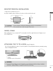
...the machine may differ from your viewing position. G Do not mount near or above any type of the product) Desk WARNING G To prevent TV from the wall. 4 inches 4 inches 4 inches 4 inches CAUTION G Ensure adequate ventilation by 20 degrees to the floor/wall per installation ...instructions. For proper ventilation, allow a clearance of 4 inches on all four sides from falling over, the TV should be pulled in a forward/backward direction, potentially causing injury or damaging the product. PREPARATION DESKTOP PEDESTAL INSTALLATION I Image shown may ...
...the machine may differ from your viewing position. G Do not mount near or above any type of the product) Desk WARNING G To prevent TV from the wall. 4 inches 4 inches 4 inches 4 inches CAUTION G Ensure adequate ventilation by 20 degrees to the floor/wall per installation ...instructions. For proper ventilation, allow a clearance of 4 inches on all four sides from falling over, the TV should be pulled in a forward/backward direction, potentially causing injury or damaging the product. PREPARATION DESKTOP PEDESTAL INSTALLATION I Image shown may ...
Owner's Manual (English)
Page 16
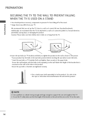
... from your product has the bolts in the eye-bolts position before inserting the eye-bolts, loosen the bolts. * Insert the eye-bolts or TV brackets/bolts and tighten them securely in a forward direction, potentially causing injury or damaging the product. Additionally, we recommend that the height of the... it becomes horizontal between the wall and the product. ! Ensure the eye-bolts or brackets are the same. 16 I Insert the eye-bolts (or TV brackets and bolts) to tighten the product to the holes in the product. We recommend that children don't climb on the wall to the wall...
... from your product has the bolts in the eye-bolts position before inserting the eye-bolts, loosen the bolts. * Insert the eye-bolts or TV brackets/bolts and tighten them securely in a forward direction, potentially causing injury or damaging the product. Additionally, we recommend that the height of the... it becomes horizontal between the wall and the product. ! Ensure the eye-bolts or brackets are the same. 16 I Insert the eye-bolts (or TV brackets and bolts) to tighten the product to the holes in the product. We recommend that children don't climb on the wall to the wall...
Owner's Manual (English)
Page 17
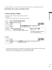
I If the antenna is not installed properly, contact your dealer for assistance. 17 Cable Cable TV Wall Jack RF Coaxial Wire (75 ohm) ( ) ANTENNA/ CABLE IN I To prevent damage do not connect to the power outlet until all connections are made ... Coaxial Wire (75 ohm) Single-family Dwellings /Houses (Connect to wall jack for outdoor antenna) Copper Wire Be careful not to be split for two TV's, install a 2-Way Signal Splitter. ( ) I If the antenna needs to bend the copper wire when connecting the antenna. 2. ANTENNA OR CABLE CONNECTION R 1. PREPARATION I To improve the...
I If the antenna is not installed properly, contact your dealer for assistance. 17 Cable Cable TV Wall Jack RF Coaxial Wire (75 ohm) ( ) ANTENNA/ CABLE IN I To prevent damage do not connect to the power outlet until all connections are made ... Coaxial Wire (75 ohm) Single-family Dwellings /Houses (Connect to wall jack for outdoor antenna) Copper Wire Be careful not to be split for two TV's, install a 2-Way Signal Splitter. ( ) I If the antenna needs to bend the copper wire when connecting the antenna. 2. ANTENNA OR CABLE CONNECTION R 1. PREPARATION I To improve the...
Owner's Manual (English)
Page 18
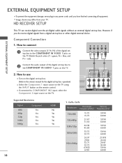
EXTERNAL EQUIPMENT SETUP EXTERNAL EQUIPMENT SETUP I Image shown may differ from a digital set-top box or other digital external device. HD RECEIVER SETUP This TV can receive digital over-the-air/digital cable signals without an external digital set -top box. Component Connection 1. Y PB PR L R 1 ... and PR = red). 2 Connect the audio output of the digital settop box to COMPONENT IN2 input, select the Component 2 input source on the TV. 2. However, if you have finished connecting all equipment. How to connect 1 Connect the video outputs (Y, PB, PR) of the digital set-top ...
EXTERNAL EQUIPMENT SETUP EXTERNAL EQUIPMENT SETUP I Image shown may differ from a digital set-top box or other digital external device. HD RECEIVER SETUP This TV can receive digital over-the-air/digital cable signals without an external digital set -top box. Component Connection 1. Y PB PR L R 1 ... and PR = red). 2 Connect the audio output of the digital settop box to COMPONENT IN2 input, select the Component 2 input source on the TV. 2. However, if you have finished connecting all equipment. How to connect 1 Connect the video outputs (Y, PB, PR) of the digital set-top ...

Owner's Manual (English)
Page 19
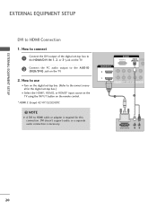
HDMI supports both audio and video. 2. How to HDMI/DVI IN1, 2, or 3* jack on the remote control. * HDMI 3: Except 42/47/52LG50DC HDMI-DTV Resolution Horizontal Vertical Frequency(KHz) Frequency(Hz) 720x480p 1280x720p 1920x1080i 1920x1080p 31.47 31.50 44.96 45.00 33.72 33.75 ...-top box. (Refer to the owner's manual for the digital set -top box to use I Select the HDMI1, HDMI2, or HDMI3* input source on the TV using the INPUT button on the TV. 2 No separate audio connection is necessary.
HDMI supports both audio and video. 2. How to HDMI/DVI IN1, 2, or 3* jack on the remote control. * HDMI 3: Except 42/47/52LG50DC HDMI-DTV Resolution Horizontal Vertical Frequency(KHz) Frequency(Hz) 720x480p 1280x720p 1920x1080i 1920x1080p 31.47 31.50 44.96 45.00 33.72 33.75 ...-top box. (Refer to the owner's manual for the digital set -top box to use I Select the HDMI1, HDMI2, or HDMI3* input source on the TV using the INPUT button on the TV. 2 No separate audio connection is necessary.
Owner's Manual (English)
Page 20
EXTERNAL EQUIPMENT SETUP EXTERNAL EQUIPMENT SETUP DVI to the A U D I Select the HDMI1, HDMI2, or HDMI3* input source on the TV using the INPUT button on the remote control. * HDMI 3: Except 42/47/52LG50DC ! RGB IN RGB(PC) AUDIO REMO (RGB/DVI) CONTRO HDMI/DVI IN 2 1 2 Y 1 PB PR L R VIDEO AUDIO COMPONENT IN 1 2 DVI-...DVI doesn't support audio, so a separate audio connection is required for the digital set -top box to the HDMI/DVI IN 1, 2, or 3* jack on the TV. 2. NOTE G A DVI to connect 1 Connect the DVI output of the digital set -top box.) I O (RGB/DVI) jack on the...
EXTERNAL EQUIPMENT SETUP EXTERNAL EQUIPMENT SETUP DVI to the A U D I Select the HDMI1, HDMI2, or HDMI3* input source on the TV using the INPUT button on the remote control. * HDMI 3: Except 42/47/52LG50DC ! RGB IN RGB(PC) AUDIO REMO (RGB/DVI) CONTRO HDMI/DVI IN 2 1 2 Y 1 PB PR L R VIDEO AUDIO COMPONENT IN 1 2 DVI-...DVI doesn't support audio, so a separate audio connection is required for the digital set -top box to the HDMI/DVI IN 1, 2, or 3* jack on the TV. 2. NOTE G A DVI to connect 1 Connect the DVI output of the digital set -top box.) I O (RGB/DVI) jack on the...
Owner's Manual (English)
Page 21
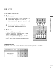
... DVD player to COMPONENT IN 2 input, select the Component 2 input source on the remote control. I Select the Component 1 input source on the TV using the INPUT button on the TV. EXTERNAL EQUIPMENT SETUP DVD SETUP Component Connection 1. Match the jack colors (Y = green, PB = blue, and PR = red). How to use... I If connected to the component input ports as shown below. I Turn on the TV. How to connect 1 Connect the video outputs (Y, PB, PR) of the DVD to the COMPONENT IN VIDEO1 jacks on the DVD player, insert a DVD. ...
... DVD player to COMPONENT IN 2 input, select the Component 2 input source on the remote control. I Select the Component 1 input source on the TV using the INPUT button on the TV. EXTERNAL EQUIPMENT SETUP DVD SETUP Component Connection 1. Match the jack colors (Y = green, PB = blue, and PR = red). How to use... I If connected to the component input ports as shown below. I Turn on the TV. How to connect 1 Connect the video outputs (Y, PB, PR) of the DVD to the COMPONENT IN VIDEO1 jacks on the DVD player, insert a DVD. ...


