
Owners Manual
Page 1
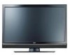
... back cover and quote this product meets the ENERGY STAR guidelines for future reference. has determined that this information to your set. A.,Inc. LCD TV PLASMA TV OWNER'S MANUAL LCD TV MODELS 37LBSD 42LBSD 47LBSD S2LBSD 47LC7DF PLASMA TV MODELS SOPY3D SOPY3DF 60PY3D 60PY3DF Please read this manual carefully before operating your dealer when you require service. Record...
... back cover and quote this product meets the ENERGY STAR guidelines for future reference. has determined that this information to your set. A.,Inc. LCD TV PLASMA TV OWNER'S MANUAL LCD TV MODELS 37LBSD 42LBSD 47LBSD S2LBSD 47LC7DF PLASMA TV MODELS SOPY3D SOPY3DF 60PY3D 60PY3DF Please read this manual carefully before operating your dealer when you require service. Record...
Owners Manual
Page 9
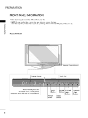
POWER Button MENU Button VOLUME (_,_) Buttons CHANNEL (T,A) Buttons 8 white when the set is included with a cloth (If a polishing cloth is switched on. ""_NOTE: If your product has a protection tape attached, remove the tape. -O And then wipe the product with your TV. PREPARATION FRONT PANELINFORMATION ,,,IHere shown may be somewhat different from your product, use it). _o rrl _o © z Plasma TV Model Program Display Remote Control Sensor Touch Pad llluminates Power/Sta nd by Indicator llluminates red in standby mode.
POWER Button MENU Button VOLUME (_,_) Buttons CHANNEL (T,A) Buttons 8 white when the set is included with a cloth (If a polishing cloth is switched on. ""_NOTE: If your product has a protection tape attached, remove the tape. -O And then wipe the product with your TV. PREPARATION FRONT PANELINFORMATION ,,,IHere shown may be somewhat different from your product, use it). _o rrl _o © z Plasma TV Model Program Display Remote Control Sensor Touch Pad llluminates Power/Sta nd by Indicator llluminates red in standby mode.
Owners Manual
Page 10
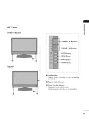
llluminates green when the set is switched on. 9 Remote Control Sensor Power/Standby Indicator Illuminates red in standby mode. LCD TV Model 37/42/47/52LB5D 47LC7DF -O _o m _o © z (A,V)Buttons (_1,1_)Buttons --ENTER Bu_on Bu_on --INPUT --POWER Bu_on Bu_on Intelligent Eye Adjusts picture according to the surrounding conditions.
llluminates green when the set is switched on. 9 Remote Control Sensor Power/Standby Indicator Illuminates red in standby mode. LCD TV Model 37/42/47/52LB5D 47LC7DF -O _o m _o © z (A,V)Buttons (_1,1_)Buttons --ENTER Bu_on Bu_on --INPUT --POWER Bu_on Bu_on Intelligent Eye Adjusts picture according to the surrounding conditions.
Owners Manual
Page 11
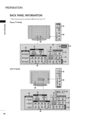
Plasma TV Model m i © z LCD TV Model 10 PREPARATION BACK PANELINFORMATION ,,,IHere shown may be somewhat different from your TV.
Plasma TV Model m i © z LCD TV Model 10 PREPARATION BACK PANELINFORMATION ,,,IHere shown may be somewhat different from your TV.
Owners Manual
Page 14
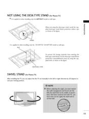
... manually to the left or right direction by using the desk-type stand, install the sup- NOT USING THE DESK-TYPESTAND (For Plasma TV) It is applied to suit your viewing position. 13 To prevent the foreign materials from entering the desk-type stand fixture, fix the desk-type ...stand fixture protection cover(additional cover) by 20 degrees to when installing only the 50/60PY3D, BOLT 50/60PY3DF model as wall-type. O z RUBBER It is applied to when installing only the 60PY3D/F model as wall-type. =O _o r_ When not using the supplied bolts as shown at the figure. plied desk...
... manually to the left or right direction by using the desk-type stand, install the sup- NOT USING THE DESK-TYPESTAND (For Plasma TV) It is applied to suit your viewing position. 13 To prevent the foreign materials from entering the desk-type stand fixture, fix the desk-type ...stand fixture protection cover(additional cover) by 20 degrees to when installing only the 50/60PY3D, BOLT 50/60PY3DF model as wall-type. O z RUBBER It is applied to when installing only the 60PY3D/F model as wall-type. =O _o r_ When not using the supplied bolts as shown at the figure. plied desk...
Owners Manual
Page 15
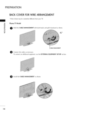
Install the CABLE MANAGEMENT as necessary. Plasma TV Model m 0 Hold the CABLE MANAGEMENT with both hands and pull it backward as shown. © z 45 ° CABLE MANAGEMENT e Connect the cables as shown. 14 To connect an additional equipment, see the EXTERNAL EQUIPMENT SETUP section. PREPARATION BACK COVER FOR WIRE ARRANGEMENT ,,,IHere shown may be somewhat different from your TV.
Install the CABLE MANAGEMENT as necessary. Plasma TV Model m 0 Hold the CABLE MANAGEMENT with both hands and pull it backward as shown. © z 45 ° CABLE MANAGEMENT e Connect the cables as shown. 14 To connect an additional equipment, see the EXTERNAL EQUIPMENT SETUP section. PREPARATION BACK COVER FOR WIRE ARRANGEMENT ,,,IHere shown may be somewhat different from your TV.
Owners Manual
Page 16
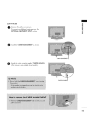
O undle the cables using the supplied TWISTER HOLDER. (This feature is not available for all models.) CABLE MANAGEMENT TWISTER HOLDER 1S LCD TV Model "O _o m O onnect the cables as necessary. _o To connect an additional equipment, see the EXTERNAL EQUIPMENT SETUP section. © z 0 Install the CABLE MANAGEMENT as shown.
O undle the cables using the supplied TWISTER HOLDER. (This feature is not available for all models.) CABLE MANAGEMENT TWISTER HOLDER 1S LCD TV Model "O _o m O onnect the cables as necessary. _o To connect an additional equipment, see the EXTERNAL EQUIPMENT SETUP section. © z 0 Install the CABLE MANAGEMENT as shown.
Owners Manual
Page 17
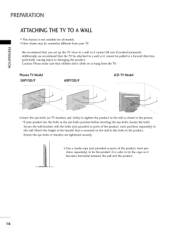
z Plasma TV Model 50PY3D/F 60PY3D/F LCD TV Model ii_i!i_i¸!iI_!Ii|!i|iIi|!l!I!||||| i_i_i_i'_iiiiliiilii!_iii_i!i!i_iiii!iiii_|i]|_i_i_ili!i!¸_|i|l|iii / iiill il_!i_ii __i !_iii! _ | _iii!iii!iiiii!_,iii Insert the eye-bolts (or TV brackets and bolts) to tighten the product to the wall as... bolts in the eye-bolts position before inserting the eye-bolts, loosen the bolts. PREPARATION ATTACHING THE TV TO A WALL ,,,IThis feature is not available for all models. ,,,iHere shown may be pulled in a forward direction, potentially causing injury or damaging the product. ...
z Plasma TV Model 50PY3D/F 60PY3D/F LCD TV Model ii_i!i_i¸!iI_!Ii|!i|iIi|!l!I!||||| i_i_i_i'_iiiiliiilii!_iii_i!i!i_iiii!iiii_|i]|_i_i_ili!i!¸_|i|l|iii / iiill il_!i_ii __i !_iii! _ | _iii!iii!iiiii!_,iii Insert the eye-bolts (or TV brackets and bolts) to tighten the product to the wall as... bolts in the eye-bolts position before inserting the eye-bolts, loosen the bolts. PREPARATION ATTACHING THE TV TO A WALL ,,,IThis feature is not available for all models. ,,,iHere shown may be pulled in a forward direction, potentially causing injury or damaging the product. ...
Owners Manual
Page 18
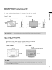
Plasma TV Model LCD TV Model 6(4070LBmSDm, 47LC7DF, S2LBSD: 800 mm) !iiii_ 400 mm 400 mm 17 Plasma TV Model LCD TV Model 4 inches I4 inches 4 inches 4 inches 4 inches 4 inches 4 inches "0 _o m _o © z 4 inches VESA WALL MOUNTING This product accepts a VESA-compliant mounting interface pad. (optional) There 4 threaded holes are available for attaching the bracket. DESKTOP PEDESTALINSTALLATION For proper ventilation, allow a clearance of 4 inches on all four sides from the wall.
Plasma TV Model LCD TV Model 6(4070LBmSDm, 47LC7DF, S2LBSD: 800 mm) !iiii_ 400 mm 400 mm 17 Plasma TV Model LCD TV Model 4 inches I4 inches 4 inches 4 inches 4 inches 4 inches 4 inches "0 _o m _o © z 4 inches VESA WALL MOUNTING This product accepts a VESA-compliant mounting interface pad. (optional) There 4 threaded holes are available for attaching the bracket. DESKTOP PEDESTALINSTALLATION For proper ventilation, allow a clearance of 4 inches on all four sides from the wall.
Owners Manual
Page 20
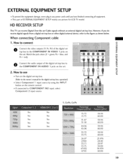
...connected to z the COMPONENT IN AUDIO 1 jacks on > the set. c i m O onnect the audio output of the digital set _D z top box to use picture for LCD TV model. EXTERNAL EQUIPMENT SETUP 01T_o prevent the equipment damage, never plug in any power cords until you do receive digital signals from a digital set-top box... as shown below. Match the jack colors (Y = green, PB = blue, and XD PR = red). However, if you havefinished connecting all equipment. HD RECEIVERSETUP This TV can receive Digital Over-the-air/Cable signals without an external digital set-top box.
...connected to z the COMPONENT IN AUDIO 1 jacks on > the set. c i m O onnect the audio output of the digital set _D z top box to use picture for LCD TV model. EXTERNAL EQUIPMENT SETUP 01T_o prevent the equipment damage, never plug in any power cords until you do receive digital signals from a digital set-top box... as shown below. Match the jack colors (Y = green, PB = blue, and XD PR = red). However, if you havefinished connecting all equipment. HD RECEIVERSETUP This TV can receive Digital Over-the-air/Cable signals without an external digital set-top box.
Owners Manual
Page 25
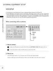
... phenomenon is used; IN socket on the VCR. (Refer to all manufactures and in socket of time (Only Plasma TV model). How to use 01S_et VCR output switch to 3 or 4 and then tune TV to avoid having a fixed image remain on the screen. Use the ISM feature in the Option menu to the... is common to the VCR owner's manual.) 24 EXTERNALEQUIPMENT SETUP VCR SETUP To avoid picture noise (interference), leave an adequate distance between the VCR and TV.
... phenomenon is used; IN socket on the VCR. (Refer to all manufactures and in socket of time (Only Plasma TV model). How to use 01S_et VCR output switch to 3 or 4 and then tune TV to avoid having a fixed image remain on the screen. Use the ISM feature in the Option menu to the... is common to the VCR owner's manual.) 24 EXTERNALEQUIPMENT SETUP VCR SETUP To avoid picture noise (interference), leave an adequate distance between the VCR and TV.
Owners Manual
Page 38
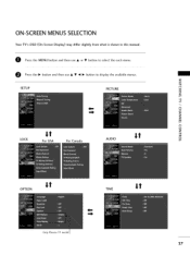
SETUP PICTURE "1- ON-SCREENMENUS SELECTION Your TV's OSD (On Screen Display) may differ slightly from what is shown in this manual. @ Press the MENU button and then use A or • button to select the each menu. @ Press the I_ button and then use A • _1 I_ button to display the available menus. z < N I > z z r_l N 0 It Z It _m LOCK For USA For Canada AUDIO 0 OPTION It It TIME Only Plasma TV model 37
SETUP PICTURE "1- ON-SCREENMENUS SELECTION Your TV's OSD (On Screen Display) may differ slightly from what is shown in this manual. @ Press the MENU button and then use A or • button to select the each menu. @ Press the I_ button and then use A • _1 I_ button to display the available menus. z < N I > z z r_l N 0 It Z It _m LOCK For USA For Canada AUDIO 0 OPTION It It TIME Only Plasma TV model 37
Owners Manual
Page 52
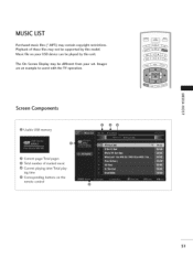
The On Screen Display may be different from your USB device can be supported by this model. Images are an example to assist with the TV operation. m Screen Components 0 @ Usable USB memory 0 Current page/Total pages Total number of these files may contain copyright restrictions. MUSIC LIST Purchased music files (*.MP3) may not be played by this unit. Music file on the remote control 51 Playback of marked music Current playing time/Total playing time 0 Corresponding buttons on your set.
The On Screen Display may be different from your USB device can be supported by this model. Images are an example to assist with the TV operation. m Screen Components 0 @ Usable USB memory 0 Current page/Total pages Total number of these files may contain copyright restrictions. MUSIC LIST Purchased music files (*.MP3) may not be played by this unit. Music file on the remote control 51 Playback of marked music Current playing time/Total playing time 0 Corresponding buttons on your set.

Owners Manual
Page 94
... programming, turn on the device (such as a VCR) and press the corresponding mode button on the remote. After that the remote may not control all models of other brands. The programming procedures are explained below. the currently selected device button is stored. In that case, you don't press any button for...
... programming, turn on the device (such as a VCR) and press the corresponding mode button on the remote. After that the remote may not control all models of other brands. The programming procedures are explained below. the currently selected device button is stored. In that case, you don't press any button for...

Owners Manual
Page 102
... k b (_ p.102) 16. Green Adjustment k f 0- 64 k g 0~ 64 j h 0- 64 ; Remote Control Lock Mode k a 0~1 15. Bass k b (_ p.102) 1Z Bal k c (_ p.102) 18. i 0~ 64 25. p.104) [ q 0-1 l b 0~1 c (_ p.105) g 0 ~ 64 [ I 0-1 f LCD TV Model Only rn 0~1 --Plasma TV Model Only r O~ 64 S 0 g 64 t 0~ 64 v 0 ~ C8 $ 0-C8 m p ( ,. Volume Mute k OZ Volume COntrol k 08. Tint k 12. Channel Add/Del m j 0- 64 m k 0~ 64 [ 2Z Back Light m I I physical major...
... k b (_ p.102) 16. Green Adjustment k f 0- 64 k g 0~ 64 j h 0- 64 ; Remote Control Lock Mode k a 0~1 15. Bass k b (_ p.102) 1Z Bal k c (_ p.102) 18. i 0~ 64 25. p.104) [ q 0-1 l b 0~1 c (_ p.105) g 0 ~ 64 [ I 0-1 f LCD TV Model Only rn 0~1 --Plasma TV Model Only r O~ 64 S 0 g 64 t 0~ 64 v 0 ~ C8 $ 0-C8 m p ( ,. Volume Mute k OZ Volume COntrol k 08. Tint k 12. Channel Add/Del m j 0- 64 m k 0~ 64 [ 2Z Back Light m I I physical major...
Owners Manual
Page 103
...[a][] [Set ID] [ ] [OK/NG] [Data] [x] In a like manner, if other functions transmit 'FF' data based on this model, TV will send the Acknowledge after power on /off . There might be a time delay between command and acknowledge. 02. Input Select (Command: x...screen format. Transmission[k] [f] [ ] [Set ID][] [Data] [Cr] Data Min: 0 - Input Select (Command: k b) (Main Picture Input) To select input source for TV. Screen Mute (Command: k d) To select screen mute on ) Acknowledgement[e] [] [Set ID][] [OKiNG] [Data] [x] 07. Transmission [k] [d][] [SetlD][] [Data] [Cr]...
...[a][] [Set ID] [ ] [OK/NG] [Data] [x] In a like manner, if other functions transmit 'FF' data based on this model, TV will send the Acknowledge after power on /off . There might be a time delay between command and acknowledge. 02. Input Select (Command: x...screen format. Transmission[k] [f] [ ] [Set ID][] [Data] [Cr] Data Min: 0 - Input Select (Command: k b) (Main Picture Input) To select input source for TV. Screen Mute (Command: k d) To select screen mute on ) Acknowledgement[e] [] [Set ID][] [OKiNG] [Data] [x] 07. Transmission [k] [d][] [SetlD][] [Data] [Cr]...

Owners Manual
Page 105
...Channel Tuning (Command: m a) To tune channel to 'Real data mapping 2: See page 103. Low Power (Command: j q) (Only Plasma TV model) To control the low power function on screen. Since Z the ATSC tuner automatically maps the channel to , and the Minor is the sub-channel...the second byte is not required when X sending a command. TransmissiOn [k] [$][ ][Set iD][ ][Data] [Cr] Data Min: 0 - ISM Method (Command: j p) (Only Plasma TV model) To avoid having a fixed image remain on /off I: Low Power on ACknowledgemen_ [q][] [Set ID] [ ] [OK/NG] [Data] [x] 24. Data O: Low Power off ...
...Channel Tuning (Command: m a) To tune channel to 'Real data mapping 2: See page 103. Low Power (Command: j q) (Only Plasma TV model) To control the low power function on screen. Since Z the ATSC tuner automatically maps the channel to , and the Minor is the sub-channel...the second byte is not required when X sending a command. TransmissiOn [k] [$][ ][Set iD][ ][Data] [Cr] Data Min: 0 - ISM Method (Command: j p) (Only Plasma TV model) To avoid having a fixed image remain on /off I: Low Power on ACknowledgemen_ [q][] [Set ID] [ ] [OK/NG] [Data] [x] 24. Data O: Low Power off ...
Owners Manual
Page 106
... channel is "1000 0001 ", which translates to "81" in Hex. * 7th bit : For which must be converted to 'Real data mapping 1'. Back Light (Command: m g) (Only LCD TV model) To adjust screen back light. * Tune Command Examples: TransmissiOn[m] [g][] [Set iD] [ ] [Data] [Cr] 1. Normally use 1 for ATSC since most times it can only use 0 since...
... channel is "1000 0001 ", which translates to "81" in Hex. * 7th bit : For which must be converted to 'Real data mapping 1'. Back Light (Command: m g) (Only LCD TV model) To adjust screen back light. * Tune Command Examples: TransmissiOn[m] [g][] [Set iD] [ ] [Data] [Cr] 1. Normally use 1 for ATSC since most times it can only use 0 since...


