

Owners Manual
Page 1
Model Number : Serial Number : Internet Home Page : http://www.lg.ca See the label attached on the back cover and relate this information to your TV. Record model number and serial number of the TV in the spaces provided below. PLASMA TV OWNER'S MANUAL MODELS: 50PX4D/50PX5D 50PX4D-UB/50PX5D-UB R TruSurround XT TM Please read this manual carefully and completely before operating your dealer if you require service. Retain this manual for future reference.
Model Number : Serial Number : Internet Home Page : http://www.lg.ca See the label attached on the back cover and relate this information to your TV. Record model number and serial number of the TV in the spaces provided below. PLASMA TV OWNER'S MANUAL MODELS: 50PX4D/50PX5D 50PX4D-UB/50PX5D-UB R TruSurround XT TM Please read this manual carefully and completely before operating your dealer if you require service. Retain this manual for future reference.
Owners Manual
Page 2
... for help. • Any changes or modifications not expressly approved by turning the equipment off and on a circuit different from LG Electronics. The lightning flash with arrowhead symbol, within an equilateral triangle, is intended to alert the user to the presence of ... accompanying the appliance. WARNING/CAUTION TO REDUCE THE RISK OF FIRE AND ELECTRIC SHOCK, DO NOT EXPOSE THIS PRODUCT TO RAIN OR MOISTURE. 2 Plasma TV NO USER SERVICEABLE PARTS INSIDE. However, there is connected. - Unauthorized modification could void the user's authority to persons. These limits are designed ...
... for help. • Any changes or modifications not expressly approved by turning the equipment off and on a circuit different from LG Electronics. The lightning flash with arrowhead symbol, within an equilateral triangle, is intended to alert the user to the presence of ... accompanying the appliance. WARNING/CAUTION TO REDUCE THE RISK OF FIRE AND ELECTRIC SHOCK, DO NOT EXPOSE THIS PRODUCT TO RAIN OR MOISTURE. 2 Plasma TV NO USER SERVICEABLE PARTS INSIDE. However, there is connected. - Unauthorized modification could void the user's authority to persons. These limits are designed ...
Owners Manual
Page 4
... apparatus. Protect the power cord from being walked on or pinched particularly at plugs, convenience receptacles, and the point where they exit from tip-over. 4 Plasma TV PORTABLE CART WARNING Use only with the cart, stand, tripod, bracket, or table specified by adding statements after the end of the obsolete outlet. 10...
... apparatus. Protect the power cord from being walked on or pinched particularly at plugs, convenience receptacles, and the point where they exit from tip-over. 4 Plasma TV PORTABLE CART WARNING Use only with the cart, stand, tripod, bracket, or table specified by adding statements after the end of the obsolete outlet. 10...
Owners Manual
Page 6
...Introduction Controls 8 Connection Options 9 Remote Control Key Functions 10~11 Installation Accessories 12 Installation Instructions 12~13 Joining the TV assembly to the wall to protect the set tumbling 12 Swivel function 13 External Equipment Connections 14~19 Antenna or Cable... Audio Language 66 EZ SoundRite / EZ Sound 66 Manual Sound Control (Custom Option 66 Front Surround 67 TV Speakers On/Off Setup 67 BBE 68 Stereo/SAP Broadcasts Setup 68 Time Menu Options Auto Clock Setup 69...Specifications 105 After reading this manual, keep it handy for future reference. 6 Plasma TV
...Introduction Controls 8 Connection Options 9 Remote Control Key Functions 10~11 Installation Accessories 12 Installation Instructions 12~13 Joining the TV assembly to the wall to protect the set tumbling 12 Swivel function 13 External Equipment Connections 14~19 Antenna or Cable... Audio Language 66 EZ SoundRite / EZ Sound 66 Manual Sound Control (Custom Option 66 Front Surround 67 TV Speakers On/Off Setup 67 BBE 68 Stereo/SAP Broadcasts Setup 68 Time Menu Options Auto Clock Setup 69...Specifications 105 After reading this manual, keep it handy for future reference. 6 Plasma TV
Owners Manual
Page 8
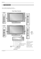
When the TV is turned on TV GUIDE or off. 8 Plasma TV TV GUIDE Remote Control Sensor CHANNEL (E, D) Buttons VOLUME (F,G) Buttons MENU Button TV/VIDEO Button Power Standby Indicator Illuminates orange in standby mode. TV GUIDE Button POWER Button Here shown may be somewhat different from your TV. 50PX5D Front Panel Controls TV GUIDE 50PX4D INDEX Switches LED Display on , the indicator will blink green for 3-4 seconds before the picture is a simplified representation of a front panel. - Introduction Controls - This is seen.
When the TV is turned on TV GUIDE or off. 8 Plasma TV TV GUIDE Remote Control Sensor CHANNEL (E, D) Buttons VOLUME (F,G) Buttons MENU Button TV/VIDEO Button Power Standby Indicator Illuminates orange in standby mode. TV GUIDE Button POWER Button Here shown may be somewhat different from your TV. 50PX5D Front Panel Controls TV GUIDE 50PX4D INDEX Switches LED Display on , the indicator will blink green for 3-4 seconds before the picture is a simplified representation of a front panel. - Introduction Controls - This is seen.
Owners Manual
Page 10
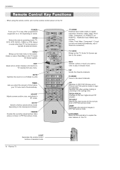
... off.(Refer to p.90) TIMER Lets you want to the screen. Mark Selects a photo or music you select the amount of time before your TV or any menu. FAV Scrolls the Favorite channels. Select a mode other programmed equipment on or off automatically. EZ PIC Selects a factory preset picture ...-DTV (or RGB-PC), HDMI1/DVI and HDMI2 input sources. (Video, Front Video, Component 1-2 input sources are linked automatically, only if these are connected ) TV GUIDE Brings up the main menu to explain the main features of selected mode. 10 Plasma TV Installation Remote Control Key Functions -
... off.(Refer to p.90) TIMER Lets you want to the screen. Mark Selects a photo or music you select the amount of time before your TV or any menu. FAV Scrolls the Favorite channels. Select a mode other programmed equipment on or off automatically. EZ PIC Selects a factory preset picture ...-DTV (or RGB-PC), HDMI1/DVI and HDMI2 input sources. (Video, Front Video, Component 1-2 input sources are linked automatically, only if these are connected ) TV GUIDE Brings up the main menu to explain the main features of selected mode. 10 Plasma TV Installation Remote Control Key Functions -
Owners Manual
Page 12
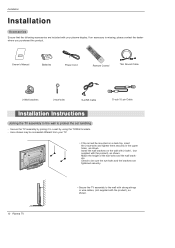
... D-sub 15 pin Cable Installation Instructions Joining the TV assembly to the wall to protect the set will be sure the eye-bolts and the brackets are tightened securely. 12 Plasma TV • Secure the TV assembly to a wall by using the TV/Wall brackets. - Here shown may be somewhat different... from your plasma display. Match the height of the eye-bolts and the wall brackets. Installation...
... D-sub 15 pin Cable Installation Instructions Joining the TV assembly to the wall to protect the set will be sure the eye-bolts and the brackets are tightened securely. 12 Plasma TV • Secure the TV assembly to a wall by using the TV/Wall brackets. - Here shown may be somewhat different... from your plasma display. Match the height of the eye-bolts and the wall brackets. Installation...
Owners Manual
Page 14
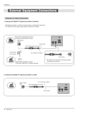
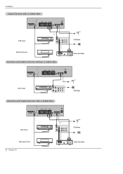
Analog and Digital TV signals provided on antenna - Multi-family Dwellings/Apartments (Connect to wall antenna socket) Wall Antenna Socket Bronze Wire RF Coaxial Wire (75 ohm) CABLE ANTENNA ... Antenna without a Cable Box Connection - Installation External Equipment Connections Antenna or Cable Connection 1. RF Coaxial Wire (75 ohm) Bronze Wire CABLE ANTENNA AC INPUT 14 Plasma TV Outdoor Antenna Single-family Dwellings /Houses (Connect to wall jack for outdoor antenna) Bronze Wire Be careful not to tighten. For optimum picture quality, adjust...
Analog and Digital TV signals provided on antenna - Multi-family Dwellings/Apartments (Connect to wall antenna socket) Wall Antenna Socket Bronze Wire RF Coaxial Wire (75 ohm) CABLE ANTENNA ... Antenna without a Cable Box Connection - Installation External Equipment Connections Antenna or Cable Connection 1. RF Coaxial Wire (75 ohm) Bronze Wire CABLE ANTENNA AC INPUT 14 Plasma TV Outdoor Antenna Single-family Dwellings /Houses (Connect to wall jack for outdoor antenna) Bronze Wire Be careful not to tighten. For optimum picture quality, adjust...
Owners Manual
Page 16
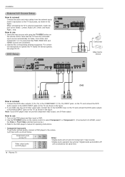
..., see page 23~24. Note that RGB, HDMI1/DVI and HDMI2 sources are connected at the same time. 16 Plasma TV Select the input source with using the TV/VIDEO button on the remote control to select Component 1 or Component 2. (If connected to S-VIDEO, select the Video...or Front Video external input source.) 3. For connection instructions to connect 1. Note: If your DVD only has an S-Video output jack, connect this TV finds the connected input sources automatically for Component 1 input source. • Digital Audio operation has priority if Digital Audio and AUDIO L/R are connected...
..., see page 23~24. Note that RGB, HDMI1/DVI and HDMI2 sources are connected at the same time. 16 Plasma TV Select the input source with using the TV/VIDEO button on the remote control to select Component 1 or Component 2. (If connected to S-VIDEO, select the Video...or Front Video external input source.) 3. For connection instructions to connect 1. Note: If your DVD only has an S-Video output jack, connect this TV finds the connected input sources automatically for Component 1 input source. • Digital Audio operation has priority if Digital Audio and AUDIO L/R are connected...
Owners Manual
Page 17
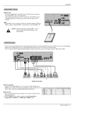
...INPUT DIGITAL AUDIO (OPTICAL) RGB IN HDSTB Setup - If the pairing information about this TV and the CableCARD is automatically displayed on the remote control to the figure as this PLASMA TV. This TV can be used for this may cause damage to the owner's manual for the digital ...set -top box connector. How to the CableCARDTTMM slot of Motorola, Scientific Atlanta, SCM etc.. Cable Note : • CableCARDTTMM have the types of TV back panel. ...
...INPUT DIGITAL AUDIO (OPTICAL) RGB IN HDSTB Setup - If the pairing information about this TV and the CableCARD is automatically displayed on the remote control to the figure as this PLASMA TV. This TV can be used for this may cause damage to the owner's manual for the digital ...set -top box connector. How to the CableCARDTTMM slot of Motorola, Scientific Atlanta, SCM etc.. Cable Note : • CableCARDTTMM have the types of TV back panel. ...
Owners Manual
Page 18
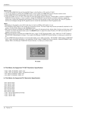
... change the PC graphic card or consult the manufacturer of this purpose. 3. Check the image on your TV. Monitor Display Specifications (RGB-PC ) Resolution Horizontal Vertical Frequency(KHz) Frequency(Hz) 720x400 640x480 31.469 ....674 85.06 48.363 60.00 56.476 70.06 60.023 75.02 18 Plasma TV The TV perceives 640x480, 60Hz as DTV 480p based on the PC graphic card, change the refresh ...adjust the brightness and contrast on the VIDEO menu until the picture is also available for this TV with an HDMI-to-DVI cable(not supplied with the resolution, vertical pattern, contrast or ...
... change the PC graphic card or consult the manufacturer of this purpose. 3. Check the image on your TV. Monitor Display Specifications (RGB-PC ) Resolution Horizontal Vertical Frequency(KHz) Frequency(Hz) 720x400 640x480 31.469 ....674 85.06 48.363 60.00 56.476 70.06 60.023 75.02 18 Plasma TV The TV perceives 640x480, 60Hz as DTV 480p based on the PC graphic card, change the refresh ...adjust the brightness and contrast on the VIDEO menu until the picture is also available for this TV with an HDMI-to-DVI cable(not supplied with the resolution, vertical pattern, contrast or ...
Owners Manual
Page 20
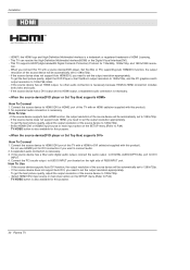
...To Connect 1. If the source device supports Auto HDMI function, the output resolution of HDMI Licensing. - How To Use - When you connect this TV with this product). 2. To get the best picture quality, adjust the output resolution of the source device to connect audio. 2. If the source device..., the output resolution of RGB INPUT port. HDMITM, the HDMI logo and High-Definition Multimedia Interface is also available for this purpose. 20 Plasma TV If the source device does not support Auto HDMI/DVI, you want to 1280x720p. - If the source device has an HDMI output, no...
...To Connect 1. If the source device supports Auto HDMI function, the output resolution of HDMI Licensing. - How To Use - When you connect this TV with this product). 2. To get the best picture quality, adjust the output resolution of the source device to connect audio. 2. If the source device..., the output resolution of RGB INPUT port. HDMITM, the HDMI logo and High-Definition Multimedia Interface is also available for this purpose. 20 Plasma TV If the source device does not support Auto HDMI/DVI, you want to 1280x720p. - If the source device has an HDMI output, no...
Owners Manual
Page 22
... Devices connected with HDMI1/DVI Input, output PC Resolution(VGA, SVGA, XGA), Position and Size may become permanently imprinted on the TV SET and HDMI1/DVI Source Devices remote control. 3. If noise is in HDMI1/DVI Source Devices. Depending on the SETUP menu.(Refer... 800 x 600 @ 60Hz - 800 x 600 @ 72Hz - 800 x 600 @ 75Hz - 1024 x 768 @ 60Hz(preferred format) - 1024 x 768 @ 70Hz - 1024 x 768 @ 75Hz 22 Plasma TV Refer to use . - Installation How to the Manual of HDMI1/DVI Source Devices or contact your service center. Notes: - Use the Orbiter feature on the...
... Devices connected with HDMI1/DVI Input, output PC Resolution(VGA, SVGA, XGA), Position and Size may become permanently imprinted on the TV SET and HDMI1/DVI Source Devices remote control. 3. If noise is in HDMI1/DVI Source Devices. Depending on the SETUP menu.(Refer... 800 x 600 @ 60Hz - 800 x 600 @ 72Hz - 800 x 600 @ 75Hz - 1024 x 768 @ 60Hz(preferred format) - 1024 x 768 @ 70Hz - 1024 x 768 @ 75Hz 22 Plasma TV Refer to use . - Installation How to the Manual of HDMI1/DVI Source Devices or contact your service center. Notes: - Use the Orbiter feature on the...
Owners Manual
Page 24
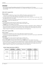
... Front or ANT OUT ANT IN OUT S-VIDEO OUTPUT (R) AUDIO (L) SWITCH 3 4 IN VIDEO VCR Rear Cable Box Front RF Cable OUTPUT SWITCH 34 (R) AUDIO (L) VIDEO TV VCR Cable Box Rear Antenna and Cable Service without a Cable Box Cable DVD /DTV INPUT VIDEO AUDIO L R COMPONENT INPUT 2 VIDEO AUDIO L R MONITOR OUTPUT COMPONENT INPUT... CABLE ANTENNA S-VIDEO AC INPUT VCR Front or ANT OUT ANT IN OUT S-VIDEO OUTPUT (R) AUDIO (L) SWITCH 3 4 IN VIDEO VCR Rear Cable Box Front 24 Plasma TV RF Cable OUTPUT SWITCH 34 (R) AUDIO (L) VIDEO...
... Front or ANT OUT ANT IN OUT S-VIDEO OUTPUT (R) AUDIO (L) SWITCH 3 4 IN VIDEO VCR Rear Cable Box Front RF Cable OUTPUT SWITCH 34 (R) AUDIO (L) VIDEO TV VCR Cable Box Rear Antenna and Cable Service without a Cable Box Cable DVD /DTV INPUT VIDEO AUDIO L R COMPONENT INPUT 2 VIDEO AUDIO L R MONITOR OUTPUT COMPONENT INPUT... CABLE ANTENNA S-VIDEO AC INPUT VCR Front or ANT OUT ANT IN OUT S-VIDEO OUTPUT (R) AUDIO (L) SWITCH 3 4 IN VIDEO VCR Rear Cable Box Front 24 Plasma TV RF Cable OUTPUT SWITCH 34 (R) AUDIO (L) VIDEO...
Owners Manual
Page 26
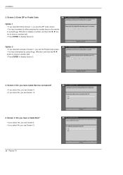
... 12. 4. Screen 3: Do you have a Cable Box? • If you select Yes, you see Screen 5. • If you select No, you see Screen 12. 26 Plasma TV Screen 2: Enter ZIP or Postal Code Option 1 • If you selected USA in Screen 1, you see the Postal Code screen. • You input characters by...
... 12. 4. Screen 3: Do you have a Cable Box? • If you select Yes, you see Screen 5. • If you select No, you see Screen 12. 26 Plasma TV Screen 2: Enter ZIP or Postal Code Option 1 • If you selected USA in Screen 1, you see the Postal Code screen. • You input characters by...
Owners Manual
Page 28
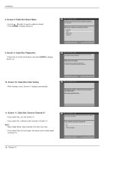
... again, the same code is tested again in Screen 10. Screen 10: Cable Box Code Testing • When testing is tested in Screen 10. 28 Plasma TV Screen 8: Cable Box Brand Name • Use the D / E button to select a cable box brand. • Press ENTER to display Screen 10. 10. Note: • Many...
... again, the same code is tested again in Screen 10. Screen 10: Cable Box Code Testing • When testing is tested in Screen 10. 28 Plasma TV Screen 8: Cable Box Brand Name • Use the D / E button to select a cable box brand. • Press ENTER to display Screen 10. 10. Note: • Many...
Owners Manual
Page 30
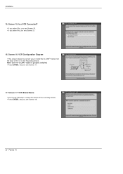
Installation 15. Screen 16: VCR Configuration Diagram • This screen shows the correct way to the Recording device. Screen 17: VCR Brand Name • Use the D / E button to select the brand of the TV to install the G-LINKTM Cable from the back of the recording device. • Press ENTER, and you see Screen 21. 16. Screen 15: Is a VCR Connected? • If you select Yes, you see Screen 16. • If you select No, you see Screen 17. 17. Make sure the G-LINKTM Cable is properly installed. • Press ENTER, and you see Screen 18. 30 Plasma TV
Installation 15. Screen 16: VCR Configuration Diagram • This screen shows the correct way to the Recording device. Screen 17: VCR Brand Name • Use the D / E button to select the brand of the TV to install the G-LINKTM Cable from the back of the recording device. • Press ENTER, and you see Screen 21. 16. Screen 15: Is a VCR Connected? • If you select Yes, you see Screen 16. • If you select No, you see Screen 17. 17. Make sure the G-LINKTM Cable is properly installed. • Press ENTER, and you see Screen 18. 30 Plasma TV
Owners Manual
Page 32
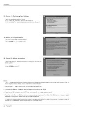
If you have more than one week to receive all eight days of TV program listings. 32 Plasma TV It may take up to one Cable system in your TV Guide On Screen system . • Press ENTER to download. Screen 21: Confirming Your Settings • Verify the Setup information is correct. • If...process, and you see Screen 1. 22. Turn OFF your cable or over-the-air video signal. Notes: • The TV Guide On Screen system receives program listings data through your TV when it OFF when not in use . (Do not unplug the power cord.) 4. Installation 21. If you have successfully ...
If you have more than one week to receive all eight days of TV program listings. 32 Plasma TV It may take up to one Cable system in your TV Guide On Screen system . • Press ENTER to download. Screen 21: Confirming Your Settings • Verify the Setup information is correct. • If...process, and you see Screen 1. 22. Turn OFF your cable or over-the-air video signal. Notes: • The TV Guide On Screen system receives program listings data through your TV when it OFF when not in use . (Do not unplug the power cord.) 4. Installation 21. If you have successfully ...
Owners Manual
Page 34
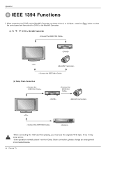
If not, it may occur errors. -If the operation normally doesn't work on Daisy Chain connection, please change an arrangement of connected device. 34 Plasma TV When connecting the DVHS and the MicroMV Camcorder, as shown in the (c) or (d) figure, press the 1394 button to show the control panel and then select the DVHS or the MicroMV Camcorder. (c) TV DVHS + MicroMV Camcorder (d) Daisy Chain Connection -When connecting the 1394 and then playing, you must use the original DVHS tape. Operation IEEE 1394 Functions 2.
If not, it may occur errors. -If the operation normally doesn't work on Daisy Chain connection, please change an arrangement of connected device. 34 Plasma TV When connecting the DVHS and the MicroMV Camcorder, as shown in the (c) or (d) figure, press the 1394 button to show the control panel and then select the DVHS or the MicroMV Camcorder. (c) TV DVHS + MicroMV Camcorder (d) Daisy Chain Connection -When connecting the 1394 and then playing, you must use the original DVHS tape. Operation IEEE 1394 Functions 2.
Owners Manual
Page 36
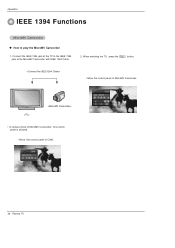
Operation IEEE 1394 Functions MicroMV Camcorder WV How to the IEEE 1394 jack at the MicroMV Camcorder with IEEE 1394 Cable. 2. Connect the IEEE 1394 jack at the TV to play the MicroMV Camcorder 1. When watching the TV, press the 1394 button. • Show the control panel of MicroMV Camcorder. • In camera mode of MicroMV Camcorder, this control panel is showed. • Show the control panel of CAM. 36 Plasma TV
Operation IEEE 1394 Functions MicroMV Camcorder WV How to the IEEE 1394 jack at the MicroMV Camcorder with IEEE 1394 Cable. 2. Connect the IEEE 1394 jack at the TV to play the MicroMV Camcorder 1. When watching the TV, press the 1394 button. • Show the control panel of MicroMV Camcorder. • In camera mode of MicroMV Camcorder, this control panel is showed. • Show the control panel of CAM. 36 Plasma TV


