Owners Manual
Page 2
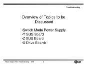
Troubleshooting Overview of Topics to be Discussed •Switch Mode Power Supply •Y SUS Board •Z SUS Board •X Drive Boards Plasma Display Panel Troubleshooting - 2007 2
Troubleshooting Overview of Topics to be Discussed •Switch Mode Power Supply •Y SUS Board •Z SUS Board •X Drive Boards Plasma Display Panel Troubleshooting - 2007 2

Owners Manual
Page 6
... the VA, VS, and 5v DC, set will output 19v,12v, 6v, 5vS, and 3.3v Supplies. • Full Power On - Power Sequence • AC Cord Plugged in and turned off for TVGOS Data. • Standby Operation - Plasma Display Panel Troubleshooting - 2007 6 The unit can be taken out of Deep Sleep Mode. Guide Plus... P800 Pin 6 and used to turn on the VA, and VS Supplies • 5V-M Sent from the Digital Board to the Power Board to turn on 5V-DC. • 5V-D is sent from the Power Board Pin1 of P800 to bring the Power Supply out of DS Mode as needed for approximately 2 hours and go into Deep...
... the VA, VS, and 5v DC, set will output 19v,12v, 6v, 5vS, and 3.3v Supplies. • Full Power On - Power Sequence • AC Cord Plugged in and turned off for TVGOS Data. • Standby Operation - Plasma Display Panel Troubleshooting - 2007 6 The unit can be taken out of Deep Sleep Mode. Guide Plus... P800 Pin 6 and used to turn on the VA, and VS Supplies • 5V-M Sent from the Digital Board to the Power Board to turn on 5V-DC. • 5V-D is sent from the Power Board Pin1 of P800 to bring the Power Supply out of DS Mode as needed for approximately 2 hours and go into Deep...
Owners Manual
Page 7
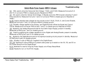
... switch on the VA, VS, and 5V on the 5V-DC Supply. Adjusted at P800 pin 5 present after power up to develop Y and Z Drive waveforms. Measured from the Digital Board. • 5v-D Switched 5v used for the Audio Output Supply, present in standby. Plasma Display Panel Troubleshooting - 2007 7 Measured from pins 1 and 2 of connector P805...
... switch on the VA, VS, and 5V on the 5V-DC Supply. Adjusted at P800 pin 5 present after power up to develop Y and Z Drive waveforms. Measured from the Digital Board. • 5v-D Switched 5v used for the Audio Output Supply, present in standby. Plasma Display Panel Troubleshooting - 2007 7 Measured from pins 1 and 2 of connector P805...
Owners Manual
Page 22
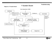
Bottom Left X Board FETs amplify Sustain Waveform Troubleshooting Control Board Logic signals needed to generate drive waveform Transfer Waveform to Y Drive Board Display Panel Plasma Display Panel Troubleshooting - 2007 22 SMPS Receive 5V,Va, Vs from SMPS Distributes 5v IPM generates Sustain Waveform Generates Vsc, -Vy from 5v VA Vs by transformer. Diagram of Y Sustain Board Y Sustain Board Z SUS Board Distributes 5v VA VS Distributes 5v VA Power Supply Board -
Bottom Left X Board FETs amplify Sustain Waveform Troubleshooting Control Board Logic signals needed to generate drive waveform Transfer Waveform to Y Drive Board Display Panel Plasma Display Panel Troubleshooting - 2007 22 SMPS Receive 5V,Va, Vs from SMPS Distributes 5v IPM generates Sustain Waveform Generates Vsc, -Vy from 5v VA Vs by transformer. Diagram of Y Sustain Board Y Sustain Board Z SUS Board Distributes 5v VA VS Distributes 5v VA Power Supply Board -


