
Owners Manual
Page 4
... to locate voltage and test points needed for the Single Scan Plasma. V SET_UP -VY VSC Z_BIAS Plasma Display Panel Troubleshooting - 2007 4 Switch Mode Power Supply Troubleshooting This Section of the PDP for the correct voltage levels for the DC 5v, VA, VS, V SET UP, -VY, VSC, and Z Bias as they will cover troubleshooting the Switch Mode Power Supply for troubleshooting and alignments. • DC Voltages developed on the SMPS • Adjustments VA...
... to locate voltage and test points needed for the Single Scan Plasma. V SET_UP -VY VSC Z_BIAS Plasma Display Panel Troubleshooting - 2007 4 Switch Mode Power Supply Troubleshooting This Section of the PDP for the correct voltage levels for the DC 5v, VA, VS, V SET UP, -VY, VSC, and Z Bias as they will cover troubleshooting the Switch Mode Power Supply for troubleshooting and alignments. • DC Voltages developed on the SMPS • Adjustments VA...
Owners Manual
Page 5
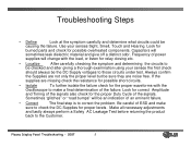
.... Plasma Display Panel Troubleshooting - 2007 5 Look for burned parts and check for the proper Duty Cycle of the signals. Sometimes "glitches" or "road bumps" will be an indication of power supplies will sometimes leak dielectric material and give off a distinct odor. Use your senses the first check should always be causing the failure. If the supplies are noise free. Always confirm the Supplies...
.... Plasma Display Panel Troubleshooting - 2007 5 Look for burned parts and check for the proper Duty Cycle of the signals. Sometimes "glitches" or "road bumps" will be an indication of power supplies will sometimes leak dielectric material and give off a distinct odor. Use your senses the first check should always be causing the failure. If the supplies are noise free. Always confirm the Supplies...

Owners Manual
Page 6
... the Digital Board to the Power Board to turn on the VA, and VS Supplies • 5V-M Sent from the Power Board Pin1 of P800 to turn on connector P800 Pin 5 used to bring the Power Supply out of DS Mode as needed for approximately 2 hours and go into Deep Sleep Mode. SMPS Operating Modes Troubleshooting • Deep Sleep Mode - Plasma Display Panel Troubleshooting - 2007 6 Guide Plus not programmed or Cable Card not installed and set will output 19v...
... the Digital Board to the Power Board to turn on the VA, and VS Supplies • 5V-M Sent from the Power Board Pin1 of P800 to turn on connector P800 Pin 5 used to bring the Power Supply out of DS Mode as needed for approximately 2 hours and go into Deep Sleep Mode. SMPS Operating Modes Troubleshooting • Deep Sleep Mode - Plasma Display Panel Troubleshooting - 2007 6 Guide Plus not programmed or Cable Card not installed and set will output 19v...
Owners Manual
Page 7
... to Bias the Signal and Control circuits. Standby voltage applied to the Analog, and Digital Boards to chassis ground. Adjusted at P803 pins 9 and 10 to chassis ground. • 6v Applied to the Digital Board used for the Audio Output Supply, present in standby. to drive the...Used for the circuits on the 5V-DC Supply. Adjusted at P802 pins 1 and 2 to the Digital Board. • VS- Measured at VR951 • VA 60v used to bring the Power Supply out of connector P804 to drive the Vertical Grid Voltage, X Boards and in standby. Plasma Display Panel Troubleshooting...
... to Bias the Signal and Control circuits. Standby voltage applied to the Analog, and Digital Boards to chassis ground. Adjusted at P803 pins 9 and 10 to chassis ground. • 6v Applied to the Digital Board used for the Audio Output Supply, present in standby. to drive the...Used for the circuits on the 5V-DC Supply. Adjusted at P802 pins 1 and 2 to the Digital Board. • VS- Measured at VR951 • VA 60v used to bring the Power Supply out of connector P804 to drive the Vertical Grid Voltage, X Boards and in standby. Plasma Display Panel Troubleshooting...
Owners Manual
Page 14
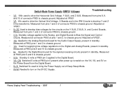
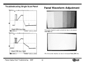
Troubleshooting Single Scan Panel *Waveforms may vary with the probe set to here. Ground VSET DN +VSC Plasma Display Panel Troubleshooting - 2007 14 Readings are taken with different Y_SUSTAIN PCB part #'s. Normal Waveform RAMP UP Panel Waveform Adjustment 35 micro seconds Scope TP 000 -VY 180 micro seconds VSET UP This test point is the reference for all the following signals referred to 10x1.
Troubleshooting Single Scan Panel *Waveforms may vary with the probe set to here. Ground VSET DN +VSC Plasma Display Panel Troubleshooting - 2007 14 Readings are taken with different Y_SUSTAIN PCB part #'s. Normal Waveform RAMP UP Panel Waveform Adjustment 35 micro seconds Scope TP 000 -VY 180 micro seconds VSET UP This test point is the reference for all the following signals referred to 10x1.
Owners Manual
Page 16
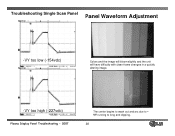
Troubleshooting Single Scan Panel Panel Waveform Adjustment Vset DN too low The center begins to wash out and arc due to increased Vset_DN time. 16 Vset DN too high Plasma Display Panel Troubleshooting - 2007 All of the center washes out due to decreased Vset DN time.
Troubleshooting Single Scan Panel Panel Waveform Adjustment Vset DN too low The center begins to wash out and arc due to increased Vset_DN time. 16 Vset DN too high Plasma Display Panel Troubleshooting - 2007 All of the center washes out due to decreased Vset DN time.
Owners Manual
Page 18
VY running to - Troubleshooting Single Scan Panel Panel Waveform Adjustment -VY too low (-154vdc) Colors and the image will bloom slightly and the unit will have difficulty with clean frame changes in a quickly altering image. -VY too high (-227vdc) Plasma Display Panel Troubleshooting - 2007 The center begins to wash out and arc due to long and clipping. 18
VY running to - Troubleshooting Single Scan Panel Panel Waveform Adjustment -VY too low (-154vdc) Colors and the image will bloom slightly and the unit will have difficulty with clean frame changes in a quickly altering image. -VY too high (-227vdc) Plasma Display Panel Troubleshooting - 2007 The center begins to wash out and arc due to long and clipping. 18

Owners Manual
Page 19
VSC too high (140 Volts) Plasma Display Panel Troubleshooting - 2007 The image will show very little change but there will Be some distortion in a quickly changing image. 19 Troubleshooting Single Scan Panel Panel Waveform Adjustment VSC too low (77 Volts) The image will show very little change but there will Be some distortion in a quickly changing image.
VSC too high (140 Volts) Plasma Display Panel Troubleshooting - 2007 The image will show very little change but there will Be some distortion in a quickly changing image. 19 Troubleshooting Single Scan Panel Panel Waveform Adjustment VSC too low (77 Volts) The image will show very little change but there will Be some distortion in a quickly changing image.
Owners Manual
Page 21
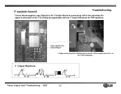
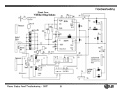
Y sustain board Troubleshooting Control Board supplies Logic Signals to the Y Sustain Board for processing, which then develops the signal to the Y Driver Boards > 110V 200V 110V 200V 80V Y Output Waveform V Y s Plasma Display Panel Troubleshooting - 2007 21 Logic signals from Control Board < Probe connect point to Oscilloscope to check Y Drive output wave form to drive both of the Y Drive Boards sequentially with the Y Output Waveform for PDP operation.
Y sustain board Troubleshooting Control Board supplies Logic Signals to the Y Sustain Board for processing, which then develops the signal to the Y Driver Boards > 110V 200V 110V 200V 80V Y Output Waveform V Y s Plasma Display Panel Troubleshooting - 2007 21 Logic signals from Control Board < Probe connect point to Oscilloscope to check Y Drive output wave form to drive both of the Y Drive Boards sequentially with the Y Output Waveform for PDP operation.
Owners Manual
Page 22
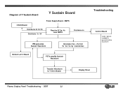
Bottom Left X Board FETs amplify Sustain Waveform Troubleshooting Control Board Logic signals needed to generate drive waveform Transfer Waveform to Y Drive Board Display Panel Plasma Display Panel Troubleshooting - 2007 22 SMPS Receive 5V,Va, Vs from SMPS Distributes 5v IPM generates Sustain Waveform Generates Vsc, -Vy from 5v VA Vs by transformer. Diagram of Y Sustain Board Y Sustain Board Z SUS Board Distributes 5v VA VS Distributes 5v VA Power Supply Board -
Bottom Left X Board FETs amplify Sustain Waveform Troubleshooting Control Board Logic signals needed to generate drive waveform Transfer Waveform to Y Drive Board Display Panel Plasma Display Panel Troubleshooting - 2007 22 SMPS Receive 5V,Va, Vs from SMPS Distributes 5v IPM generates Sustain Waveform Generates Vsc, -Vy from 5v VA Vs by transformer. Diagram of Y Sustain Board Y Sustain Board Z SUS Board Distributes 5v VA VS Distributes 5v VA Power Supply Board -
Owners Manual
Page 28
Single Scan Y Drive Output Waveform Troubleshooting Plasma Display Panel Troubleshooting - 2007 28
Single Scan Y Drive Output Waveform Troubleshooting Plasma Display Panel Troubleshooting - 2007 28
Owners Manual
Page 38
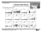
PIN1 PIN2 PIN3 Pin 1 PIN4 PIN5 PIN6 PIN7 PIN8 PIN9 PIN10 PIN11 PIN12 Plasma Display Panel Troubleshooting - 2007 38 Troubleshooting Z Board SUS Board Waveform inputs from the Control Board NOTE: These voltages will vary due to changes in design and variations in the PDP panel.
PIN1 PIN2 PIN3 Pin 1 PIN4 PIN5 PIN6 PIN7 PIN8 PIN9 PIN10 PIN11 PIN12 Plasma Display Panel Troubleshooting - 2007 38 Troubleshooting Z Board SUS Board Waveform inputs from the Control Board NOTE: These voltages will vary due to changes in design and variations in the PDP panel.
Owners Manual
Page 45
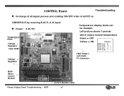
CONTROL Board Troubleshooting ◆. In charge of all signal process and creating ON/OFF order of all FET on DRIVER B/D by receiving 8 bit R, G, B input. ◆. Power : 3.3V/5V Temperature diode Voltage Regulator Flash ROM Voltage Regulator Temperature display diode can be checked. Left picture shows 7 periods which means normal temperature Green = OFF Yellow = ON Weight D15 - 8 D16 - 4 D17 - 2 D18 - 1 TEST Pattern AUTOGEN P1 Connector MCM (Micro Control Module) Plasma Display Panel Troubleshooting - 2007 LG Part Number Label 45
CONTROL Board Troubleshooting ◆. In charge of all signal process and creating ON/OFF order of all FET on DRIVER B/D by receiving 8 bit R, G, B input. ◆. Power : 3.3V/5V Temperature diode Voltage Regulator Flash ROM Voltage Regulator Temperature display diode can be checked. Left picture shows 7 periods which means normal temperature Green = OFF Yellow = ON Weight D15 - 8 D16 - 4 D17 - 2 D18 - 1 TEST Pattern AUTOGEN P1 Connector MCM (Micro Control Module) Plasma Display Panel Troubleshooting - 2007 LG Part Number Label 45

Owners Manual
Page 47
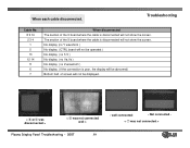
... are not present, Control board is defective LVDS Connector Replace Control Board Reconnect LVDS or Replace Control Board Plasma Display Panel Troubleshooting - 2007 47 < Display Lines > < Partly no display < Connector > Reseat Control Board Connectors Oscilator LVDS poor connection No picture < Oscillator > Remove LVDS Cable and short pins 1 and 2 of defect Part Solution Troubleshooting Defect display CONTROL IC Regular vertical lines < MCM > Replace Control Board Connector No display or Partly no display > < Poor connection > Control Board ▶ Main Defect...
... are not present, Control board is defective LVDS Connector Replace Control Board Reconnect LVDS or Replace Control Board Plasma Display Panel Troubleshooting - 2007 47 < Display Lines > < Partly no display < Connector > Reseat Control Board Connectors Oscilator LVDS poor connection No picture < Oscillator > Remove LVDS Cable and short pins 1 and 2 of defect Part Solution Troubleshooting Defect display CONTROL IC Regular vertical lines < MCM > Replace Control Board Connector No display or Partly no display > < Poor connection > Control Board ▶ Main Defect...
Owners Manual
Page 59
... not connected well > Plasma Display Panel Troubleshooting - 2007 59 - Troubleshooting Cable No. 8 9 10 2 3 4 1 5 13 12 14 11 6 7 When disconnected The section of screen will not be displayed. < ⑧ or② was disconnected > < ⑥ was not connected > The section of the X board where the cable is poor, the display will be operated ) No display ( no 5 V ) No display ( no Va,Vs ) No display ( no Y waveform ) No display ( CTRL board will...
... not connected well > Plasma Display Panel Troubleshooting - 2007 59 - Troubleshooting Cable No. 8 9 10 2 3 4 1 5 13 12 14 11 6 7 When disconnected The section of screen will not be displayed. < ⑧ or② was disconnected > < ⑥ was not connected > The section of the X board where the cable is poor, the display will be operated ) No display ( no 5 V ) No display ( no Va,Vs ) No display ( no Y waveform ) No display ( CTRL board will...
Owners Manual
Page 81
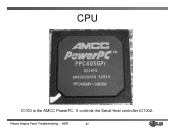
It controls the Serial Host controller IC1002. Plasma Display Panel Troubleshooting - 2007 81 CPU IC100 is the AMCC PowerPC.
It controls the Serial Host controller IC1002. Plasma Display Panel Troubleshooting - 2007 81 CPU IC100 is the AMCC PowerPC.

Owners Manual
Page 86
... List - Plasma Display Panel Troubleshooting - 2007 86 X Studio Pro is on DR and DRA series Plasma and LCD • When you press X Studio, it displays the home menu with whatever was highlighted last. • In home menu the HDD free space is displayed at the top. Manual Rec - Music List - IEEE 1394 - TV Setup • When you select TV menu or TV Setup the traditional TV Menu is displayed. • In home menu, use ▲/▼ button...
... List - Plasma Display Panel Troubleshooting - 2007 86 X Studio Pro is on DR and DRA series Plasma and LCD • When you press X Studio, it displays the home menu with whatever was highlighted last. • In home menu the HDD free space is displayed at the top. Manual Rec - Music List - IEEE 1394 - TV Setup • When you select TV menu or TV Setup the traditional TV Menu is displayed. • In home menu, use ▲/▼ button...
Owners Manual
Page 90
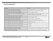
... time must be set current time. Auto Demo can start recording HDD recording space is copy protected Device problem. Current time must be stopped before timer recording starts Plasma Display Panel Troubleshooting - 2007 90 Please set before timer recording. Timer recording cannot start . Cannot display Music List when timer recording starts. Hardware error occurred. No recording space. Bad sector or bad connection or other Signal strength is too weak to bad signal. Timer...
... time must be set current time. Auto Demo can start recording HDD recording space is copy protected Device problem. Current time must be stopped before timer recording starts Plasma Display Panel Troubleshooting - 2007 90 Please set before timer recording. Timer recording cannot start . Cannot display Music List when timer recording starts. Hardware error occurred. No recording space. Bad sector or bad connection or other Signal strength is too weak to bad signal. Timer...
Owners Manual
Page 93
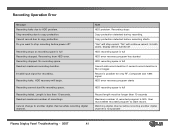
...failed. Cannot change to HDD problem. "No" will begin. User must be turned off ? Reached maximum recording duration. Invalid input signal for only RF, Composite and 1394 signal HDD error recovery program starts HDD ...error. Recording stopped. Copy protection detected before power off HDD recording space is full HDD error recovery program has started HDD recording space is full Cannot add record duration if current record duration is not possible Plasma Display Panel Troubleshooting - 2007 93 Recording Operation Error Message Recording halts due to another digital channel...
...failed. Cannot change to HDD problem. "No" will begin. User must be turned off ? Reached maximum recording duration. Invalid input signal for only RF, Composite and 1394 signal HDD error recovery program starts HDD ...error. Recording stopped. Copy protection detected before power off HDD recording space is full HDD error recovery program has started HDD recording space is full Cannot add record duration if current record duration is not possible Plasma Display Panel Troubleshooting - 2007 93 Recording Operation Error Message Recording halts due to another digital channel...
Owners Manual
Page 95
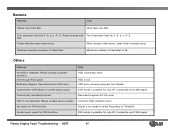
.... DVR mode is 16. Rename Message Note Please input new title. Folder with the same name exist. same folder already exists Reached maximum number of character is possible for DVR function. Maximum number of characters. Others Message Note No HDD is detected. Buffering stopped. Please contact service center. No signal for only RF, Composite and 1394 signal Plasma Display Panel Troubleshooting...
.... DVR mode is 16. Rename Message Note Please input new title. Folder with the same name exist. same folder already exists Reached maximum number of character is possible for DVR function. Maximum number of characters. Others Message Note No HDD is detected. Buffering stopped. Please contact service center. No signal for only RF, Composite and 1394 signal Plasma Display Panel Troubleshooting...


