
Specification (English)
Page 1
LCD TV 37LH20 37" High Definition LCD TV (37.0" diagonal) The LH20 Series is a feature rich HDTV available in a size for every room. TV • 720p HD Resolution • 30,000:1 Dynamic Contrast Ratio • 5ms Response Time (GTG) • 450 cd/m2 Brightness • Wide Color Gamut • ...
LCD TV 37LH20 37" High Definition LCD TV (37.0" diagonal) The LH20 Series is a feature rich HDTV available in a size for every room. TV • 720p HD Resolution • 30,000:1 Dynamic Contrast Ratio • 5ms Response Time (GTG) • 450 cd/m2 Brightness • Wide Color Gamut • ...

Specification (English)
Page 2
...Quick Setup Guide • e-Manual • Parental Control w/V-Chip • Key Lock • Closed Caption • LG SIMPLINK (HDMI CEC) • CONVENIENCE FEATURES Language English/Spanish/French/Korean Auto Tuning/Programming • Channel Add/Delete ...• Mechanical Power Off • 1080p Source Input - All rights reserved. LCD TV 37LH20 37" High Definition LCD TV (37.0" diagonal) LGusa.com LCD SPECIFICATION Screen Size (Class) 37" Class (37.0" diagonal) Native Display Resolution 1366 x 768p Brightness (cd/m2) 450 Dynamic ...
...Quick Setup Guide • e-Manual • Parental Control w/V-Chip • Key Lock • Closed Caption • LG SIMPLINK (HDMI CEC) • CONVENIENCE FEATURES Language English/Spanish/French/Korean Auto Tuning/Programming • Channel Add/Delete ...• Mechanical Power Off • 1080p Source Input - All rights reserved. LCD TV 37LH20 37" High Definition LCD TV (37.0" diagonal) LGusa.com LCD SPECIFICATION Screen Size (Class) 37" Class (37.0" diagonal) Native Display Resolution 1366 x 768p Brightness (cd/m2) 450 Dynamic ...
Owner's Manual (English)
Page 6
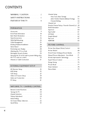
... a Desk 29 Kensington Security System 29 Securing the TV to the wall to prevent falling when the TV is used on a stand 30 Antenna or Cable Connection 31 EXTERNAL EQUIPMENT SETUP HD Receiver Setup 32 DVD Setup 35 VCR Setup 37 Other A/V Source Setup 39 Audio out Connection 40 ...PC Setup 41 WATCHING TV / CHANNEL CONTROL Remote Control Functions 48 Turning On TV 50 Channel Selection 50 Volume Adjustment 50 Initial Setting 51 On-Screen Menus ...
... a Desk 29 Kensington Security System 29 Securing the TV to the wall to prevent falling when the TV is used on a stand 30 Antenna or Cable Connection 31 EXTERNAL EQUIPMENT SETUP HD Receiver Setup 32 DVD Setup 35 VCR Setup 37 Other A/V Source Setup 39 Audio out Connection 40 ...PC Setup 41 WATCHING TV / CHANNEL CONTROL Remote Control Functions 48 Turning On TV 50 Channel Selection 50 Volume Adjustment 50 Initial Setting 51 On-Screen Menus ...

Owner's Manual (English)
Page 9
...Refer to P.26) (Refer to P.17) (Refer to P.20) (Refer to P.29) (Refer to P.21) Only 26/32/37/42LH20, 32/37/42/47LH30 (Except 47LH30) x 4 Bolts for stand assembly Screw for stand fixing (Refer to P.18) (Refer to P.29) Protection... Cover (Refer to maintain standards compliance. PREPARATION PREPARATION ACCESSORIES Ensure that the following accessories are included with your TV. If an accessory is missing, please contact the dealer where you purchased the TV...
...Refer to P.26) (Refer to P.17) (Refer to P.20) (Refer to P.29) (Refer to P.21) Only 26/32/37/42LH20, 32/37/42/47LH30 (Except 47LH30) x 4 Bolts for stand assembly Screw for stand fixing (Refer to P.18) (Refer to P.29) Protection... Cover (Refer to maintain standards compliance. PREPARATION PREPARATION ACCESSORIES Ensure that the following accessories are included with your TV. If an accessory is missing, please contact the dealer where you purchased the TV...

Owner's Manual (English)
Page 10
Illuminates blue when the TV is switched on. (Can be adjusted Power Indicator in standby mode. G p.78) CH VOL ENTER MENU INPUT CHANNEL (D,E) Buttons VOLUME (+, -) Buttons ENTER Button MENU Button ... Button POWER Button ON OFF AC power control switch (Except 19/22LH20, 22LH200C) 10 PREPARATION PREPARATION FRONT PANEL INFORMATION I Image shown may differ from your TV. 19/22/26LH20, 22LH200C INPUT Button POWER Button MENU Button ENTER Button VOLUME CHANNEL (-, +) Buttons (E,D) Buttons INPUT MENU ENTER VOL CH 32...
Illuminates blue when the TV is switched on. (Can be adjusted Power Indicator in standby mode. G p.78) CH VOL ENTER MENU INPUT CHANNEL (D,E) Buttons VOLUME (+, -) Buttons ENTER Button MENU Button ... Button POWER Button ON OFF AC power control switch (Except 19/22LH20, 22LH200C) 10 PREPARATION PREPARATION FRONT PANEL INFORMATION I Image shown may differ from your TV. 19/22/26LH20, 22LH200C INPUT Button POWER Button MENU Button ENTER Button VOLUME CHANNEL (-, +) Buttons (E,D) Buttons INPUT MENU ENTER VOL CH 32...

Owner's Manual (English)
Page 11
CH CHANNEL ( , ) Buttons VOL ENTER MENU INPUT VOLUME (+, -) Buttons ENTER Button MENU Button INPUT Button Remote Control Sensor POWER Button 11 Illuminates blue when the set is switched on. PREPARATION 32/37/42/47LF11, 47LF21, 32CL20 SPEAKER Power/Standby Indicator Illuminates red in standby mode.
CH CHANNEL ( , ) Buttons VOL ENTER MENU INPUT VOLUME (+, -) Buttons ENTER Button MENU Button INPUT Button Remote Control Sensor POWER Button 11 Illuminates blue when the set is switched on. PREPARATION 32/37/42/47LF11, 47LF21, 32CL20 SPEAKER Power/Standby Indicator Illuminates red in standby mode.

Owner's Manual (English)
Page 18
INSTALLATION 1 Carefully place the TV screen side down on a cushioned surface to protect the screen from your TV. PREPARATION PREPARATION STAND INSTRUCTIONS (For 26/32/37/42LH20, 32/37/42/47LH30) I Image shown may differ from damage. 2 Assemble the TV as shown. 3 Fix the 4 bolts securely using the holes in the back of the TV. ! Do not over tighten. 18 NOTE G When assembling the desk type stand, make sure the bolt is fully tightened (If not tightened fully, the TV can tilt forward after the product installation).
INSTALLATION 1 Carefully place the TV screen side down on a cushioned surface to protect the screen from your TV. PREPARATION PREPARATION STAND INSTRUCTIONS (For 26/32/37/42LH20, 32/37/42/47LH30) I Image shown may differ from damage. 2 Assemble the TV as shown. 3 Fix the 4 bolts securely using the holes in the back of the TV. ! Do not over tighten. 18 NOTE G When assembling the desk type stand, make sure the bolt is fully tightened (If not tightened fully, the TV can tilt forward after the product installation).

Owner's Manual (English)
Page 20
... STAND BODY COVER BASE 4 Fix the 4 bolts securely using the holes in the back of the TV by using the 4 screws supplied. 3 Assemble the TV as shown. PREPARATION PREPARATION STAND INSTRUCTIONS (For 32/37/42/47LF11, 47LF21, 32CL20) I Image shown may differ from damage. 2 Assemble the parts of ...the STAND BODY with COVER BASE of the TV. ! Do not over tighten. 20 INSTALLATION (For 32/37/42LF11, 32CL20) 1 If your TV. And carefully place the TV screen side down on a cushioned surface to protect the screen from your TV has a protection tape attached, remove the tape.
... STAND BODY COVER BASE 4 Fix the 4 bolts securely using the holes in the back of the TV by using the 4 screws supplied. 3 Assemble the TV as shown. PREPARATION PREPARATION STAND INSTRUCTIONS (For 32/37/42/47LF11, 47LF21, 32CL20) I Image shown may differ from damage. 2 Assemble the parts of ...the STAND BODY with COVER BASE of the TV. ! Do not over tighten. 20 INSTALLATION (For 32/37/42LF11, 32CL20) 1 If your TV. And carefully place the TV screen side down on a cushioned surface to protect the screen from your TV has a protection tape attached, remove the tape.

Owner's Manual (English)
Page 25
To connect additional equipment, see the EXTERNAL EQUIPMENT SETUP section. 2 Install the CABLE MANAGEMENT CLIP as shown. 3 Fit the CABLE MANAGEMENT CLIP as shown and bundle the cables. CABLE MANAGEMENT CLIP 25 PREPARATION For 19/22/26LU55 1 After connecting the cables as necessary, install CABLE HOLDER as shown. For 32/37/42/47LF11, 47LF21, 32CL20 1 Connect the cables as necessary. CABLE MANAGEMENT I Image shown may differ from your TV.
To connect additional equipment, see the EXTERNAL EQUIPMENT SETUP section. 2 Install the CABLE MANAGEMENT CLIP as shown. 3 Fit the CABLE MANAGEMENT CLIP as shown and bundle the cables. CABLE MANAGEMENT CLIP 25 PREPARATION For 19/22/26LU55 1 After connecting the cables as necessary, install CABLE HOLDER as shown. For 32/37/42/47LF11, 47LF21, 32CL20 1 Connect the cables as necessary. CABLE MANAGEMENT I Image shown may differ from your TV.
Owner's Manual (English)
Page 27
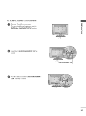
PREPARATION For 26/32/37/42LH20, 32/37/42/47LH30 1 Connect the cables as shown. 3 Put the cables inside the CABLE MANAGEMENT CLIP and snap it closed. CABLE MANAGEMENT CLIP 27 To connect additional equipment, see the EXTERNAL EQUIPMENT SETUP section. 2 Install the CABLE MANAGEMENT CLIP as necessary.
PREPARATION For 26/32/37/42LH20, 32/37/42/47LH30 1 Connect the cables as shown. 3 Put the cables inside the CABLE MANAGEMENT CLIP and snap it closed. CABLE MANAGEMENT CLIP 27 To connect additional equipment, see the EXTERNAL EQUIPMENT SETUP section. 2 Install the CABLE MANAGEMENT CLIP as necessary.
Owner's Manual (English)
Page 32
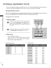
... = green, PB = blue, and PR = red). Y PB PR L R 2 Connect the audio output of the digital settop box to the owner's manual for 26/32/37/42LH20. EXTERNAL EQUIPMENT SETUP EXTERNAL EQUIPMENT SETUP I This part of EXTERNAL EQUIPMENT SETUP mainly use I Turn on the digital set -top box. I To prevent the... in any power cords until you do receive digital signals from a digital set-top box or other digital external device. HD RECEIVER SETUP This TV can receive digital over-the-air/digital cable signals without an external digital set -top box. (Refer to the COMPONENT IN VIDEO jacks on...
... = green, PB = blue, and PR = red). Y PB PR L R 2 Connect the audio output of the digital settop box to the owner's manual for 26/32/37/42LH20. EXTERNAL EQUIPMENT SETUP EXTERNAL EQUIPMENT SETUP I This part of EXTERNAL EQUIPMENT SETUP mainly use I Turn on the digital set -top box. I To prevent the... in any power cords until you do receive digital signals from a digital set-top box or other digital external device. HD RECEIVER SETUP This TV can receive digital over-the-air/digital cable signals without an external digital set -top box. (Refer to the COMPONENT IN VIDEO jacks on...
Owner's Manual (English)
Page 33
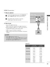
... the owner's manual for the digital set -top box to the HDMI/DVI I Select the HDMI or HDMI1/2*/3* input source on the TV using the INPUT button on the TV. 2 No separate audio connection is necessary. How to connect 1 Connect the digital set -top box.) I N or HDMI/DVI IN 1/2*/ 3* ...jack on the remote control. * HDMI 2: Except 19/22LH20, 22LH200C * HDMI 3: Except 19/22/26/32/37/42LH20, 19/22LU55, 32CL20 ! How to use the...
... the owner's manual for the digital set -top box to the HDMI/DVI I Select the HDMI or HDMI1/2*/3* input source on the TV using the INPUT button on the TV. 2 No separate audio connection is necessary. How to connect 1 Connect the digital set -top box.) I N or HDMI/DVI IN 1/2*/ 3* ...jack on the remote control. * HDMI 2: Except 19/22LH20, 22LH200C * HDMI 3: Except 19/22/26/32/37/42LH20, 19/22LU55, 32CL20 ! How to use the...
Owner's Manual (English)
Page 36
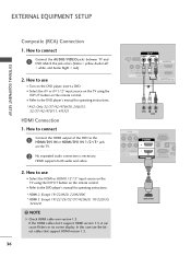
... to use I Select the A V or AV1/2* input source on the TV using the INPUT button on the DVD player, insert a DVD. How to the DVD player's manual for operating instructions. * AV2: Only 32/37/42/47LH30, 26LU55, 32/37/42/47LF11, 47LF21 HDMI Connection 1. In this case use I Refer to ...) Connection 1. Match the jack colors (Video = yellow, Audio Left = white, and Audio Right = red). 2. I Refer to connect 1 Connect the AUDIO/VIDEO jacks between TV and DVD. If the HDMI cables don't support HDMI version 1.3, it can cause flickers or no screen display. How to the DVD player's manual for...
... to use I Select the A V or AV1/2* input source on the TV using the INPUT button on the DVD player, insert a DVD. How to the DVD player's manual for operating instructions. * AV2: Only 32/37/42/47LH30, 26LU55, 32/37/42/47LF11, 47LF21 HDMI Connection 1. In this case use I Refer to ...) Connection 1. Match the jack colors (Video = yellow, Audio Left = white, and Audio Right = red). 2. I Refer to connect 1 Connect the AUDIO/VIDEO jacks between TV and DVD. If the HDMI cables don't support HDMI version 1.3, it can cause flickers or no screen display. How to the DVD player's manual for...

Owner's Manual (English)
Page 37
How to use I Insert a video tape into the VCR and press PLAY on the TV. 2 Connect the antenna cable to the RF antenna in socket of the VCR to the ANTENNA/CABLE IN socket on the VCR. (Refer to the ...same channel number. I Set VCR output switch to 3 or 4 and then tune TV to the VCR owner's manual.) ANT OUT S-VIDEO VIDEO L R AUDIO ANT IN OUTPUT SWITCH Wall Jack 2 Antenna 37 RGB IN (PC) AUDIO IN (RGB/DVI) OPTICAL DIGITAL AUDIO OUT 1 RS-232C IN ACNATBELNENIAN/ IN (CONTROL...
How to use I Insert a video tape into the VCR and press PLAY on the TV. 2 Connect the antenna cable to the RF antenna in socket of the VCR to the ANTENNA/CABLE IN socket on the VCR. (Refer to the ...same channel number. I Set VCR output switch to 3 or 4 and then tune TV to the VCR owner's manual.) ANT OUT S-VIDEO VIDEO L R AUDIO ANT IN OUTPUT SWITCH Wall Jack 2 Antenna 37 RGB IN (PC) AUDIO IN (RGB/DVI) OPTICAL DIGITAL AUDIO OUT 1 RS-232C IN ACNATBELNENIAN/ IN (CONTROL...
Owner's Manual (English)
Page 38
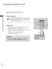
How to use I Insert a video tape into the VCR and press PLAY on the VCR. (Refer to the AUDIO L/MONO jack of the TV. USB IN SERVICE ONLY AV IN VIDEO AUDIO L(MONO) R 2 VIDEO L R AUDIO 1 COMPONENT IN /DVI 1 ANT IN S-VIDEO VIDEO L R AUDIO ANT OUT OUTPUT SWITCH 38 ...VCR owner's manual.) I Select the A V or AV1/2* input source on the TV using the INPUT button on the remote control. * AV2: Only 32/37/42/47LH30, 26LU55, 32/37/42/47LF11, 47LF21 ! How to connect 1 Connect the AUDIO/VIDEO jacks between TV and VCR. Match the jack colors (Video = yellow, Audio Left = white, ...
How to use I Insert a video tape into the VCR and press PLAY on the VCR. (Refer to the AUDIO L/MONO jack of the TV. USB IN SERVICE ONLY AV IN VIDEO AUDIO L(MONO) R 2 VIDEO L R AUDIO 1 COMPONENT IN /DVI 1 ANT IN S-VIDEO VIDEO L R AUDIO ANT OUT OUTPUT SWITCH 38 ...VCR owner's manual.) I Select the A V or AV1/2* input source on the TV using the INPUT button on the remote control. * AV2: Only 32/37/42/47LH30, 26LU55, 32/37/42/47LF11, 47LF21 ! How to connect 1 Connect the AUDIO/VIDEO jacks between TV and VCR. Match the jack colors (Video = yellow, Audio Left = white, ...
Owner's Manual (English)
Page 39
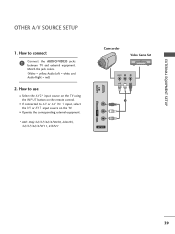
...input source on the remote control. EXTERNAL EQUIPMENT SETUP OTHER A/V SOURCE SETUP 1. How to connect 1 Connect the AUDIO/VIDEO jacks between TV and external equipment. Match the jack colors. (Video = yellow, Audio Left = white, and Audio Right = red) 2. I Select the A V 2* ...input source on the TV using the INPUT button on the TV. How to use I Operate the corresponding external equipment. * AV2: Only 32/37/42/47LH30, 26LU55, 32/37/42/47LF11, 47LF21 VIDEO L/MONO AUDIO R IN 3 Camcorder Video Game Set VIDEO L...
...input source on the remote control. EXTERNAL EQUIPMENT SETUP OTHER A/V SOURCE SETUP 1. How to connect 1 Connect the AUDIO/VIDEO jacks between TV and external equipment. Match the jack colors. (Video = yellow, Audio Left = white, and Audio Right = red) 2. I Select the A V 2* ...input source on the TV using the INPUT button on the TV. How to use I Operate the corresponding external equipment. * AV2: Only 32/37/42/47LH30, 26LU55, 32/37/42/47LF11, 47LF21 VIDEO L/MONO AUDIO R IN 3 Camcorder Video Game Set VIDEO L...
Owner's Manual (English)
Page 43
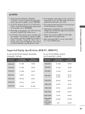
...be noise associated with the resolution, vertical pattern, contrast or brightness. Supported Display Specifications (RGB-PC, HDMI-PC) For 19/22/26/32/37/42LH20, 22LH200C, 19/26LU55, 32CL20 Resolution Horizontal Vertical Frequency(KHz) Frequency(Hz) 640x350 31.469 70.08 720x400 31.469 70.08 640x480 ..., change aspect ratio to DVI Cable is clear. G The synchronization input form for a long period of time. NOTES G 19/22/26/32/37/42LH20, 22LH200C, 19/26LU55, 32CL20: To get the the best picture quality, adjust the PC graphics card to 1360x768. If noise is present, ...
...be noise associated with the resolution, vertical pattern, contrast or brightness. Supported Display Specifications (RGB-PC, HDMI-PC) For 19/22/26/32/37/42LH20, 22LH200C, 19/26LU55, 32CL20 Resolution Horizontal Vertical Frequency(KHz) Frequency(Hz) 640x350 31.469 70.08 720x400 31.469 70.08 640x480 ..., change aspect ratio to DVI Cable is clear. G The synchronization input form for a long period of time. NOTES G 19/22/26/32/37/42LH20, 22LH200C, 19/26LU55, 32CL20: To get the the best picture quality, adjust the PC graphics card to 1360x768. If noise is present, ...

Owner's Manual (English)
Page 50
... If you do not complete the Initial setting, it was last set to switch the sound off with the AC power control switch on the TV, reset the Clock function. CHANNEL SELECTION 1 Press the CH ( or ) or NUMBER buttons to standby mode. VOLUME ADJUSTMENT Adjust the volume to suit... setting procedure is completed. I In standby mode to remember which power state it will appear whenever the TV is switched on the remote control. G If you intend to standby mode. At this moment, the TV switches to be away on TV (Except 19/22LH20, 22LH200C, 32/37/42/47LF11, 47LF21, 32CL20).
... If you do not complete the Initial setting, it was last set to switch the sound off with the AC power control switch on the TV, reset the Clock function. CHANNEL SELECTION 1 Press the CH ( or ) or NUMBER buttons to standby mode. VOLUME ADJUSTMENT Adjust the volume to suit... setting procedure is completed. I In standby mode to remember which power state it will appear whenever the TV is switched on the remote control. G If you intend to standby mode. At this moment, the TV switches to be away on TV (Except 19/22LH20, 22LH200C, 32/37/42/47LF11, 47LF21, 32CL20).
Owner's Manual (English)
Page 60
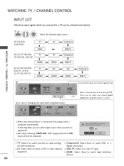
... input will not be activated and selected. 1 INPUT ENTER Select the desired input source. 19/22LH20, 22LH200C: TV HDMI 26/32/37/42LH20, TV 19/22LU55, 32CL20: HDMI2 32/37/42/47LH30, 26LU55, 47LF21, 32/37/42/47LF11: TV HDMI3 ie) AV AV HDMI1 AV1 HDMI2 Component RGB-PC Component RGB-PC AV2 Component HDMI1 RGB...
... input will not be activated and selected. 1 INPUT ENTER Select the desired input source. 19/22LH20, 22LH200C: TV HDMI 26/32/37/42LH20, TV 19/22LU55, 32CL20: HDMI2 32/37/42/47LH30, 26LU55, 47LF21, 32/37/42/47LF11: TV HDMI3 ie) AV AV HDMI1 AV1 HDMI2 Component RGB-PC Component RGB-PC AV2 Component HDMI1 RGB...

Owner's Manual (English)
Page 61
... RGB-PC HDMI1 HDMI2 HDMI3 Close 32/37/42/47LH30, 26LU55, 47LF21 32/37/42/47LF11 With using OPTION menu 1 MENU 2 ENTER Select OPTION. Select the label. 3 Return to TV viewing. RETURN Return to which input port. WATCHING TV / CHANNEL CONTROL INPUT LABEL This indicates ...which device is connected to TV viewing. Select Input Label. 3...
... RGB-PC HDMI1 HDMI2 HDMI3 Close 32/37/42/47LH30, 26LU55, 47LF21 32/37/42/47LF11 With using OPTION menu 1 MENU 2 ENTER Select OPTION. Select the label. 3 Return to TV viewing. RETURN Return to which input port. WATCHING TV / CHANNEL CONTROL INPUT LABEL This indicates ...which device is connected to TV viewing. Select Input Label. 3...


