Owners Manual
Page 2
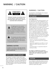
... 820-40 of important operating and maintenance (servicing) instructions in a residential installation. The lightning flash with the limits for help. NOTE TO CABLE/TV INSTALLER This reminder is intended to alert the user to radio communications. Increase the separation between the equipment and receiver. - Consult the dealer or an experienced radio/TV technician for a Class B digital device, pursuant to Part 15 of uninsulated...
... 820-40 of important operating and maintenance (servicing) instructions in a residential installation. The lightning flash with the limits for help. NOTE TO CABLE/TV INSTALLER This reminder is intended to alert the user to radio communications. Increase the separation between the equipment and receiver. - Consult the dealer or an experienced radio/TV technician for a Class B digital device, pursuant to Part 15 of uninsulated...

Owners Manual
Page 4
... grounding methods are dangerous. Check the specification page of the appliance, and have a qualified electrician install a separate circuit breaker. SAFETY INSTRUCTION 11 Never touch this apparatus or antenna during a thunder or lighting storm. 12 When mounting a TV on the wall, make the TV with wet hands. Do not pull on the power cord to plugs, wall outlets, and the point where...
... grounding methods are dangerous. Check the specification page of the appliance, and have a qualified electrician install a separate circuit breaker. SAFETY INSTRUCTION 11 Never touch this apparatus or antenna during a thunder or lighting storm. 12 When mounting a TV on the wall, make the TV with wet hands. Do not pull on the power cord to plugs, wall outlets, and the point where...

Owners Manual
Page 5
...-21) Ground Clamps Power Service Grounding Electrode System (NEC Art 250, Part H) 21 Cleaning When cleaning, unplug the power cord and scrub gently with respect to proper grounding of the mast and supporting structure, grounding of the lead-in wire to an antenna discharge unit, size of grounding conductors, location of the TV. 23 Ventilation Install your TV where there...
...-21) Ground Clamps Power Service Grounding Electrode System (NEC Art 250, Part H) 21 Cleaning When cleaning, unplug the power cord and scrub gently with respect to proper grounding of the mast and supporting structure, grounding of the lead-in wire to an antenna discharge unit, size of grounding conductors, location of the TV. 23 Ventilation Install your TV where there...

Owners Manual
Page 6
... Installation 19 Antenna or Cable Connection 20 EXTERNAL EQUIPMENT SETUP HD Receiver Setup 21 DVD Setup 24 VCR Setup 26 Other A/V Source Setup 28 Digital Audio Output 28 PC Setup 29 WATCHING TV / CHANNEL CONTROL Remote Control Functions 32 Turning On TV 34 Channel Selection 34 Volume Adjustment 34 On-Screen Menus Selection 35 Channel Setup 36 - EZ Picture - User Mode 47 Color Tone - Cinema Mode 50 Advanced - Movie Rating (MPAA) 77 Downloadable Rating 77 - Add / Delete Channel (Manual Scan 37 - Black (Darkness) Level 51 4 Picture Reset 52 Low-Power Picture Mode...
... Installation 19 Antenna or Cable Connection 20 EXTERNAL EQUIPMENT SETUP HD Receiver Setup 21 DVD Setup 24 VCR Setup 26 Other A/V Source Setup 28 Digital Audio Output 28 PC Setup 29 WATCHING TV / CHANNEL CONTROL Remote Control Functions 32 Turning On TV 34 Channel Selection 34 Volume Adjustment 34 On-Screen Menus Selection 35 Channel Setup 36 - EZ Picture - User Mode 47 Color Tone - Cinema Mode 50 Advanced - Movie Rating (MPAA) 77 Downloadable Rating 77 - Add / Delete Channel (Manual Scan 37 - Black (Darkness) Level 51 4 Picture Reset 52 Low-Power Picture Mode...
Owners Manual
Page 11
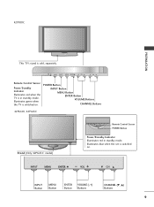
... INPUT Button MENU Button ENTER Button VOLUME Buttons CHANNEL Buttons 42PG60C, 42PG65C Stand (Only 42PG65C model) Remote Control Sensor POWER Button Power/Standby Indicator Illuminates red in standby mode. INPUT ENTER Illuminates blue when the set is switched on . INPUT MENU ENTER VOL CH Remote Control Sensor Power/Standby Indicator Illuminates red when the TV is sold, separately. INPUT MENU ENTER VOL CH INPUT MENU ENTER VOL CH INPUT MENU ENTER VOL CH INPUT Button MENU Button ENTER Button VOLUME (-,+) Buttons CHANNEL (E, D) Buttons 9 Illuminates green...
... INPUT Button MENU Button ENTER Button VOLUME Buttons CHANNEL Buttons 42PG60C, 42PG65C Stand (Only 42PG65C model) Remote Control Sensor POWER Button Power/Standby Indicator Illuminates red in standby mode. INPUT ENTER Illuminates blue when the set is switched on . INPUT MENU ENTER VOL CH Remote Control Sensor Power/Standby Indicator Illuminates red when the TV is sold, separately. INPUT MENU ENTER VOL CH INPUT MENU ENTER VOL CH INPUT MENU ENTER VOL CH INPUT Button MENU Button ENTER Button VOLUME (-,+) Buttons CHANNEL (E, D) Buttons 9 Illuminates green...
Owners Manual
Page 13
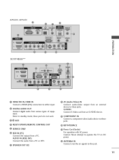
... AV IN 1 VIDEO AUDIO COMPONENT IN 9 S-VIDEO 5 AUDIO L/MONO VIDEO 8 1 HDMI/DVI IN, HDMI IN Connect a HDMI (DVI) connection to this jack. 11 Note: In standby mode, these jacks. 10 RJP INTERFACE 11 Power Cord Socket For operation with AC power. S-VIDEO Connect S-Video out from a PC. AUDIO IN (RGB, DVI) Connect the audio from a PC or DTV. 7 SPEAKER OUT 8Ω 8 AV (Audio/Video) IN Connect audio/video output from an external device to these ports do not work. 3 13 M.P.I 4 RESET/UPDATE/REMOTE CONTROL OUT 5 SERVICE ONLY 6 RGB...
... AV IN 1 VIDEO AUDIO COMPONENT IN 9 S-VIDEO 5 AUDIO L/MONO VIDEO 8 1 HDMI/DVI IN, HDMI IN Connect a HDMI (DVI) connection to this jack. 11 Note: In standby mode, these jacks. 10 RJP INTERFACE 11 Power Cord Socket For operation with AC power. S-VIDEO Connect S-Video out from a PC. AUDIO IN (RGB, DVI) Connect the audio from a PC or DTV. 7 SPEAKER OUT 8Ω 8 AV (Audio/Video) IN Connect audio/video output from an external device to these ports do not work. 3 13 M.P.I 4 RESET/UPDATE/REMOTE CONTROL OUT 5 SERVICE ONLY 6 RGB...
Owners Manual
Page 23
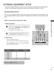
.../37/42LG5***) models. HD RECEIVER SETUP This TV can receive Digital Over-the-air/Cable signals without an external digital set . 2. How to connect 1 Connect the video outputs (Y, PB, PR) of the digital set-top box to the COMPONENT IN VIDEO jacks on the set. Y PB PR L R Connect the audio output of the digital set top box to 2 the COMPONENT IN AUDIO jacks on the digital set -top box.) ■ Select Component input source with using the INPUT button on the remote control. HDMI/DVI IN 1(DVI) 1 2 DIGITAL AUDIO OUT (OPTICAL) 2 M.P.I. However, if...
.../37/42LG5***) models. HD RECEIVER SETUP This TV can receive Digital Over-the-air/Cable signals without an external digital set . 2. How to connect 1 Connect the video outputs (Y, PB, PR) of the digital set-top box to the COMPONENT IN VIDEO jacks on the set. Y PB PR L R Connect the audio output of the digital set top box to 2 the COMPONENT IN AUDIO jacks on the digital set -top box.) ■ Select Component input source with using the INPUT button on the remote control. HDMI/DVI IN 1(DVI) 1 2 DIGITAL AUDIO OUT (OPTICAL) 2 M.P.I. However, if...
Owners Manual
Page 24
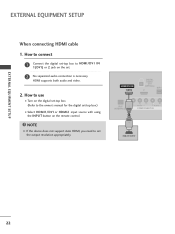
... SETUP EXTERNAL EQUIPMENT SETUP When connecting HDMI cable 1. How to connect 1 Connect the digital set-top box to HDMI/DVI IN 1(DVI) or 2 jack on the remote control. NOTE G If the device does not support Auto HDMI, you need to the owner's manual for the digital set-top box.) ■ Select HDMI1/DVI or HDMI2 input source with using the INPUT button on the set the output resolution appropriately. HDMI supports both audio and video. 2. How to use ■ Turn on the digital set-top box. ( ) (Refer to set . 2 No separated audio connection...
... SETUP EXTERNAL EQUIPMENT SETUP When connecting HDMI cable 1. How to connect 1 Connect the digital set-top box to HDMI/DVI IN 1(DVI) or 2 jack on the remote control. NOTE G If the device does not support Auto HDMI, you need to the owner's manual for the digital set-top box.) ■ Select HDMI1/DVI or HDMI2 input source with using the INPUT button on the set the output resolution appropriately. HDMI supports both audio and video. 2. How to use ■ Turn on the digital set-top box. ( ) (Refer to set . 2 No separated audio connection...

Owners Manual
Page 25
... the HDMI/DVI IN 1(DVI) or 2 jack on the set. 2 Connect the audio output of the digital set . 2. How to use ■ Turn on the digital set-top box. (Refer to the owner's manual for the digital set-top box.) ■ Select HDMI1/DVI or HDMI2 input source with using the INPUT button on the set -top box to DVI cable HDMI/DVI IN 1(DVI) DIGITAL AUDIO OUT (OPTICAL) 2 M.P.I. EXTERNAL EQUIPMENT SETUP When connecting HDMI to the AUDIO IN (RGB,DVI) jack on the remote control...
... the HDMI/DVI IN 1(DVI) or 2 jack on the set. 2 Connect the audio output of the digital set . 2. How to use ■ Turn on the digital set-top box. (Refer to the owner's manual for the digital set-top box.) ■ Select HDMI1/DVI or HDMI2 input source with using the INPUT button on the set -top box to DVI cable HDMI/DVI IN 1(DVI) DIGITAL AUDIO OUT (OPTICAL) 2 M.P.I. EXTERNAL EQUIPMENT SETUP When connecting HDMI to the AUDIO IN (RGB,DVI) jack on the remote control...

Owners Manual
Page 26
... the DVD to the 2 COMPONENT IN AUDIO jacks on the set . 2. Component ports on the TV Y Y Video output ports Y on the remote control. ■ Refer to the COMPONENT IN VIDEO jacks on the set . Match the jack colors (Y = green, PB = blue, and PR = red). RJP ERFACE VIDEO AUDIO S-VIDEO ( ) COMPONENT IN Component Input ports To get better picture quality, connect a DVD player to use ■ Turn on the DVD player, insert a DVD. HDMI/DVI IN 1(DVI) 1 2 DIGITAL AUDIO OUT (OPTICAL) 2 M.P.I. ■ Select Component input source with using the INPUT button on DVD player...
... the DVD to the 2 COMPONENT IN AUDIO jacks on the set . 2. Component ports on the TV Y Y Video output ports Y on the remote control. ■ Refer to the COMPONENT IN VIDEO jacks on the set . Match the jack colors (Y = green, PB = blue, and PR = red). RJP ERFACE VIDEO AUDIO S-VIDEO ( ) COMPONENT IN Component Input ports To get better picture quality, connect a DVD player to use ■ Turn on the DVD player, insert a DVD. HDMI/DVI IN 1(DVI) 1 2 DIGITAL AUDIO OUT (OPTICAL) 2 M.P.I. ■ Select Component input source with using the INPUT button on DVD player...

Owners Manual
Page 27
...input source. ■ Refer to use HDMI/DVI IN 1(DVI) DIGITAL AUDIO OUT (OPTICAL) 2 M.P.I . How to connect 1 Connect the HDMI output of the DVD to the S -VIDEO input on the set. 2. HDMI supports both audio and video. 2. S REMOTE CONTROL UPDATE OUT AUDIO NT IN S-VIDEO (MONO) AUDIO AV IN 1 VIDEO SPE O When connecting HDMI cable 1. How to the DVD player's manual for operating instructions. HDMI-DVD OUTPUT 25 RJP INTERFACE VIDEO AUDIO COMPONENT IN 1 NOTE G If the device does not support Auto HDMI, you need to the DVD player's manual for operating instructions...
...input source. ■ Refer to use HDMI/DVI IN 1(DVI) DIGITAL AUDIO OUT (OPTICAL) 2 M.P.I . How to connect 1 Connect the HDMI output of the DVD to the S -VIDEO input on the set. 2. HDMI supports both audio and video. 2. S REMOTE CONTROL UPDATE OUT AUDIO NT IN S-VIDEO (MONO) AUDIO AV IN 1 VIDEO SPE O When connecting HDMI cable 1. How to the DVD player's manual for operating instructions. HDMI-DVD OUTPUT 25 RJP INTERFACE VIDEO AUDIO COMPONENT IN 1 NOTE G If the device does not support Auto HDMI, you need to the DVD player's manual for operating instructions...
Owners Manual
Page 29
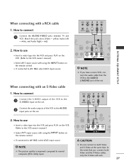
... owner's manual.) ■ Select A V 1 input source with an S-Video cable ANT OUT OUTPUT SWITCH TAL DIO UT CAL) M.P.I . 1 Connect the S-VIDEO output of the VCR to the AUDIO input jacks on the remote control. ■ If connected to connect M.P.I . How to normal composite (RCA cable) input. SER REMOTE CONTROL UPDATE OUT ■ Insert a video tape into the VCR and press PLAY on the VCR. (Refer to the S -VIDEO input on the remote control. When connecting with using the INPUT button on the set...
... owner's manual.) ■ Select A V 1 input source with an S-Video cable ANT OUT OUTPUT SWITCH TAL DIO UT CAL) M.P.I . 1 Connect the S-VIDEO output of the VCR to the AUDIO input jacks on the remote control. ■ If connected to connect M.P.I . How to normal composite (RCA cable) input. SER REMOTE CONTROL UPDATE OUT ■ Insert a video tape into the VCR and press PLAY on the VCR. (Refer to the S -VIDEO input on the remote control. When connecting with using the INPUT button on the set...
Owners Manual
Page 30
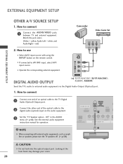
... TV Digital Audio (Optical) Output port. 2 Connect the other end of the optical cable to AV IN1 input, select A V 1 input source. ■ Operate the corresponding external equipment. Off" in the AUDIO menu. (G p.58). Match the jack colors. (Video = yellow, Audio Left = white, and Audio Right = red) Camcorder Video Game Set VIDEO L R 2. Looking at the laser beam may damage your vision. 28 HDMI/DVI IN 1(DVI) DIGITAL AUDIO OUT (OPTICAL) 2 M.P.I. 1 ( RJP VIDEO AUDIO S-V NTERFACE COMPONENT IN 2 NOTE G When connecting with using the INPUT button on the remote control...
... TV Digital Audio (Optical) Output port. 2 Connect the other end of the optical cable to AV IN1 input, select A V 1 input source. ■ Operate the corresponding external equipment. Off" in the AUDIO menu. (G p.58). Match the jack colors. (Video = yellow, Audio Left = white, and Audio Right = red) Camcorder Video Game Set VIDEO L R 2. Looking at the laser beam may damage your vision. 28 HDMI/DVI IN 1(DVI) DIGITAL AUDIO OUT (OPTICAL) 2 M.P.I. 1 ( RJP VIDEO AUDIO S-V NTERFACE COMPONENT IN 2 NOTE G When connecting with using the INPUT button on the remote control...
Owners Manual
Page 31
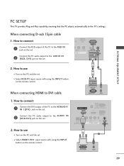
... the remote control. How to use ■ Turn on the PC and the set 2 ■ Select HDMI1/DVI input source with using the INPUT button on the set . HDMI/DVI IN 1(DVI) DIGITA AUDIO OUT (OPTICA VICE ONLY 2 Connect the PC audio output to DVI cable RGB OUTPUT AUDIO 1. How to connect SERVICE ONLY REMOTE CONTROL ATE OUT ( ) ( ) RGB IN 1 Connect the RGB output of the PC to the TV's settings. RGB IN ( ) ( ) RJP INTERFACE VIDEO ER AUDIO COMPONENT...
... the remote control. How to use ■ Turn on the PC and the set 2 ■ Select HDMI1/DVI input source with using the INPUT button on the set . HDMI/DVI IN 1(DVI) DIGITA AUDIO OUT (OPTICA VICE ONLY 2 Connect the PC audio output to DVI cable RGB OUTPUT AUDIO 1. How to connect SERVICE ONLY REMOTE CONTROL ATE OUT ( ) ( ) RGB IN 1 Connect the RGB output of the PC to the TV's settings. RGB IN ( ) ( ) RJP INTERFACE VIDEO ER AUDIO COMPONENT...
Owners Manual
Page 32
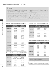
.... EXTERNAL EQUIPMENT SETUP NOTES G Depending on the graphics card, DOS mode may not work if a HDMI to another rate or adjust the brightness and contrast on the VIDEO menu until the picture is clear. G Avoid keeping a fixed image on your TV. The fixed image may be changed, change the refresh rate to DVI Cable is separate. If noise is present, change the PC output to another resolution, change...
.... EXTERNAL EQUIPMENT SETUP NOTES G Depending on the graphics card, DOS mode may not work if a HDMI to another rate or adjust the brightness and contrast on the VIDEO menu until the picture is clear. G Avoid keeping a fixed image on your TV. The fixed image may be changed, change the refresh rate to DVI Cable is separate. If noise is present, change the PC output to another resolution, change...

Owners Manual
Page 34
... and Component input sources. Changes the PIP channel. G p.42 VCR/DVD Control video cassette recorders or DVD players. PIP CH + PIP INPUT EZ PIC EZ SOUND SWAP INFO CC EXIT MENU RATIO SAP ENTER VOL TIMER MUTE CH PAGE 1 2 3 4 5 6 7 8 9 0 FLASH BACK 32 G p.55 SWAP(or PIP SWAP) Exchange the main/sub images. control buttons NUMBER button - (DASH) Used to enter a program number for the sub-picture. INPUT TV POWER MODE TV INPUT DVD MULTI VCR PIP PIP CH - G p.42 PIP INPUT Select the connected input source for multiple program channels such...
... and Component input sources. Changes the PIP channel. G p.42 VCR/DVD Control video cassette recorders or DVD players. PIP CH + PIP INPUT EZ PIC EZ SOUND SWAP INFO CC EXIT MENU RATIO SAP ENTER VOL TIMER MUTE CH PAGE 1 2 3 4 5 6 7 8 9 0 FLASH BACK 32 G p.55 SWAP(or PIP SWAP) Exchange the main/sub images. control buttons NUMBER button - (DASH) Used to enter a program number for the sub-picture. INPUT TV POWER MODE TV INPUT DVD MULTI VCR PIP PIP CH - G p.42 PIP INPUT Select the connected input source for multiple program channels such...
Owners Manual
Page 37
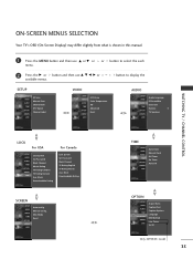
...XGA Mode Reset TIME SETUP VIDEO AUDIO TIME OPTION SCREEN LOCK Auto Clock Manual Clock Off Timer On Timer Auto Off OPTION SETUP VIDEO AUDIO TIME OPTION SCREEN LOCK Aspect Ratio Caption/Text Caption Options Language ISM Method Low Power Set ID Only 42PX8DC model 35 button to select the each 2 Press the G or button and then use D or E or menu. or button to display the SETUP SETUP VIDEO AUDIO TIME OPTION SCREEN LOCK EZ Scan Manual Scan Channel Edit DTV Signal Channel Label VIDEO SETUP VIDEO AUDIO TIME OPTION SCREEN LOCK EZ Picture Color Temperature XD Advanced Reset AUDIO...
...XGA Mode Reset TIME SETUP VIDEO AUDIO TIME OPTION SCREEN LOCK Auto Clock Manual Clock Off Timer On Timer Auto Off OPTION SETUP VIDEO AUDIO TIME OPTION SCREEN LOCK Aspect Ratio Caption/Text Caption Options Language ISM Method Low Power Set ID Only 42PX8DC model 35 button to select the each 2 Press the G or button and then use D or E or menu. or button to display the SETUP SETUP VIDEO AUDIO TIME OPTION SCREEN LOCK EZ Scan Manual Scan Channel Edit DTV Signal Channel Label VIDEO SETUP VIDEO AUDIO TIME OPTION SCREEN LOCK EZ Picture Color Temperature XD Advanced Reset AUDIO...
Owners Manual
Page 76
... initial password "0-0-0-0". Most television programs and television movies can be blocked by broadcasting stations. Enable the lock V-Chip rating and categories Rating guidelines are provided by TV Rating and/or Individual Categories. To use this menu. 1 Press the MENU button and then use the Movie Rating System (MPAA) only. Set ratings and categories to be used to block specific channels, ratings, and external viewing sources. The Parental Control Function...
... initial password "0-0-0-0". Most television programs and television movies can be blocked by broadcasting stations. Enable the lock V-Chip rating and categories Rating guidelines are provided by TV Rating and/or Individual Categories. To use this menu. 1 Press the MENU button and then use the Movie Rating System (MPAA) only. Set ratings and categories to be used to block specific channels, ratings, and external viewing sources. The Parental Control Function...

Owners Manual
Page 78
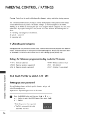
... watch or that you have hooked up. Block G Downloadable Rating AV1 AV2 Component RGB HDMI1/DVI HDMI2 1 On On Off Off On Off 23 ing or press MENU button to return to TV view- Block Downloadable Rating For Canada Lock System Set Password Block Channel TV Rating-English TV Rating-French Aux. PARENTAL CONTROL / RATING 1 After inputting the password, use the ENTER button to block or unblock...
... watch or that you have hooked up. Block G Downloadable Rating AV1 AV2 Component RGB HDMI1/DVI HDMI2 1 On On Off Off On Off 23 ing or press MENU button to return to TV view- Block Downloadable Rating For Canada Lock System Set Password Block Channel TV Rating-English TV Rating-French Aux. PARENTAL CONTROL / RATING 1 After inputting the password, use the ENTER button to block or unblock...

Owners Manual
Page 86
... case, you don't press any button for two seconds; The programming procedures are explained below. 2 Press the MENU and MUTE button continuously at a time. When pressing the button, the light blinks at the same time for 20 seconds, the light on the mode button will be programmed to store the code. APPENDIX PROGRAMMING THE REMOTE CONTROL The provided universal remote control can operate each device without programming, turn on the device (such as...
... case, you don't press any button for two seconds; The programming procedures are explained below. 2 Press the MENU and MUTE button continuously at a time. When pressing the button, the light blinks at the same time for 20 seconds, the light on the mode button will be programmed to store the code. APPENDIX PROGRAMMING THE REMOTE CONTROL The provided universal remote control can operate each device without programming, turn on the device (such as...


