Owner's Manual (English)
Page 6
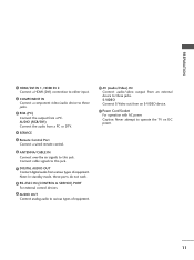
...a Wall 16 Antenna or Cable Connection 17 EXTERNAL EQUIPMENT SETUP HD Receiver Setup 18 DVD Setup 21 VCR Setup 23 Other A/V Source Setup 25 PC Setup 26 Audio Out Setup 31 WATCHING TV / CHANNEL CONTROL Remote Control Functions 32 Turning On TV 34 Channel Selection 34 Volume Adjustment 34 On-Screen Menus Selection 35 Channel Setup - User Mode 47 - Channel Editing 38 Input List 39 SimpLink 40 Input Label 42 Key Lock 43 4 PICTURE CONTROL Picture Size (Aspect Ratio) Control 44 Preset Picture Settings - Preset 45 Color Tone - Preset 46 Manual Picture Adjustment - Black...
...a Wall 16 Antenna or Cable Connection 17 EXTERNAL EQUIPMENT SETUP HD Receiver Setup 18 DVD Setup 21 VCR Setup 23 Other A/V Source Setup 25 PC Setup 26 Audio Out Setup 31 WATCHING TV / CHANNEL CONTROL Remote Control Functions 32 Turning On TV 34 Channel Selection 34 Volume Adjustment 34 On-Screen Menus Selection 35 Channel Setup - User Mode 47 - Channel Editing 38 Input List 39 SimpLink 40 Input Label 42 Key Lock 43 4 PICTURE CONTROL Picture Size (Aspect Ratio) Control 44 Preset Picture Settings - Preset 45 Color Tone - Preset 46 Manual Picture Adjustment - Black...
Owner's Manual (English)
Page 8
...-ratio screens, and AC3 digital audio. High-definition television. It has 2 HDMI ports that connect audio and video devices with TV. This is normal, there is turned on the screen, appearing as tiny red, green, or blue spots. Doing so may produce some temporary distortion effects on the monitor's performance. With HDMI CEC support of your finger(s) against it is nothing wrong with one remote control. I If the TV feels...
...-ratio screens, and AC3 digital audio. High-definition television. It has 2 HDMI ports that connect audio and video devices with TV. This is normal, there is turned on the screen, appearing as tiny red, green, or blue spots. Doing so may produce some temporary distortion effects on the monitor's performance. With HDMI CEC support of your finger(s) against it is nothing wrong with one remote control. I If the TV feels...
Owner's Manual (English)
Page 11
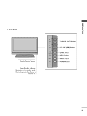
CH VOL ENTER MENU INPUT CH VOL ENTER MENU INPUT CHANNEL (D,E)Buttons VOLUME (F,G)Buttons ENTER Button MENU Button INPUT Button POWER Button 9 Illuminates green when the set is switched on. PREPARATION LCD TV Model Remote Control Sensor Power/Standby Indicator Illuminates red in standby mode.
CH VOL ENTER MENU INPUT CH VOL ENTER MENU INPUT CHANNEL (D,E)Buttons VOLUME (F,G)Buttons ENTER Button MENU Button INPUT Button POWER Button 9 Illuminates green when the set is switched on. PREPARATION LCD TV Model Remote Control Sensor Power/Standby Indicator Illuminates red in standby mode.
Owner's Manual (English)
Page 13
.... 9 AUDIO OUT Connect analog audio to various types of equipment. S-VIDEO Connect S-Video out from a PC or DTV. 4 SERVICE 5 Remote Control Port Connect a wired remote control. 6 ANTENNA/CABLE IN Connect over-the air signals to this jack. AUDIO (RGB/DVI) Connect the audio from an S-VIDEO device. 11 Power Cord Socket For operation with AC power. Connect cable signals to this jack. 7 DIGITAL AUDIO OUT Connect digital audio from various types of equipment. 10 AV (Audio/Video) IN Connect audio/video output from a PC. Caution: Never attempt to these jacks. Note: In standby mode...
.... 9 AUDIO OUT Connect analog audio to various types of equipment. S-VIDEO Connect S-Video out from a PC or DTV. 4 SERVICE 5 Remote Control Port Connect a wired remote control. 6 ANTENNA/CABLE IN Connect over-the air signals to this jack. AUDIO (RGB/DVI) Connect the audio from an S-VIDEO device. 11 Power Cord Socket For operation with AC power. Connect cable signals to this jack. 7 DIGITAL AUDIO OUT Connect digital audio from various types of equipment. 10 AV (Audio/Video) IN Connect audio/video output from a PC. Caution: Never attempt to these jacks. Note: In standby mode...
Owner's Manual (English)
Page 15
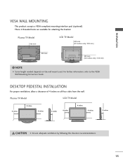
... available for attaching the bracket. For further information, refer to the VESA Wall Mounting Instruction Guide. ( ) DESKTOP PEDESTAL INSTALLATION ( ) For proper ventilation, allow a clearance of 4 inches on the wall mount used. Plasma TV Model LCD TV Model 4 inches 4 inches 4 inches 4 inches 4 inches 4 inches 4 inches 4 inches CAUTION G Ensure adequate ventilation by following the clearance recommendations. 13 NOTE G Screw length needed depends on all four sides from the wall. Plasma TV Model 600 mm LCD TV Model 600 mm (32 inches only: 200 mm) R R 400...
... available for attaching the bracket. For further information, refer to the VESA Wall Mounting Instruction Guide. ( ) DESKTOP PEDESTAL INSTALLATION ( ) For proper ventilation, allow a clearance of 4 inches on the wall mount used. Plasma TV Model LCD TV Model 4 inches 4 inches 4 inches 4 inches 4 inches 4 inches 4 inches 4 inches CAUTION G Ensure adequate ventilation by following the clearance recommendations. 13 NOTE G Screw length needed depends on all four sides from the wall. Plasma TV Model 600 mm LCD TV Model 600 mm (32 inches only: 200 mm) R R 400...
Owner's Manual (English)
Page 20
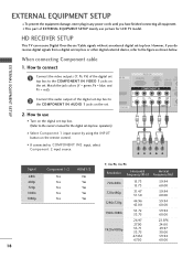
... COMPONENT IN VIDEO 1 jacks on the digital set-top box. (Refer to the owner's manual for LCD TV model. HD RECEIVER SETUP This TV can receive Digital Over-the-air/Cable signals without an external digital set . operation) I Select Component 1 input source by using the INPUT button on the set -top box. When connecting Component cable 1. I If connected to 1 the COMPONENT IN AUDIO 1 jacks on the remote control. 1 2 I This part of the digital set top box to use picture for the digital set . Match the jack colors (Y = green, PB = blue, and PR = red). RGB IN RGB(PC) AUDIO...
... COMPONENT IN VIDEO 1 jacks on the digital set-top box. (Refer to the owner's manual for LCD TV model. HD RECEIVER SETUP This TV can receive Digital Over-the-air/Cable signals without an external digital set . operation) I Select Component 1 input source by using the INPUT button on the set -top box. When connecting Component cable 1. I If connected to 1 the COMPONENT IN AUDIO 1 jacks on the remote control. 1 2 I This part of the digital set top box to use picture for the digital set . Match the jack colors (Y = green, PB = blue, and PR = red). RGB IN RGB(PC) AUDIO...
Owner's Manual (English)
Page 21
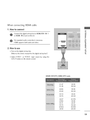
...use I Turn on the digital set-top box. (Refer to HDMI/DVI IN 1 or HDMI IN 2 jack on the set -top box.) I Select HDMI1 or HDMI2 input source by using the INPUT button on the remote control. HDMI IN RGB IN RGB(PC) AUDIO (RGB/D 2 2 1 1 HDMI/DVI IN COMPONENT IN VIDEO 1 HDMI-DTV OUTPUT HDMI1/DVI-DTV, HDMI2-DTV mode Resolution...60.00 19 How to connect 1 Connect the digital set-top box to the owner's manual for the digital set . 2 No separated audio connection is necessary. HDMI supports both audio and video. ( ) 2. EXTERNAL EQUIPMENT SETUP When connecting HDMI cable 1.
...use I Turn on the digital set-top box. (Refer to HDMI/DVI IN 1 or HDMI IN 2 jack on the set -top box.) I Select HDMI1 or HDMI2 input source by using the INPUT button on the remote control. HDMI IN RGB IN RGB(PC) AUDIO (RGB/D 2 2 1 1 HDMI/DVI IN COMPONENT IN VIDEO 1 HDMI-DTV OUTPUT HDMI1/DVI-DTV, HDMI2-DTV mode Resolution...60.00 19 How to connect 1 Connect the digital set-top box to the owner's manual for the digital set . 2 No separated audio connection is necessary. HDMI supports both audio and video. ( ) 2. EXTERNAL EQUIPMENT SETUP When connecting HDMI cable 1.
Owner's Manual (English)
Page 22
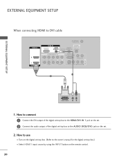
... owner's manual for the digital set-top box.) I Select HDMI1 input source by using the INPUT button on the set -top box to the AUDIO (RGB/DVI) jack on the remote control. 20 EXTERNAL EQUIPMENT SETUP EXTERNAL EQUIPMENT SETUP When connecting HDMI to the HDMI/DVI IN 1 jack on the set. 2 Connect the audio output of the digital set-top box to DVI cable HDMI IN ANTENNA/ CABLE IN RGB IN DIGITAL RGB(PC) AUDIO REMOTE AUDIO OUT (RGB/DVI) SERVICE CONTROL IN OPTICAL 2 2 1 1 HDMI/DVI IN COMPONENT IN RS-232C IN (CONTROL & SERVICE) AUDIO...
... owner's manual for the digital set-top box.) I Select HDMI1 input source by using the INPUT button on the set -top box to the AUDIO (RGB/DVI) jack on the remote control. 20 EXTERNAL EQUIPMENT SETUP EXTERNAL EQUIPMENT SETUP When connecting HDMI to the HDMI/DVI IN 1 jack on the set. 2 Connect the audio output of the digital set-top box to DVI cable HDMI IN ANTENNA/ CABLE IN RGB IN DIGITAL RGB(PC) AUDIO REMOTE AUDIO OUT (RGB/DVI) SERVICE CONTROL IN OPTICAL 2 2 1 1 HDMI/DVI IN COMPONENT IN RS-232C IN (CONTROL & SERVICE) AUDIO...
Owner's Manual (English)
Page 23
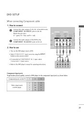
... the remote control. Y PB PR L R Component Input ports To get better picture quality, connect a DVD player to use 1 VI IN VIDEO AUDIO S-VI ( ) I Select Component 1 input source by using the INPUT button on the DVD player, insert a DVD. DVD SETUP When connecting Component cable 1. Component ports on the TV Y PB PR Video output ports on the set . How to connect EXTERNAL EQUIPMENT SETUP 1 Connect the video outputs (Y, PB, PR) of the DVD to the DVD player's manual for operating instructions. Match the jack colors IN (Y = green, PB = blue, and PR = red).
... the remote control. Y PB PR L R Component Input ports To get better picture quality, connect a DVD player to use 1 VI IN VIDEO AUDIO S-VI ( ) I Select Component 1 input source by using the INPUT button on the DVD player, insert a DVD. DVD SETUP When connecting Component cable 1. Component ports on the TV Y PB PR Video output ports on the set . How to connect EXTERNAL EQUIPMENT SETUP 1 Connect the video outputs (Y, PB, PR) of the DVD to the DVD player's manual for operating instructions. Match the jack colors IN (Y = green, PB = blue, and PR = red).
Owner's Manual (English)
Page 24
... REMOTE AUDIO OUT DVI) SERVICE CONTROL IN OPTICAL N RS-232C IN (CONTROL & SERVICE) AUDIO OUT AUDIO S-VIDEO VIDEO (MONO) AUDIO AV IN 1 When connecting HDMI cable 1. I Turn on the remote control. HDMI IN RGB IN RGB(PC) AUDIO (RGB/DVI 2 2 1 1 HDMI/DVI IN COMPONENT IN VIDEO A 1 HDMI-DVD OUTPUT 22 I If connected to the AUDIO input jacks on the set. 2. How to the HDMI/DVI IN 1 or HDMI IN 2 jack on the remote control. I Refer to the DVD player's manual for operating instructions. HDMI suppo( rt)s both audio and video. 2. EXTERNAL EQUIPMENT SETUP...
... REMOTE AUDIO OUT DVI) SERVICE CONTROL IN OPTICAL N RS-232C IN (CONTROL & SERVICE) AUDIO OUT AUDIO S-VIDEO VIDEO (MONO) AUDIO AV IN 1 When connecting HDMI cable 1. I Turn on the remote control. HDMI IN RGB IN RGB(PC) AUDIO (RGB/DVI 2 2 1 1 HDMI/DVI IN COMPONENT IN VIDEO A 1 HDMI-DVD OUTPUT 22 I If connected to the AUDIO input jacks on the set. 2. How to the HDMI/DVI IN 1 or HDMI IN 2 jack on the remote control. I Refer to the DVD player's manual for operating instructions. HDMI suppo( rt)s both audio and video. 2. EXTERNAL EQUIPMENT SETUP...

Owner's Manual (English)
Page 26
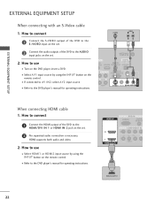
...RCA cable) input. NOTE G The picture quality is improved: compared to the VCR owner's manual.) I Insert a video tape into the VCR and press PLAY on the remote control. Match the jack colors (Video = yellow, Audio Left = white, and Audio Right = red) 2. ANT IN S-VIDEO VIDEO L R ANT OUT OUTPUT SWITCH 1 ANTENNA/ CABLE IN DIGITAL UDIO REMOTE AUDIO OUT B/DVI) SERVICE CONTROL IN OPTICAL T IN RS-232C IN (CONTROL & SERVICE) ( ) AUDIO OUT AUDIO S-VIDEO VIDEO (MONO) AUDIO AV IN 1 ! ( ) EXTERNAL EQUIPMENT SETUP EXTERNAL EQUIPMENT SETUP When connecting with an S-Video cable 1.
...RCA cable) input. NOTE G The picture quality is improved: compared to the VCR owner's manual.) I Insert a video tape into the VCR and press PLAY on the remote control. Match the jack colors (Video = yellow, Audio Left = white, and Audio Right = red) 2. ANT IN S-VIDEO VIDEO L R ANT OUT OUTPUT SWITCH 1 ANTENNA/ CABLE IN DIGITAL UDIO REMOTE AUDIO OUT B/DVI) SERVICE CONTROL IN OPTICAL T IN RS-232C IN (CONTROL & SERVICE) ( ) AUDIO OUT AUDIO S-VIDEO VIDEO (MONO) AUDIO AV IN 1 ! ( ) EXTERNAL EQUIPMENT SETUP EXTERNAL EQUIPMENT SETUP When connecting with an S-Video cable 1.
Owner's Manual (English)
Page 28
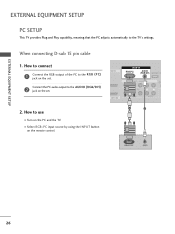
... input source by using the INPUT button on the set . Connect the PC audio output to the R GB (P C) jack on the PC and the TV. How to connect 1 Connect the RGB output of the PC to the AUDIO (RGB/DVI) 2 jack on the remote control. EXTERNAL EQUIPMENT SETUP EXTERNAL EQUIPMENT SETUP PC SETUP This TV provides Plug and Play capability, meaning that the PC adjusts automatically to use I /DVI IN VIDEO AUDIO 1 2 RGB OUTPUT AUDIO 26 When connecting D-sub 15 pin cable...
... input source by using the INPUT button on the set . Connect the PC audio output to the R GB (P C) jack on the PC and the TV. How to connect 1 Connect the RGB output of the PC to the AUDIO (RGB/DVI) 2 jack on the remote control. EXTERNAL EQUIPMENT SETUP EXTERNAL EQUIPMENT SETUP PC SETUP This TV provides Plug and Play capability, meaning that the PC adjusts automatically to use I /DVI IN VIDEO AUDIO 1 2 RGB OUTPUT AUDIO 26 When connecting D-sub 15 pin cable...
Owner's Manual (English)
Page 31
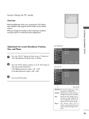
... For LCD TV Resolution Position Size Phase 1024 x 768 1280 x 768 1360 x 768 1366 x 768 Reset D MENU Prev E Select Ok 123 Resolution This function allows you prefer. Screen Setup for screen Resolution, Position, Size, and Phase 1 Press the ADJUST button and then use D or E button to select Resolution, Position, Size, or Phase. 2 Press the ENTER button and then use D E F G button to see the best picture appearance. Position This function is to adjust picture to a PC Output...
... For LCD TV Resolution Position Size Phase 1024 x 768 1280 x 768 1360 x 768 1366 x 768 Reset D MENU Prev E Select Ok 123 Resolution This function allows you prefer. Screen Setup for screen Resolution, Position, Size, and Phase 1 Press the ADJUST button and then use D or E button to select Resolution, Position, Size, or Phase. 2 Press the ENTER button and then use D E F G button to see the best picture appearance. Position This function is to adjust picture to a PC Output...
Owner's Manual (English)
Page 33
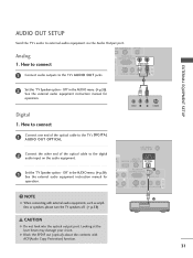
... SETUP AUDIO OUT SETUP Send the TV's audio to the digital audio input on the audio equipment. 3 Set the "TV Speaker option - See the external audio equipment instruction manual for operation. ! NOTE G When connecting with ACP(Audio Copy Protection) function. 31 How to connect S-VIDEO VIDEO (MONO) AUDIO 1 VIDEO L R S-VIDEO 1 Connect one end of the optical cable to the TV's DIGITAL AUDIO OUT OPTICAL. 2 Connect the other end of the optical cable to external audio equipment via the Audio Output port. How to connect RS-232C IN (CONTROL & SERVICE) AUDIO OUT AV IN 1 1 Connect...
... SETUP AUDIO OUT SETUP Send the TV's audio to the digital audio input on the audio equipment. 3 Set the "TV Speaker option - See the external audio equipment instruction manual for operation. ! NOTE G When connecting with ACP(Audio Copy Protection) function. 31 How to connect S-VIDEO VIDEO (MONO) AUDIO 1 VIDEO L R S-VIDEO 1 Connect one end of the optical cable to the TV's DIGITAL AUDIO OUT OPTICAL. 2 Connect the other end of the optical cable to external audio equipment via the Audio Output port. How to connect RS-232C IN (CONTROL & SERVICE) AUDIO OUT AV IN 1 1 Connect...
Owner's Manual (English)
Page 34
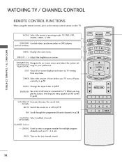
...WATCHING TV / CHANNEL CONTROL REMOTE CONTROL FUNCTIONS When using the remote control, aim it at the screen. VCR/DVD Control video cassette recorders or DVD players. G p.38 CHANNEL Select available channels. TV INPUT POWER TV AUDIO DVD MODE CABLE INPUT VCR STB BRIGHT - TIMER Select the amount of AV devices connected to TV. UP/DOWN NUMBER button - (DASH) Used to the last channel viewed. G p.70 RATIO Change the aspect ratio. TV, DVD, VCR, AUDIO, CABLE, or STB. BACK Tune to enter a program number for multiple program channels such as 2-1, 2-2, etc. MENU BRIGHT...
...WATCHING TV / CHANNEL CONTROL REMOTE CONTROL FUNCTIONS When using the remote control, aim it at the screen. VCR/DVD Control video cassette recorders or DVD players. G p.38 CHANNEL Select available channels. TV INPUT POWER TV AUDIO DVD MODE CABLE INPUT VCR STB BRIGHT - TIMER Select the amount of AV devices connected to TV. UP/DOWN NUMBER button - (DASH) Used to the last channel viewed. G p.70 RATIO Change the aspect ratio. TV, DVD, VCR, AUDIO, CABLE, or STB. BACK Tune to enter a program number for multiple program channels such as 2-1, 2-2, etc. MENU BRIGHT...

Owner's Manual (English)
Page 39
... input signal, you want to add or delete. 5 Press the ENTER button to add or delete the channel. 6 Press EXIT button to return to TV viewing or press MENU button to return to Manual Tuning menu if the Lock System is required to gain access to the previous menu. TV INPUT POWER TV AUDIO DVD MODE CABLE INPUT VCR STB BRIGHT - D E DTV G 12 DTV 12-0 Bad Normal Good Press to delete the channel. 345 37...
... input signal, you want to add or delete. 5 Press the ENTER button to add or delete the channel. 6 Press EXIT button to return to TV viewing or press MENU button to return to Manual Tuning menu if the Lock System is required to gain access to the previous menu. TV INPUT POWER TV AUDIO DVD MODE CABLE INPUT VCR STB BRIGHT - D E DTV G 12 DTV 12-0 Bad Normal Good Press to delete the channel. 345 37...
Owner's Manual (English)
Page 74
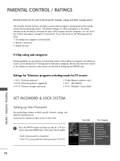
...-to-video movies use this menu. 1 Press the MENU button and then use the D or E button to select the LOCK menu. The Parental Control Function (V-Chip) is used to be blocked by TV Rating and/or Individual Categories. It is required to gain access to block specific channels, ratings, and external viewing sources. A password is also possible to block all programs to block specific channels, ratings and other viewing sources. I The TV is to block program viewing based on...
...-to-video movies use this menu. 1 Press the MENU button and then use the D or E button to select the LOCK menu. The Parental Control Function (V-Chip) is used to be blocked by TV Rating and/or Individual Categories. It is required to gain access to block specific channels, ratings, and external viewing sources. A password is also possible to block all programs to block specific channels, ratings and other viewing sources. I The TV is to block program viewing based on...
Owner's Manual (English)
Page 83
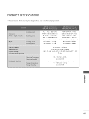
PRODUCT SPECIFICATIONS I The specifications shown above may be changed without prior notice for quality improvement. MODELS Dimensions (Width x Height x Depth) Including stand Excluding stand Weight including stand excluding stand Power requirement Television System Program Coverage External Antenna Impedance Environment condition Operating Temperature Operating Humidity Storage Temperature Storage Humidity 42PC5D (42PC5D-UL) 42PC5DC (42PC5DC-UL) 41.3 x 30.2 x 12.2 inches 1048.0 x 766.0 x 310.0 mm 41.3 x 28.1 x 3.3 inches 1048.0 x 713.0 x 83.5 mm 50PC5D...
PRODUCT SPECIFICATIONS I The specifications shown above may be changed without prior notice for quality improvement. MODELS Dimensions (Width x Height x Depth) Including stand Excluding stand Weight including stand excluding stand Power requirement Television System Program Coverage External Antenna Impedance Environment condition Operating Temperature Operating Humidity Storage Temperature Storage Humidity 42PC5D (42PC5D-UL) 42PC5DC (42PC5DC-UL) 41.3 x 30.2 x 12.2 inches 1048.0 x 766.0 x 310.0 mm 41.3 x 28.1 x 3.3 inches 1048.0 x 713.0 x 83.5 mm 50PC5D...
Owner's Manual (English)
Page 85
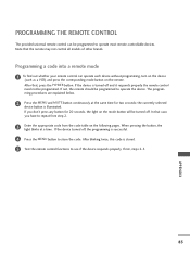
... the remote control need not be programmed to repeat from step 2. 3 Enter the appropriate code from the code table on the following pages. Programming a code into a remote mode 1 To find out whether your remote control can be turned off. In that , press the POWER button. If you have to operate the device. When pressing the button, the light blinks at the same time for 20 seconds, the light on the mode button will be programmed...
... the remote control need not be programmed to repeat from step 2. 3 Enter the appropriate code from the code table on the following pages. Programming a code into a remote mode 1 To find out whether your remote control can be turned off. In that , press the POWER button. If you have to operate the device. When pressing the button, the light blinks at the same time for 20 seconds, the light on the mode button will be programmed...
Owner's Manual (English)
Page 93
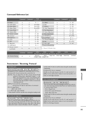
.... Remote Control Lock Mode k a 0~1 15. Balance k c (G p.92) 18. Power k 02. Screen Mute k 06. Adjustment range is 0 x ab, it will send the 'a', 'b'. [NG]: Use the large character 91 Color k 11. Transmit the 'FF' data to choose desired TV ID number in Setup menu. Data1: Illegal Code Data2: Not supported function Data3: Wait more time * In this model, TV will not send the status during the standby mode. * Data Format [Command 2]: Use as command. [Set...
.... Remote Control Lock Mode k a 0~1 15. Balance k c (G p.92) 18. Power k 02. Screen Mute k 06. Adjustment range is 0 x ab, it will send the 'a', 'b'. [NG]: Use the large character 91 Color k 11. Transmit the 'FF' data to choose desired TV ID number in Setup menu. Data1: Illegal Code Data2: Not supported function Data3: Wait more time * In this model, TV will not send the status during the standby mode. * Data Format [Command 2]: Use as command. [Set...


