
User Manual
Page 3
Record model number and serial number of the set . LCD TV OWNER'S MANUAL MODEL: 32LP2DC Internet Home Page : http://www.lgcommercial.com Please read this information to your set . Retain it for future reference. See the label attached on the back cover and quote this manual carefully before operating your dealer when you require service. P/NO : 3828TUL309M (0605-REV00) Printed in Korea
Record model number and serial number of the set . LCD TV OWNER'S MANUAL MODEL: 32LP2DC Internet Home Page : http://www.lgcommercial.com Please read this information to your set . Retain it for future reference. See the label attached on the back cover and quote this manual carefully before operating your dealer when you require service. P/NO : 3828TUL309M (0605-REV00) Printed in Korea
User Manual
Page 6
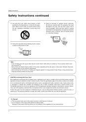
...or cracked wire insulation are dangerous. Periodically examine the cord of your local authority. 4 Pay particular attention to qualified service personnel. Unplug this owner's manual to avoid injury from physical or mechanical abuse, such as power supply cord or plug is required when the apparatus...with an exact replacement part by the manufacturer, or sold with a cart, stand, tripod, bracket, or table specified by an authorized servicer. On Disposal a. Avoid touching the LCD screen or holding your appliance, and if its appearance indicates damage or deterioration, unplug it ...
...or cracked wire insulation are dangerous. Periodically examine the cord of your local authority. 4 Pay particular attention to qualified service personnel. Unplug this owner's manual to avoid injury from physical or mechanical abuse, such as power supply cord or plug is required when the apparatus...with an exact replacement part by the manufacturer, or sold with a cart, stand, tripod, bracket, or table specified by an authorized servicer. On Disposal a. Avoid touching the LCD screen or holding your appliance, and if its appearance indicates damage or deterioration, unplug it ...

User Manual
Page 19
PC INPUT2 DIGITAL AUDIO (OPTICAL) DVI INPUT S-VIDEO (PC/DTV INPUT) R AUDIO L/MONO VIDEO RS-232C INPUT (CONTROL/SERVICE) OUTPUT VIDEO1 COMPONENT1 PC INPUT1 COMPONENT1/DVI R L INPUT AUDIO INPUT VIDEO INPUT 1/2 TV Back 1 Connect one end of an optical cable to... between TV and external equipment. Refer to external audio equipment (stereo system) via the Digital Audio Output Optical port. See the external audio equipment instruction manual for operation. Match the jack colours (Video = yellow, Audio Left = white, and Audio Right = red). 2 Select AV 2 input source with using ...
PC INPUT2 DIGITAL AUDIO (OPTICAL) DVI INPUT S-VIDEO (PC/DTV INPUT) R AUDIO L/MONO VIDEO RS-232C INPUT (CONTROL/SERVICE) OUTPUT VIDEO1 COMPONENT1 PC INPUT1 COMPONENT1/DVI R L INPUT AUDIO INPUT VIDEO INPUT 1/2 TV Back 1 Connect one end of an optical cable to... between TV and external equipment. Refer to external audio equipment (stereo system) via the Digital Audio Output Optical port. See the external audio equipment instruction manual for operation. Match the jack colours (Video = yellow, Audio Left = white, and Audio Right = red). 2 Select AV 2 input source with using ...

User Manual
Page 22
... set-top box to the DIGITAL AUDIO COMPONENT1/DVI INPUT jack on the set. 3 Turn on the digital set-top box. (Refer to the owner's manual for the digital set -top box or other digital external device, refer to COMPONENT2 input (TV side) , select Component 2 input source. (R) AUDIO (L) B...control. - When connecting with a D-sub 15 pin cable AC IN PC AUDIO INPUT2 PC INPUT2 DIGITAL AUDIO (OPTICAL) SPEAKER OUT RS-232C INPUT (CONTROL/SERVICE) OUTPUT PC AUDIO INPUT1 PC INPUT1 COMPONENT1/DVI INPUT TV Back 2 1 Digital Set-top Box (R) AUDIO (L) RGB-DTV OUTPUT When connecting with a ...
... set-top box to the DIGITAL AUDIO COMPONENT1/DVI INPUT jack on the set. 3 Turn on the digital set-top box. (Refer to the owner's manual for the digital set -top box or other digital external device, refer to COMPONENT2 input (TV side) , select Component 2 input source. (R) AUDIO (L) B...control. - When connecting with a D-sub 15 pin cable AC IN PC AUDIO INPUT2 PC INPUT2 DIGITAL AUDIO (OPTICAL) SPEAKER OUT RS-232C INPUT (CONTROL/SERVICE) OUTPUT PC AUDIO INPUT1 PC INPUT1 COMPONENT1/DVI INPUT TV Back 2 1 Digital Set-top Box (R) AUDIO (L) RGB-DTV OUTPUT When connecting with a ...


