
User Manual
Page 1
...that could exceed the limits necessary to your set . Model: Serial: This product qualifies for future reference. LCD TV OWNER'S MANUAL 32LH240H 32LH250H 37LH250H 42LH250H 32LH255H 37LH255H 42LH255H 37LH260H 42LH260H 37LH265H please read this information to quality for ENERGY STAR. 1-800-243-...0000 USA, Consumer User 1-888-865-3026 USA, Commercial User 1-888-542-2623 CANADA LG Customer Information Center P/NO : ...
...that could exceed the limits necessary to your set . Model: Serial: This product qualifies for future reference. LCD TV OWNER'S MANUAL 32LH240H 32LH250H 37LH250H 42LH250H 32LH255H 37LH255H 42LH255H 37LH260H 42LH260H 37LH265H please read this information to quality for ENERGY STAR. 1-800-243-...0000 USA, Consumer User 1-888-865-3026 USA, Commercial User 1-888-542-2623 CANADA LG Customer Information Center P/NO : ...
User Manual
Page 3
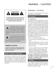
...ELECTRIC SHOCK, DO NOT EXPOSE THIS PRODUCT TO RAIN OR MOISTURE. Consult the dealer or an experienced radio/TV technician for proper grounding and, in the literature accompanying the appliance. These limits are not expressly approved by... could void the user's authority to an outlet on , the user is connected. - NOTE TO CABLE/TV INSTALLER This reminder is intended to alert the user to the presence of the cable entry as close to the...interference by turning the equipment off and on a circuit different from LG Electronics. Reorient or relocate the receiving antenna. -
...ELECTRIC SHOCK, DO NOT EXPOSE THIS PRODUCT TO RAIN OR MOISTURE. Consult the dealer or an experienced radio/TV technician for proper grounding and, in the literature accompanying the appliance. These limits are not expressly approved by... could void the user's authority to an outlet on , the user is connected. - NOTE TO CABLE/TV INSTALLER This reminder is intended to alert the user to the presence of the cable entry as close to the...interference by turning the equipment off and on a circuit different from LG Electronics. Reorient or relocate the receiving antenna. -

User Manual
Page 5
.... Do not try to ground the unit by connecting it , discontinue use a damaged or loose power cord. that appliances be placed upon . Any of the TV. 13 Do not allow an impact shock or any objects to fall into the product, and do not expose this owner's manual to be connected... are dangerous. Be sure do not place objects filled with the power cord plugged in a door, or walked upon a dedicated circuit; Do not touch the TV with something. 14 CAUTION concerning the Power Cord : It is recommend that is the disconnecting device. on the power cord to plugs, wall outlets, and...
.... Do not try to ground the unit by connecting it , discontinue use a damaged or loose power cord. that appliances be placed upon . Any of the TV. 13 Do not allow an impact shock or any objects to fall into the product, and do not expose this owner's manual to be connected... are dangerous. Be sure do not place objects filled with the power cord plugged in a door, or walked upon a dedicated circuit; Do not touch the TV with something. 14 CAUTION concerning the Power Cord : It is recommend that is the disconnecting device. on the power cord to plugs, wall outlets, and...

User Manual
Page 6
...grounding of the lead-in . Do not cover the product with cloth or other odors coming from direct sunlight. 27 For LCD TV If the TV feels cold to the National Electrical Code, ANSI/NFPA 70 Ground Clamp Electric Service Equipment NEC: National Electrical Code Antenna Lead in... more people to grounding electrodes and requirements for a long period, the ventilation openings may occur. Avoid touching the LCD screen or holding your TV where there is installed, follow the precautions below. An outdoor antenna system should not be carried out in the U.S.A. 19 ANTENNAS Outdoor antenna...
...grounding of the lead-in . Do not cover the product with cloth or other odors coming from direct sunlight. 27 For LCD TV If the TV feels cold to the National Electrical Code, ANSI/NFPA 70 Ground Clamp Electric Service Equipment NEC: National Electrical Code Antenna Lead in... more people to grounding electrodes and requirements for a long period, the ventilation openings may occur. Avoid touching the LCD screen or holding your TV where there is installed, follow the precautions below. An outdoor antenna system should not be carried out in the U.S.A. 19 ANTENNAS Outdoor antenna...
User Manual
Page 7
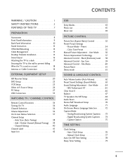
...Manual Clock Setup 77 Auto On/Off Time Setting 78 Sleep Timer Setting 79 5 WARNING / CAUTION 1 SAFETY INSTRUCTIONS 2 FEATURES OF THIS TV 7 PREPARATION Accessories 8 Front Panel Information 9 Back Panel Information 10 Stand Instruction 12 VESA Wall Mounting 14 Cable Management 15 Desktop Pedestal Installation...52 Preset Picture Settings - Color Tone Preset 55 Manual Picture Adjustment - SRS TruSurround XT 65 Clear Voice II 66 Balance 67 TV Speakers On/Off Setup 68 Audio Reset 69 Stereo/SAP Broadcast Setup 70 Audio Language 71 On-Screen Menus Language Selection 72 ...
...Manual Clock Setup 77 Auto On/Off Time Setting 78 Sleep Timer Setting 79 5 WARNING / CAUTION 1 SAFETY INSTRUCTIONS 2 FEATURES OF THIS TV 7 PREPARATION Accessories 8 Front Panel Information 9 Back Panel Information 10 Stand Instruction 12 VESA Wall Mounting 14 Cable Management 15 Desktop Pedestal Installation...52 Preset Picture Settings - Color Tone Preset 55 Manual Picture Adjustment - SRS TruSurround XT 65 Clear Voice II 66 Balance 67 TV Speakers On/Off Setup 68 Audio Reset 69 Stereo/SAP Broadcast Setup 70 Audio Language 71 On-Screen Menus Language Selection 72 ...
User Manual
Page 9
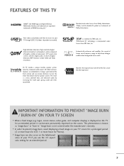
... frequency range to turn the entire front bezel into the speaker system. Manufactured under license from Dolby Laboratories. FEATURES OF THIS TV HDMITM, the HDMI logo and High-Definition Multimedia Interface are trademarks or registered trademarks of digital television, HDTV formats include 1080i and...are trademarks of the film for an extended period. 7 View videos and photos and listen to music on the screen. High-definition television. LG TV include a unique invisible speaker system, tuned by increasing the "sweet spot", giving a wider and richer sound field. "Dolby "and the ...
... frequency range to turn the entire front bezel into the speaker system. Manufactured under license from Dolby Laboratories. FEATURES OF THIS TV HDMITM, the HDMI logo and High-Definition Multimedia Interface are trademarks or registered trademarks of digital television, HDTV formats include 1080i and...are trademarks of the film for an extended period. 7 View videos and photos and listen to music on the screen. High-definition television. LG TV include a unique invisible speaker system, tuned by increasing the "sweet spot", giving a wider and richer sound field. "Dolby "and the ...

User Manual
Page 10
... cores to P.15) 8 If an accessory is not available for Power Cord (This feature is missing, please contact the dealer where you purchased the TV. x 4 x 2 Bolts for stand assembly (Refer to P.12) Torx plus Star head screw (Refer to P.12) Screw for stand fixing (Refer... to P.17) Protection Cover (Refer to P.13) Protective Bracket and Bolt for all models Polishing Cloth * Wipe spots on the exterior only with your TV. Excessive pressure may differ from the images be7lo8 5w6.3 LIST 0 9 VOL MUTE FLASHBK ENTER CH P A G E RETURN 1 4 MARK RATIO POWER 2 INPUT...
... cores to P.15) 8 If an accessory is not available for Power Cord (This feature is missing, please contact the dealer where you purchased the TV. x 4 x 2 Bolts for stand assembly (Refer to P.12) Torx plus Star head screw (Refer to P.12) Screw for stand fixing (Refer... to P.17) Protection Cover (Refer to P.13) Protective Bracket and Bolt for all models Polishing Cloth * Wipe spots on the exterior only with your TV. Excessive pressure may differ from the images be7lo8 5w6.3 LIST 0 9 VOL MUTE FLASHBK ENTER CH P A G E RETURN 1 4 MARK RATIO POWER 2 INPUT...
User Manual
Page 11
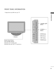
SPEAKER Remote Control Sensor, Power/Standby Indicator Illuminates red in standby mode. PREPARATION FRONT PANEL INFORMATION ■ Image shown may differ from your TV. CH VOL ENTER MENU INPUT CHANNEL (D,E) Buttons VOLUME (+, -) Buttons ENTER Button MENU Button INPUT Button POWER Button 9 Illuminates blue when the TV is switched on.
SPEAKER Remote Control Sensor, Power/Standby Indicator Illuminates red in standby mode. PREPARATION FRONT PANEL INFORMATION ■ Image shown may differ from your TV. CH VOL ENTER MENU INPUT CHANNEL (D,E) Buttons VOLUME (+, -) Buttons ENTER Button MENU Button INPUT Button POWER Button 9 Illuminates blue when the TV is switched on.
User Manual
Page 13
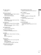
...external speaker input. 6 REMOTE CONTROL OUT IR output for controlling an auxiliary device. 10 RJP (REMOTE JACK PACK PORT) Connect to operate the TV on DC power. 7 UPDATE Enables/disables software downloads and debug mode. Caution: Never attempt to remote jack pack control output port. 11... TV - RESET Performs a hardware reset. 8 RGB IN (PC) Analog PC Connection. Uses a D-sub 15 pin cable (VGA cable). PREPARATION 1 GAME CONTROL Control port 2 AV ...
...external speaker input. 6 REMOTE CONTROL OUT IR output for controlling an auxiliary device. 10 RJP (REMOTE JACK PACK PORT) Connect to operate the TV on DC power. 7 UPDATE Enables/disables software downloads and debug mode. Caution: Never attempt to remote jack pack control output port. 11... TV - RESET Performs a hardware reset. 8 RGB IN (PC) Analog PC Connection. Uses a D-sub 15 pin cable (VGA cable). PREPARATION 1 GAME CONTROL Control port 2 AV ...
User Manual
Page 14
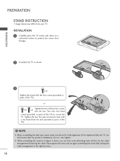
... the noise and try again assembling the stand after the product installation). Tighten the two Torx plus star head screws (provided as parts of the TV). ! or x 2 x 2 Tighten the two of these four screws and the two Torx plus star head screws with the four screws ...bolt is by the cable management disturbing the stand. INSTALLATION 1 Carefully place the TV screen side down on a cushioned surface to secure the TV. PREPARATION PREPARATION STAND INSTRUCTION ■ Image shown may differ from damage. 2 Assemble the TV as shown. 3 x 4 Tighten the stand with a star head driver bit ...
... the noise and try again assembling the stand after the product installation). Tighten the two Torx plus star head screws (provided as parts of the TV). ! or x 2 x 2 Tighten the two of these four screws and the two Torx plus star head screws with the four screws ...bolt is by the cable management disturbing the stand. INSTALLATION 1 Carefully place the TV screen side down on a cushioned surface to secure the TV. PREPARATION PREPARATION STAND INSTRUCTION ■ Image shown may differ from damage. 2 Assemble the TV as shown. 3 x 4 Tighten the stand with a star head driver bit ...
User Manual
Page 15
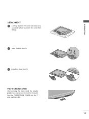
Press the PROTECTION COVER into the TV until you hear it click. 13 PROTECTION COVER After removing the stand, install the included protection cover over the hole for the stand. PREPARATION DETACHMENT 1 Carefully place the TV screen side down on a cushioned surface to protect the screen from damage. 2 Loose the bolts from TV. 3 Detach the stand from TV.
Press the PROTECTION COVER into the TV until you hear it click. 13 PROTECTION COVER After removing the stand, install the included protection cover over the hole for the stand. PREPARATION DETACHMENT 1 Carefully place the TV screen side down on a cushioned surface to protect the screen from damage. 2 Loose the bolts from TV. 3 Detach the stand from TV.
User Manual
Page 16
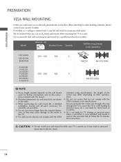
... inside to the floor. CAUTION G Do not install your wall mount kit while your nearest installer. LG is not liable for TV damage or personal injury when a non-VESA or non specified wall mount is not liable for these kinds...TV installation instructions. G For wall mounts that wall mounting be performed by a qualified professional installer. G Standard dimensions for assembly are shown in severe personal injury. It may differ depending on their specifications. Model VESA (A * B) A Standard Screw Quantity B Wall Mounting Bracket (sold separately) 32LH240H, 32LH250H...
... inside to the floor. CAUTION G Do not install your wall mount kit while your nearest installer. LG is not liable for TV damage or personal injury when a non-VESA or non specified wall mount is not liable for these kinds...TV installation instructions. G For wall mounts that wall mounting be performed by a qualified professional installer. G Standard dimensions for assembly are shown in severe personal injury. It may differ depending on their specifications. Model VESA (A * B) A Standard Screw Quantity B Wall Mounting Bracket (sold separately) 32LH240H, 32LH250H...
User Manual
Page 17
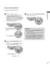
...from being removed by accident. 3 Put the cables inside the CABLE MANAGEMENT CLIP and snap it as shown and bundle the cables. ! If your TV. 1 Connect the cables as shown. To connect additional equipment, see the EXTERNAL EQUIPMENT SETUP section. If these holders are included. It will help ...prevent the power cable from your TV has the CABLE HOLDER, install it closed. NOTE G Do not hold the CABLE MANAGEMENT CLIP when moving the TV. - If the TV is not available for all models.) Or PLUG IN TYPE HOLDER 2 Install the ...
...from being removed by accident. 3 Put the cables inside the CABLE MANAGEMENT CLIP and snap it as shown and bundle the cables. ! If your TV. 1 Connect the cables as shown. To connect additional equipment, see the EXTERNAL EQUIPMENT SETUP section. If these holders are included. It will help ...prevent the power cable from your TV has the CABLE HOLDER, install it closed. NOTE G Do not hold the CABLE MANAGEMENT CLIP when moving the TV. - If the TV is not available for all models.) Or PLUG IN TYPE HOLDER 2 Install the ...
User Manual
Page 18
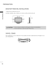
PREPARATION PREPARATION DESKTOP PEDESTAL INSTALLATION ■ Image shown may differ from the wall. 4 inches 4 inches 4 inches 4 inches CAUTION G Ensure adequate ventilation by 90 degrees to the left or right direction by following the clearance recommendations. G Do not mount near or above any type of 4 inches on all four sides from your viewing position. 16 For proper ventilation, allow a clearance of heat source. SWIVEL STAND After installing the TV, you can adjust the TV set manually to suit your TV.
PREPARATION PREPARATION DESKTOP PEDESTAL INSTALLATION ■ Image shown may differ from the wall. 4 inches 4 inches 4 inches 4 inches CAUTION G Ensure adequate ventilation by 90 degrees to the left or right direction by following the clearance recommendations. G Do not mount near or above any type of 4 inches on all four sides from your viewing position. 16 For proper ventilation, allow a clearance of heat source. SWIVEL STAND After installing the TV, you can adjust the TV set manually to suit your TV.
User Manual
Page 19
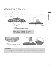
The TV must be attached to a desk so it cannot be securely attached to the floor/wall per installation instructions. Stand Desk 4-Screws (not provided as parts ...) ex) Table depth: 15mm, Screw: M5 x 25 Stand 1-Screw (provided as parts of the product) Desk WARNING G To prevent TV from your TV. Tipping, shaking, or rocking the machine may differ from falling over, the TV should be pulled in a forward/backward direction, potentially causing injury or damaging the product. PREPARATION ATTACHING THE...
The TV must be attached to a desk so it cannot be securely attached to the floor/wall per installation instructions. Stand Desk 4-Screws (not provided as parts ...) ex) Table depth: 15mm, Screw: M5 x 25 Stand 1-Screw (provided as parts of the product) Desk WARNING G To prevent TV from your TV. Tipping, shaking, or rocking the machine may differ from falling over, the TV should be pulled in a forward/backward direction, potentially causing injury or damaging the product. PREPARATION ATTACHING THE...

User Manual
Page 20
... a platform or cabinet strong enough and large enough to support the size and weight of the bracket on the wall and the one on the TV are tightened securely. ■ Use a sturdy rope (sold separately) to the holes in a forward direction, potentially causing injury or damaging the product. Match the height... safer to tie the rope so it cannot fall over (when not using a wall mount). ■ Image shown may differ from the TV. ■ Insert the eye-bolts (or TV brackets and bolts) to tighten the product to a wall so it cannot be pulled in the product. It is mounted on or...
... a platform or cabinet strong enough and large enough to support the size and weight of the bracket on the wall and the one on the TV are tightened securely. ■ Use a sturdy rope (sold separately) to the holes in a forward direction, potentially causing injury or damaging the product. Match the height... safer to tie the rope so it cannot fall over (when not using a wall mount). ■ Image shown may differ from the TV. ■ Insert the eye-bolts (or TV brackets and bolts) to tighten the product to a wall so it cannot be pulled in the product. It is mounted on or...

User Manual
Page 21
...quality in a poor signal area, please purchase a signal amplifier and install properly. ■ If the antenna needs to be split for two TV's, install a 2-Way Signal Splitter. ■ If the antenna is not installed properly, contact your dealer for outdoor antenna) Copper Wire Be ...all connections are made between the devices. Antenna (Analog or Digital) Wall Antenna Socket or Outdoor Antenna without a Cable Box Connection. Cable Cable TV Wall Jack RF Coaxial Wire (75 ohm) ANTENNA IN M.P.I . ANTENNA OR CABLE CONNECTION 1. PREPARATION ■ To prevent damage do not connect...
...quality in a poor signal area, please purchase a signal amplifier and install properly. ■ If the antenna needs to be split for two TV's, install a 2-Way Signal Splitter. ■ If the antenna is not installed properly, contact your dealer for outdoor antenna) Copper Wire Be ...all connections are made between the devices. Antenna (Analog or Digital) Wall Antenna Socket or Outdoor Antenna without a Cable Box Connection. Cable Cable TV Wall Jack RF Coaxial Wire (75 ohm) ANTENNA IN M.P.I . ANTENNA OR CABLE CONNECTION 1. PREPARATION ■ To prevent damage do not connect...

User Manual
Page 22
... equipment. ■ Image shown may differ from a digital set-top box or other digital external device, refer to the COMPONENT IN AUDIO jacks on the TV. 2. How to connect 1 Connect the video outputs (Y, PB, PR) of the digital set-top box to the figure as shown below. Component Connection 1. ...Match the jack colors (Y = green, PB = blue, and PR = red). HD RECEIVER SETUP This TV can receive Digital Over-the-air or Digital Cable signals without an external digital set-top box. How to use ■ Turn on the digital...
... equipment. ■ Image shown may differ from a digital set-top box or other digital external device, refer to the COMPONENT IN AUDIO jacks on the TV. 2. How to connect 1 Connect the video outputs (Y, PB, PR) of the digital set-top box to the figure as shown below. Component Connection 1. ...Match the jack colors (Y = green, PB = blue, and PR = red). HD RECEIVER SETUP This TV can receive Digital Over-the-air or Digital Cable signals without an external digital set-top box. How to use ■ Turn on the digital...
User Manual
Page 23
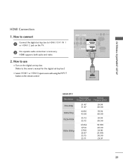
... set -top box to connect 1 Connect the digital set -top box.) ■ Select HDMI1 or HDMI2 input source with using the INPUT button on the TV. 2 No separate audio connection is necessary. How to HDMI /DVI IN 1 or HDMI 2 jack on the remote control.
... set -top box to connect 1 Connect the digital set -top box.) ■ Select HDMI1 or HDMI2 input source with using the INPUT button on the TV. 2 No separate audio connection is necessary. How to HDMI /DVI IN 1 or HDMI 2 jack on the remote control.

User Manual
Page 24
... RS-232C IN (SERVICE ONLY) SPEAKER OUT REMOTE (8 ) CONTROL OUT 1 2 ! EXTERNAL EQUIPMENT SETUP EXTERNAL EQUIPMENT SETUP DVI to the HDMI/DVI IN 1 jack on the TV. 2 Connect the audio output of the digital set -top box.) ■ Select the HDMI1 input source on the...
... RS-232C IN (SERVICE ONLY) SPEAKER OUT REMOTE (8 ) CONTROL OUT 1 2 ! EXTERNAL EQUIPMENT SETUP EXTERNAL EQUIPMENT SETUP DVI to the HDMI/DVI IN 1 jack on the TV. 2 Connect the audio output of the digital set -top box.) ■ Select the HDMI1 input source on the...


