User Manual
Page 6
... 20 DVD Setup 23 VCR Setup 25 Other A/V Source Setup 27 USB Connection 28 Audio out Connection 29 PC Setup 30 WATCHING TV / CHANNEL CONTROL Remote Control Functions 36 Turning On TV 38 Channel Selection 38 Volume Adjustment 38 Initial Setting 39 On-Screen Menus Selection 40 Quick Menu 41 6 Channel...
... 20 DVD Setup 23 VCR Setup 25 Other A/V Source Setup 27 USB Connection 28 Audio out Connection 29 PC Setup 30 WATCHING TV / CHANNEL CONTROL Remote Control Functions 36 Turning On TV 38 Channel Selection 38 Volume Adjustment 38 Initial Setting 39 On-Screen Menus Selection 40 Quick Menu 41 6 Channel...
User Manual
Page 9
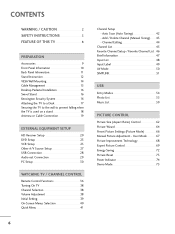
...POWER 2 ENERGYINSAPVUINGT 753 86 LIST 0 9 VOL MUTE FLASHBK MENU Q.MENU ENTER RETURN FAMVARK CH P A G E 1.5V 1.5V (For 26LH210C, 32LH210C) MUTE SAP INFO CC POWER 1 4 7 5 8 TIMER 0 INPUT 9 FLASHBK RETURN VOL CH OK CH VOL 2 3 6 BED1 BED2 1.5V 1.5V Owner's Manual... CD Manual Installer Remote Control, User Remote Control, Batteries Batteries Power Cord (Except 47LH300C) x 4 Screws for stand assembly Screw for stand fixing (Refer to P.12) (Refer ...
...POWER 2 ENERGYINSAPVUINGT 753 86 LIST 0 9 VOL MUTE FLASHBK MENU Q.MENU ENTER RETURN FAMVARK CH P A G E 1.5V 1.5V (For 26LH210C, 32LH210C) MUTE SAP INFO CC POWER 1 4 7 5 8 TIMER 0 INPUT 9 FLASHBK RETURN VOL CH OK CH VOL 2 3 6 BED1 BED2 1.5V 1.5V Owner's Manual... CD Manual Installer Remote Control, User Remote Control, Batteries Batteries Power Cord (Except 47LH300C) x 4 Screws for stand assembly Screw for stand fixing (Refer to P.12) (Refer ...
User Manual
Page 10
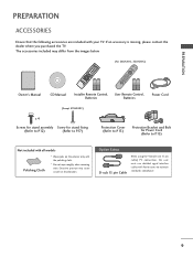
... shown may differ from your TV. 26LH200C, 26LH210C INPUT Button POWER Button MENU Button ENTER Button VOLUME CHANNEL (-, +) Buttons (E,D) Buttons INPUT MENU ENTER VOL CH 32LH210C, 32/37/42LH200C, 42/47LH300C SPEAKER Remote Control Sensor, Power/Standby Indicator Illuminates red in the OPTION menu.
... shown may differ from your TV. 26LH200C, 26LH210C INPUT Button POWER Button MENU Button ENTER Button VOLUME CHANNEL (-, +) Buttons (E,D) Buttons INPUT MENU ENTER VOL CH 32LH210C, 32/37/42LH200C, 42/47LH300C SPEAKER Remote Control Sensor, Power/Standby Indicator Illuminates red in the OPTION menu.
User Manual
Page 11
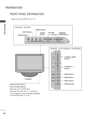
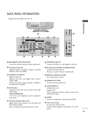
...for external speaker jack. 10 COMPONENT IN Analog Connection. Accepts DVI video using an adapter or HDMI to this port doesn't work. 8 REMOTE CONTROL IN PORT For a wired remote control. 9 SPEAKER OUT PORT Used for Service or Hotel mode. 3 HDMI/DVI IN, HDMI IN Digital Connection. PREPARATION USB IN 12...IN 1 VIDEO AUDIO 2 L(MONO) R 1 VIDEO COMPONENT IN L AUDIO R L R SPEAKER OUT 3 4 5 RGB IN (PC) AUDIO IN /DVI IN (RGB/DVI) OPTICAL DIGITAL AUDIO OUT REMOTE ANTENNA/ RS-232C IN CABLE IN CONTROL IN (CONTROL&SERVICE) 10 9 8 7 6 VIDEO L/MONO AUDIO R R 11 2 AV IN 2 1 RJP...
...for external speaker jack. 10 COMPONENT IN Analog Connection. Accepts DVI video using an adapter or HDMI to this port doesn't work. 8 REMOTE CONTROL IN PORT For a wired remote control. 9 SPEAKER OUT PORT Used for Service or Hotel mode. 3 HDMI/DVI IN, HDMI IN Digital Connection. PREPARATION USB IN 12...IN 1 VIDEO AUDIO 2 L(MONO) R 1 VIDEO COMPONENT IN L AUDIO R L R SPEAKER OUT 3 4 5 RGB IN (PC) AUDIO IN /DVI IN (RGB/DVI) OPTICAL DIGITAL AUDIO OUT REMOTE ANTENNA/ RS-232C IN CABLE IN CONTROL IN (CONTROL&SERVICE) 10 9 8 7 6 VIDEO L/MONO AUDIO R R 11 2 AV IN 2 1 RJP...
User Manual
Page 20
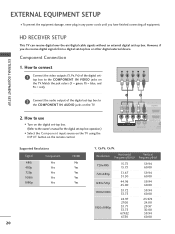
... (Y = green, PB = blue, and PR = red). How to use I Turn on the digital set-top box. (Refer to the COMPONENT IN VIDEO jacks on the remote control. 1 2 RJP AV IN 1 VIDEO AUDIO 2 L(MONO) R 1 VIDEO COMPONENT IN L AUDIO R L R SPEAKER OUT /DVI IN REMO CONTRO Supported Resolutions Signal Component 480i Yes 480p Yes...
... (Y = green, PB = blue, and PR = red). How to use I Turn on the digital set-top box. (Refer to the COMPONENT IN VIDEO jacks on the remote control. 1 2 RJP AV IN 1 VIDEO AUDIO 2 L(MONO) R 1 VIDEO COMPONENT IN L AUDIO R L R SPEAKER OUT /DVI IN REMO CONTRO Supported Resolutions Signal Component 480i Yes 480p Yes...
User Manual
Page 21
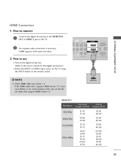
...that support HDMI version 1.3. P AV IN 1 VIDEO AUDIO 2 L(MONO) R 1 DEO ONENT IN L AUDIO R L R SPEAKER OUT RGB IN (PC) AUDIO IN O /DVI IN (RGB/DVI) REMOTE RS-232C IN CONTROL IN (CONTROL&SERVICE) 1 HDMI OUTPUT HDMI-DTV Resolution Horizontal Vertical Frequency(KHz) Frequency(Hz) 720x480p 1280x720p 1920x1080i 1920x1080p 31.47 31...(Refer to the owner's manual for the digital set -top box to connect 1 Connect the digital set -top box.) I N 1or HDMI 2 jack on the remote control. ! HDMI supports both audio and video. 2. NOTE G Check HDMI cable over version 1.3.
...that support HDMI version 1.3. P AV IN 1 VIDEO AUDIO 2 L(MONO) R 1 DEO ONENT IN L AUDIO R L R SPEAKER OUT RGB IN (PC) AUDIO IN O /DVI IN (RGB/DVI) REMOTE RS-232C IN CONTROL IN (CONTROL&SERVICE) 1 HDMI OUTPUT HDMI-DTV Resolution Horizontal Vertical Frequency(KHz) Frequency(Hz) 720x480p 1280x720p 1920x1080i 1920x1080p 31.47 31...(Refer to the owner's manual for the digital set -top box to connect 1 Connect the digital set -top box.) I N 1or HDMI 2 jack on the remote control. ! HDMI supports both audio and video. 2. NOTE G Check HDMI cable over version 1.3.
User Manual
Page 22
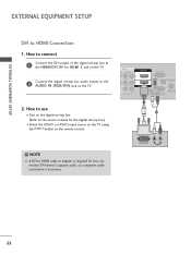
... owner's manual for this connection. AV IN 1 O AUDIO 2 L(MONO) R 1 L AUDIO R L R SPEAKER OUT RGB IN (PC) AUDIO IN /DVI IN (RGB/DVI) OPTICAL DIGIT AUDIO OUT REMOTE RS-232C IN ACNATBELNENIAN CONTROL IN (CONTROL&SERVICE) 1 2 ! DVI OUTPUT L R AUDIO 22 How to connect 1 Connect the DVI output of the digital set-top box... (RGB/DVI) jack on the TV. 2. How to use I Select the HDMI1 or HDMI2 input source on the TV using the INPUT button on the remote control.
... owner's manual for this connection. AV IN 1 O AUDIO 2 L(MONO) R 1 L AUDIO R L R SPEAKER OUT RGB IN (PC) AUDIO IN /DVI IN (RGB/DVI) OPTICAL DIGIT AUDIO OUT REMOTE RS-232C IN ACNATBELNENIAN CONTROL IN (CONTROL&SERVICE) 1 2 ! DVI OUTPUT L R AUDIO 22 How to connect 1 Connect the DVI output of the digital set-top box... (RGB/DVI) jack on the TV. 2. How to use I Select the HDMI1 or HDMI2 input source on the TV using the INPUT button on the remote control.
User Manual
Page 23
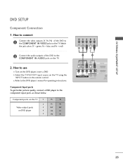
... Cr Pb Pr Y PB PR L R 1 2 RJP AV IN 1 VIDEO AUDIO 2 L(MONO) R 1 VIDEO COMPONENT IN L AUDIO R L R SPEAKER OUT /DVI IN REMOT CONTRO 23 Component ports on the TV Y Y Video output ports Y on the remote control. Component Input ports To get better picture quality, connect a DVD player to the DVD player's manual for operating...
... Cr Pb Pr Y PB PR L R 1 2 RJP AV IN 1 VIDEO AUDIO 2 L(MONO) R 1 VIDEO COMPONENT IN L AUDIO R L R SPEAKER OUT /DVI IN REMOT CONTRO 23 Component ports on the TV Y Y Video output ports Y on the remote control. Component Input ports To get better picture quality, connect a DVD player to the DVD player's manual for operating...
User Manual
Page 24
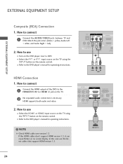
...DVD. HDMI supports both audio and video. 2. RJP AV IN 1 VIDEO AUDIO 2 L(MONO) R 1 VIDEO COMPONENT IN L AUDIO R L R SPEAKER OUT 1 /DVI IN REMOTE CONTROL VIDEO L R AUDIO AV IN 1 VIDEO AUDIO 2 L(MONO) R 1 L AUDIO R IN L R SPEAKER OUT RGB IN (PC) AUDIO IN /DVI IN (RGB/DVI) OPTICAL...output of the DVD to use the latest cables that support HDMI version 1.3. How to the HDMI/DVI IN 1or HDMI 2 jack on the remote control. HDMI OUTPUT 24 EXTERNAL EQUIPMENT SETUP EXTERNAL EQUIPMENT SETUP Composite (RCA) Connection 1. Match the jack colors (Video = yellow, Audio Left ...
...DVD. HDMI supports both audio and video. 2. RJP AV IN 1 VIDEO AUDIO 2 L(MONO) R 1 VIDEO COMPONENT IN L AUDIO R L R SPEAKER OUT 1 /DVI IN REMOTE CONTROL VIDEO L R AUDIO AV IN 1 VIDEO AUDIO 2 L(MONO) R 1 L AUDIO R IN L R SPEAKER OUT RGB IN (PC) AUDIO IN /DVI IN (RGB/DVI) OPTICAL...output of the DVD to use the latest cables that support HDMI version 1.3. How to the HDMI/DVI IN 1or HDMI 2 jack on the remote control. HDMI OUTPUT 24 EXTERNAL EQUIPMENT SETUP EXTERNAL EQUIPMENT SETUP Composite (RCA) Connection 1. Match the jack colors (Video = yellow, Audio Left ...
User Manual
Page 26
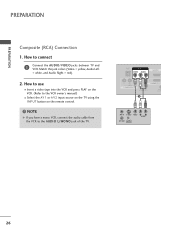
... jack colors (Video = yellow, Audio Left = white, and Audio Right = red). 2. How to use I Insert a video tape into the VCR and press PLAY on the remote control. ! How to connect 1 Connect the AUDIO/VIDEO jacks between TV and VCR.
... jack colors (Video = yellow, Audio Left = white, and Audio Right = red). 2. How to use I Insert a video tape into the VCR and press PLAY on the remote control. ! How to connect 1 Connect the AUDIO/VIDEO jacks between TV and VCR.
User Manual
Page 27
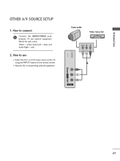
How to connect 1 Connect the AUDIO/VIDEO jacks between TV and external equipment. Match the jack colors. (Video = yellow, Audio Left = white, and Audio Right = red) 2. USB IN Camcorder Video Game Set VIDEO L R 1 VIDEO L/MONO AUDIO R AV IN 2 27 I Select the A V 1 or A V 2 input source on the TV using the INPUT button on the remote control. How to use I Operate the corresponding external equipment. PREPARATION OTHER A/V SOURCE SETUP 1.
How to connect 1 Connect the AUDIO/VIDEO jacks between TV and external equipment. Match the jack colors. (Video = yellow, Audio Left = white, and Audio Right = red) 2. USB IN Camcorder Video Game Set VIDEO L R 1 VIDEO L/MONO AUDIO R AV IN 2 27 I Select the A V 1 or A V 2 input source on the TV using the INPUT button on the remote control. How to use I Operate the corresponding external equipment. PREPARATION OTHER A/V SOURCE SETUP 1.

User Manual
Page 29
.... (G p.82) 1 RJP AV IN 1 VIDEO AUDIO 2 L(MONO) R 1 VIDEO COMPONENT IN L AUDIO R L R SPEAKER OUT AU (RG /DVI IN REMOTE CONTROL IN (C O 2 R 1 R R OUT RGB IN (PC) AUDIO IN OPTICAL DIGITAL AUDIO OUT /DVI IN (RGB/DVI) 1 REMOTE ANTENNA/ RS-232C IN CABLE IN CONTROL IN (CONTROL&SERVICE) 2 CAUTION G Do not look into the optical...
.... (G p.82) 1 RJP AV IN 1 VIDEO AUDIO 2 L(MONO) R 1 VIDEO COMPONENT IN L AUDIO R L R SPEAKER OUT AU (RG /DVI IN REMOTE CONTROL IN (C O 2 R 1 R R OUT RGB IN (PC) AUDIO IN OPTICAL DIGITAL AUDIO OUT /DVI IN (RGB/DVI) 1 REMOTE ANTENNA/ RS-232C IN CABLE IN CONTROL IN (CONTROL&SERVICE) 2 CAUTION G Do not look into the optical...
User Manual
Page 30
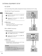
...use I Select the HDMI1 or HDMI2 input source on the TV using the INPUT button on the remote control. 2 1 DVI to HDMI Connection 1. If the HDMI cables don't support HDMI version 1.3, ...ENT IN L AUDIO R L R SPEAKER OUT RGB IN (PC) AUDIO IN /DVI IN (RGB/DVI) OPTI AU A REMOTE RS-232C IN C CONTROL IN (CONTROL&SERVICE) 1 2 DVI OUTPUT AUDIO How to connect 1 Connect the VGA output of the...to use the latest cables that the PC adjusts automatically to the AUDIO IN (RGB/DVI) jack on the remote control. ! In this case use I N 1or HDMI 2 jack on the TV. 2 Connect the PC...
...use I Select the HDMI1 or HDMI2 input source on the TV using the INPUT button on the remote control. 2 1 DVI to HDMI Connection 1. If the HDMI cables don't support HDMI version 1.3, ...ENT IN L AUDIO R L R SPEAKER OUT RGB IN (PC) AUDIO IN /DVI IN (RGB/DVI) OPTI AU A REMOTE RS-232C IN C CONTROL IN (CONTROL&SERVICE) 1 2 DVI OUTPUT AUDIO How to connect 1 Connect the VGA output of the...to use the latest cables that the PC adjusts automatically to the AUDIO IN (RGB/DVI) jack on the remote control. ! In this case use I N 1or HDMI 2 jack on the TV. 2 Connect the PC...
User Manual
Page 36
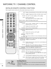
... the system (Up/Down/Left Right/ENTER) settings to the last channel viewed. When you toggle this button, the SIMPLINK menu appears at the remote control sensor on from standby. G p.46 MARK Select the input to TV viewing. G p.50 POWER Turns the TV on the TV. Also...Displays the main menu or clears all on from standby or off . WATCHING TV / CHANNEL CONTROL WATCHING TV / CHANNEL CONTROL INSTALLER REMOTE CONTROL FUNCTIONS When using the remote control, aim it at the screen. UP/DOWN PAGE Moves from one step in an interactive application or other user interaction function. ...
... the system (Up/Down/Left Right/ENTER) settings to the last channel viewed. When you toggle this button, the SIMPLINK menu appears at the remote control sensor on from standby. G p.46 MARK Select the input to TV viewing. G p.50 POWER Turns the TV on the TV. Also...Displays the main menu or clears all on from standby or off . WATCHING TV / CHANNEL CONTROL WATCHING TV / CHANNEL CONTROL INSTALLER REMOTE CONTROL FUNCTIONS When using the remote control, aim it at the screen. UP/DOWN PAGE Moves from one step in an interactive application or other user interaction function. ...
User Manual
Page 37
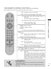
... aim it to the Bed 1/Bed 2 position. G p.38 POWER Turns the TV on the TV. I Install two 1.5V AAA batteries. USER REMOTE CONTROL FUNCTIONS (For 26/32LH210C) When using a paper clip or a ball point pen to slide switch to move return one step in the Installation menu. WATCHING TV / CHANNEL ...menus and adjusts the system (Up/Down/Left Right) settings to the setting in an interactive application or other user interaction function. On the patient's remote, the Bed 1/Bed 2 position can be selected by sliding it at the top of the Bed 1/Bed 2 switch must correspond to your TV ...
... aim it to the Bed 1/Bed 2 position. G p.38 POWER Turns the TV on the TV. I Install two 1.5V AAA batteries. USER REMOTE CONTROL FUNCTIONS (For 26/32LH210C) When using a paper clip or a ball point pen to slide switch to move return one step in the Installation menu. WATCHING TV / CHANNEL ...menus and adjusts the system (Up/Down/Left Right) settings to the setting in an interactive application or other user interaction function. On the patient's remote, the Bed 1/Bed 2 position can be selected by sliding it at the top of the Bed 1/Bed 2 switch must correspond to your TV ...
User Manual
Page 38
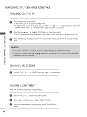
... state it will appear whenever the TV is switched on until the Initial setting procedure is out. 3 When finished using the INPUT button on the remote control. 2 Select the viewing source by pressing the MUTE or VOL (+ or -) button. 38 NOTE G If you want to turn TV on, press the , ...INPUT, CH (DE or ) button on the TV or press the POWER, INPUT, CH ( or ), Number (0~9) button on the remote control. VOLUME ADJUSTMENT Adjust the volume to suit your personal preference. 1 Press the VOL (+ or -) button to adjust the volume. 2 If you intend to standby...
... state it will appear whenever the TV is switched on until the Initial setting procedure is out. 3 When finished using the INPUT button on the remote control. 2 Select the viewing source by pressing the MUTE or VOL (+ or -) button. 38 NOTE G If you want to turn TV on, press the , ...INPUT, CH (DE or ) button on the TV or press the POWER, INPUT, CH ( or ), Number (0~9) button on the remote control. VOLUME ADJUSTMENT Adjust the volume to suit your personal preference. 1 Press the VOL (+ or -) button to adjust the volume. 2 If you intend to standby...
User Manual
Page 51
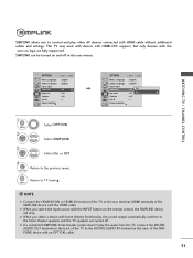
... Indicator E 1 MENU 2 ENTER Select OPTION. NOTE G Connect the HDMI/DVI IN or HDMI IN terminal of the SIMPLINK device with the INPUT button on the remote control, the SIMPLINK device will stop. G If a connected SIMPLINK home theater system doesn't play other AV devices connected with the logo are turned off in...
... Indicator E 1 MENU 2 ENTER Select OPTION. NOTE G Connect the HDMI/DVI IN or HDMI IN terminal of the SIMPLINK device with the INPUT button on the remote control, the SIMPLINK device will stop. G If a connected SIMPLINK home theater system doesn't play other AV devices connected with the logo are turned off in...
User Manual
Page 55
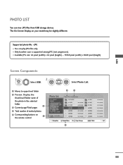
The On-Screen Display on 1 the remote control 3 4 Photo List Drive1 JMJ001 1366x768, 125KB Up Folder Page 2/3 No Marked Up Folder KY101 06/10/2008 KY102 04/03/2008 JMJ001 01/01/...
The On-Screen Display on 1 the remote control 3 4 Photo List Drive1 JMJ001 1366x768, 125KB Up Folder Page 2/3 No Marked Up Folder KY101 06/10/2008 KY102 04/03/2008 JMJ001 01/01/...
User Manual
Page 59
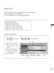
..., 11.025 kHz, 12 kHz Screen Components 1 MENU Select U S B. 2 ENTER ENTER Select M u s i c L i s t. 1 Moves to play back copy-protected files. The On Screen Display on 5 the remote control. 1 Music List Drive1 3 4 Page 2/3 No Marked Title Up Folder A 00:00 / 04:16 Up Folder Navigation Popup Menu CH Page Change 5 Duration MARK Mark...
..., 11.025 kHz, 12 kHz Screen Components 1 MENU Select U S B. 2 ENTER ENTER Select M u s i c L i s t. 1 Moves to play back copy-protected files. The On Screen Display on 5 the remote control. 1 Music List Drive1 3 4 Page 2/3 No Marked Title Up Folder A 00:00 / 04:16 Up Folder Navigation Popup Menu CH Page Change 5 Duration MARK Mark...
User Manual
Page 103
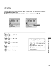
MENU I In Key Lock 'O n', if the TV is turned off . Key Lock' appears on the screen if any button on the remote control. OPTION Move Enter Menu Language Audio Language Input Label SIMPLINK Key Lock Caption Set ID Power Indicator E : English : English : On : Off : Off : 1 OPTION Move ... locking out the front panel controls, so that it was last set to TV viewing. KEY LOCK This feature can only be used with the remote control.
MENU I In Key Lock 'O n', if the TV is turned off . Key Lock' appears on the screen if any button on the remote control. OPTION Move Enter Menu Language Audio Language Input Label SIMPLINK Key Lock Caption Set ID Power Indicator E : English : English : On : Off : Off : 1 OPTION Move ... locking out the front panel controls, so that it was last set to TV viewing. KEY LOCK This feature can only be used with the remote control.


