
User Manual
Page 3
... the limits for help. WARNING / CAUTION TO REDUCE THE RISK OF ELECTRIC SHOCK DO NOT REMOVE COVER (OR BACK). NO USER SERVICEABLE PARTS INSIDE. FCC NOTICE Class B digital device This equipment has been tested and found to comply with the instructions, may be connected to the grounding system of electric shock to operate the equipment. Reorient or relocate the receiving antenna. -
... the limits for help. WARNING / CAUTION TO REDUCE THE RISK OF ELECTRIC SHOCK DO NOT REMOVE COVER (OR BACK). NO USER SERVICEABLE PARTS INSIDE. FCC NOTICE Class B digital device This equipment has been tested and found to comply with the instructions, may be connected to the grounding system of electric shock to operate the equipment. Reorient or relocate the receiving antenna. -

User Manual
Page 5
... exact replacement part by connecting it , discontinue use a damaged or loose power cord. Do not try to ground the unit by an authorized servicer. that is the disconnecting device. Any of the appliance, and have a qualified electrician install a separate circuit breaker. Periodically examine the cord of your appliance, and if its appearance indicates damage or deterioration, unplug it to plugs, wall...
... exact replacement part by connecting it , discontinue use a damaged or loose power cord. Do not try to ground the unit by an authorized servicer. that is the disconnecting device. Any of the appliance, and have a qualified electrician install a separate circuit breaker. Periodically examine the cord of your appliance, and if its appearance indicates damage or deterioration, unplug it to plugs, wall...

User Manual
Page 6
... Clamps Power Service Grounding Electrode System (NEC Art 250, Part H) 21 Cleaning When cleaning, unplug the power cord and scrub gently with chemicals such as death or serious injury can occur. Do not clean with a soft cloth to carry larger TVs. 20 ANTENNAS Outdoor antenna grounding If an outdoor antenna is turned off, unplugged and all cables have been removed. Do...
... Clamps Power Service Grounding Electrode System (NEC Art 250, Part H) 21 Cleaning When cleaning, unplug the power cord and scrub gently with chemicals such as death or serious injury can occur. Do not clean with a soft cloth to carry larger TVs. 20 ANTENNAS Outdoor antenna grounding If an outdoor antenna is turned off, unplugged and all cables have been removed. Do...

User Manual
Page 7
...40 Input List 41 PICTURE CONTROL Picture Size (Aspect Ratio) Control 42 Preset Picture Settings - Real Cinema 51 Picture Reset 52 SOUND & LANGUAGE CONTROL Auto Volume Leveler (Auto Volume 53 Clear Voice 54 Preset Sound Settings (Sound Mode 55 Sound Setting Adjustment - Picture Mode - Black (Darkness) Level 50 Advanced Control - Auto Clock Setup 67 Manual Clock Setup 68 Auto On/Off Time Setting 69 Sleep Timer Setting 70 Auto Shut-off Setting 71 PARENTAL CONTROL / RATINGS Set Password & Lock System 72 Channel Blocking 75 Movie & TV Rating 76 Downloadable Rating...
...40 Input List 41 PICTURE CONTROL Picture Size (Aspect Ratio) Control 42 Preset Picture Settings - Real Cinema 51 Picture Reset 52 SOUND & LANGUAGE CONTROL Auto Volume Leveler (Auto Volume 53 Clear Voice 54 Preset Sound Settings (Sound Mode 55 Sound Setting Adjustment - Picture Mode - Black (Darkness) Level 50 Advanced Control - Auto Clock Setup 67 Manual Clock Setup 68 Auto On/Off Time Setting 69 Sleep Timer Setting 70 Auto Shut-off Setting 71 PARENTAL CONTROL / RATINGS Set Password & Lock System 72 Channel Blocking 75 Movie & TV Rating 76 Downloadable Rating...

User Manual
Page 9
CD Manual 22LG3DCH only Cable Management Clip (Refer to P.12) Power Cord Protective Bracket and Bolt for Power Cord (Refer to P.12) (This feature is not available for all models.) discoloration. 32LG3DC only PICTURE TV SOUND POWER 1 4 2 SAP INPUT RATIO 7 5 3 - 8 6 0 9 ADJUST ENTER VOL TIMER CC MUTE MENU CH RETURN FLASHBK 1.5V 1.5V Remote Control, Batteries x 4 x 4 M4xL26 Ø4xL20 (Machine Screw) (Plastic Screw) Bolts for stand assembly (Refer to P.11) x 2 M4xL22 (Machine Screw) Torx plus Star...
CD Manual 22LG3DCH only Cable Management Clip (Refer to P.12) Power Cord Protective Bracket and Bolt for Power Cord (Refer to P.12) (This feature is not available for all models.) discoloration. 32LG3DC only PICTURE TV SOUND POWER 1 4 2 SAP INPUT RATIO 7 5 3 - 8 6 0 9 ADJUST ENTER VOL TIMER CC MUTE MENU CH RETURN FLASHBK 1.5V 1.5V Remote Control, Batteries x 4 x 4 M4xL26 Ø4xL20 (Machine Screw) (Plastic Screw) Bolts for stand assembly (Refer to P.11) x 2 M4xL22 (Machine Screw) Torx plus Star...

User Manual
Page 12
.... Uses a red, green, and blue cable for video & a red and white cable for audio. 8 AUDIO IN (RGB/DVI) (Except 22LG3DCH model) 1/8" headphone jack for analog PC audio input. 9 REMOTE CONTROL OUT IR output for PC/DTV audio input jack (Only 22LG3DCHUA model). Accepts DVI video using an adapter or HDMI to this jack. 14 M.P. Caution: Never attempt to operate the TV on DC power. 13 ANTENNA IN Connect over-the air signals to DVI cable (not included). 3 USB IN SERVICE ONLY Used for software updates...
.... Uses a red, green, and blue cable for video & a red and white cable for audio. 8 AUDIO IN (RGB/DVI) (Except 22LG3DCH model) 1/8" headphone jack for analog PC audio input. 9 REMOTE CONTROL OUT IR output for PC/DTV audio input jack (Only 22LG3DCHUA model). Accepts DVI video using an adapter or HDMI to this jack. 14 M.P. Caution: Never attempt to operate the TV on DC power. 13 ANTENNA IN Connect over-the air signals to DVI cable (not included). 3 USB IN SERVICE ONLY Used for software updates...

User Manual
Page 19
... or Digital Cable signals without an external digital set -top box to the COMPONENT IN AUDIO jacks on the TV. 1 HDMI/DVI IN UPDATE 2 RESET USB IN SERVUCE ONLY RS-232C IN (SERVICE ONLY) 2. EXTERNAL EQUIPMENT SETUP I Turn on the digital set-top box. (Refer to the owner's manual for 32LG3DC model. How to connect 1 Connect the video outputs (Y, PB, PR) of the digital set -top box. However, if you have finished connecting all equipment. EXTERNAL EQUIPMENT SETUP Component Connection (Except 22LG3DCH) 1. Match the jack colors (Y = green...
... or Digital Cable signals without an external digital set -top box to the COMPONENT IN AUDIO jacks on the TV. 1 HDMI/DVI IN UPDATE 2 RESET USB IN SERVUCE ONLY RS-232C IN (SERVICE ONLY) 2. EXTERNAL EQUIPMENT SETUP I Turn on the digital set-top box. (Refer to the owner's manual for 32LG3DC model. How to connect 1 Connect the video outputs (Y, PB, PR) of the digital set -top box. However, if you have finished connecting all equipment. EXTERNAL EQUIPMENT SETUP Component Connection (Except 22LG3DCH) 1. Match the jack colors (Y = green...

User Manual
Page 20
EXTERNAL EQUIPMENT SETUP EXTERNAL EQUIPMENT SETUP HDMI Connection 1. HDMI supports both audio and video. 2. How to use I Turn on the digital set -top box.) I Select H D M I input source with using the INPUT button on the TV. 2 No separate audio connection is necessary. How to connect 1 Connect the digital set-top box to the owner's manual for the digital set -top box. (Refer to HDMI/DVI IN jack on the remote control. ( ) COMPONENT IN AV IN 1 S-VIDEO HDMI/DVI IN UPDATE USB IN SERVUCE ONL AUDIO (MONO) VIDEO 1 VIDEO AU HDMI-DTV OUTPUT HDMI-DTV Resolution Horizontal ...
EXTERNAL EQUIPMENT SETUP EXTERNAL EQUIPMENT SETUP HDMI Connection 1. HDMI supports both audio and video. 2. How to use I Turn on the digital set -top box.) I Select H D M I input source with using the INPUT button on the TV. 2 No separate audio connection is necessary. How to connect 1 Connect the digital set-top box to the owner's manual for the digital set -top box. (Refer to HDMI/DVI IN jack on the remote control. ( ) COMPONENT IN AV IN 1 S-VIDEO HDMI/DVI IN UPDATE USB IN SERVUCE ONL AUDIO (MONO) VIDEO 1 VIDEO AU HDMI-DTV OUTPUT HDMI-DTV Resolution Horizontal ...

User Manual
Page 21
... OUTPUT LL R 22LG3DCH model ! RS-232C IN (SERVICE ONLY) PILLOW NORMAL SPEAKER SPEAKER 1 SPEAKER SWITCH USB IN REMOTE SERVUCE ONLY CONTROL OUT VIDEO (MONO) AUDIO DVI AUDIO IN RESET UPDATE 2 DVI-DTV OUTPUT LL R 19 How to use I input source on the TV using the INPUT button on the remote control. DVI doesn't support audio, so a separate audio connection is required for the digital set -top box to the HDMI/DVI IN jack on the TV. 2 Connect the audio output of the digital set-top box to the AUDIO...
... OUTPUT LL R 22LG3DCH model ! RS-232C IN (SERVICE ONLY) PILLOW NORMAL SPEAKER SPEAKER 1 SPEAKER SWITCH USB IN REMOTE SERVUCE ONLY CONTROL OUT VIDEO (MONO) AUDIO DVI AUDIO IN RESET UPDATE 2 DVI-DTV OUTPUT LL R 19 How to use I input source on the TV using the INPUT button on the remote control. DVI doesn't support audio, so a separate audio connection is required for the digital set -top box to the HDMI/DVI IN jack on the TV. 2 Connect the audio output of the digital set-top box to the AUDIO...

User Manual
Page 22
... colors (Y = green, PB = blue, and PR = red). 2 Connect the audio outputs of the DVD to the COMPONENT IN VIDEO jacks on DVD player Y Y PB PR PB PR B-Y R-Y Cb Cr Pb Pr 20 I Turn on the remote control. Component ports on the TV Y Y Video output ports Y on the TV. I Refer to use I Select the Component input source on the TV using the INPUT button on the DVD player, insert a DVD. How to the DVD player's manual for operating instructions. EXTERNAL EQUIPMENT SETUP EXTERNAL EQUIPMENT SETUP DVD SETUP Component Connection (Except 22LG3DCH) 1. How to connect...
... colors (Y = green, PB = blue, and PR = red). 2 Connect the audio outputs of the DVD to the COMPONENT IN VIDEO jacks on DVD player Y Y PB PR PB PR B-Y R-Y Cb Cr Pb Pr 20 I Turn on the remote control. Component ports on the TV Y Y Video output ports Y on the TV. I Refer to use I Select the Component input source on the TV using the INPUT button on the DVD player, insert a DVD. How to the DVD player's manual for operating instructions. EXTERNAL EQUIPMENT SETUP EXTERNAL EQUIPMENT SETUP DVD SETUP Component Connection (Except 22LG3DCH) 1. How to connect...

User Manual
Page 23
...the INPUT button on the DVD player, insert a DVD. I Turn on the remote control. COMPONENT AAVV IN 1 IN COMPONENT IN AV IN 1 S-VIDEO S-VIDEO EXTERNAL EQUIPMENT SETUP HDMI/DVI IN USB IN SERVUCE ONLY AUDIO (MONO) VIDEO 1 VIDEO 2 AUDIO S-VIDEO AUDIO L R HDMI/DVI IN UPDATE USB IN SERVUCE ONLY AUDIO (MONO) VIDEO 1 VIDEO AUDI HDMI OUTPUT 21 How to the DVD player's manual for operating instructions. How to connect 1 Connect the HDMI output of the DVD to use I Select the A V 1 input source on the TV using the INPUT button on the TV. 2. HDMI supports both...
...the INPUT button on the DVD player, insert a DVD. I Turn on the remote control. COMPONENT AAVV IN 1 IN COMPONENT IN AV IN 1 S-VIDEO S-VIDEO EXTERNAL EQUIPMENT SETUP HDMI/DVI IN USB IN SERVUCE ONLY AUDIO (MONO) VIDEO 1 VIDEO 2 AUDIO S-VIDEO AUDIO L R HDMI/DVI IN UPDATE USB IN SERVUCE ONLY AUDIO (MONO) VIDEO 1 VIDEO AUDI HDMI OUTPUT 21 How to the DVD player's manual for operating instructions. How to connect 1 Connect the HDMI output of the DVD to use I Select the A V 1 input source on the TV using the INPUT button on the TV. 2. HDMI supports both...
User Manual
Page 26
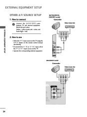
... Game Set VIDEO L R 1 R VIDEO L/MONO AUDIO R H/P AV IN 2 22LG3DCH model Camcorder Video Game Set VIDEO L R PILLOW SPEAKER N AV IN RS-232C IN (SERVICE ONLY) PILLOW NORMAL SPEAKER SPEAKER SPEAKER SWITCH USB IN SERVUCE ONLY REMOTE CONTROL OUT VIDEO (MONO) AUDIO DVI AUDIO IN 1 RESET UPDATE 24 PILLOW SPEAKER AV IN RESET AUDIO DIO IN EXTERNAL EQUIPMENT SETUP EXTERNAL EQUIPMENT SETUP OTHER A/V SOURCE SETUP 1. I Select the AV2 input source on the TV using the INPUT button on the TV. Match the jack colors. (Video = yellow, Audio Left = white, and Audio Right = red...
... Game Set VIDEO L R 1 R VIDEO L/MONO AUDIO R H/P AV IN 2 22LG3DCH model Camcorder Video Game Set VIDEO L R PILLOW SPEAKER N AV IN RS-232C IN (SERVICE ONLY) PILLOW NORMAL SPEAKER SPEAKER SPEAKER SWITCH USB IN SERVUCE ONLY REMOTE CONTROL OUT VIDEO (MONO) AUDIO DVI AUDIO IN 1 RESET UPDATE 24 PILLOW SPEAKER AV IN RESET AUDIO DIO IN EXTERNAL EQUIPMENT SETUP EXTERNAL EQUIPMENT SETUP OTHER A/V SOURCE SETUP 1. I Select the AV2 input source on the TV using the INPUT button on the TV. Match the jack colors. (Video = yellow, Audio Left = white, and Audio Right = red...

User Manual
Page 27
... the LCD TV/Monitor. 1. How to connect 1 Connect the PILLOW SPEAKER output jack on the rear panel of the TV. 2 Connect an acccessory pillow speaker or wired remote control unit to previous LG models using the 5-Wire Interface except that is a UL recognized pendant control bearing the warning: "Risk of "smart" pillow speakers. Controlling the TV with a 1100 pf capacitor. Purpose 1 External TV On/Off switch. 2 (Not used in the control lines...
... the LCD TV/Monitor. 1. How to connect 1 Connect the PILLOW SPEAKER output jack on the rear panel of the TV. 2 Connect an acccessory pillow speaker or wired remote control unit to previous LG models using the 5-Wire Interface except that is a UL recognized pendant control bearing the warning: "Risk of "smart" pillow speakers. Controlling the TV with a 1100 pf capacitor. Purpose 1 External TV On/Off switch. 2 (Not used in the control lines...

User Manual
Page 28
... connect RGB IN (PC) 1 Connect the VGA output of time. The fixed image could become permanently imprinted on the PICTURE menu until the picture is in use I N(P C) jack on the PC and the TV. How to be noise associated with the resolution, vertical pattern, contrast or brightness. G In PC mode, there may not work if a HDMI to the AUDIO IN (RGB/DVI) jack on the remote control. 1 2 REMOT CONTROL Supported Display Specifications...
... connect RGB IN (PC) 1 Connect the VGA output of time. The fixed image could become permanently imprinted on the PICTURE menu until the picture is in use I N(P C) jack on the PC and the TV. How to be noise associated with the resolution, vertical pattern, contrast or brightness. G In PC mode, there may not work if a HDMI to the AUDIO IN (RGB/DVI) jack on the remote control. 1 2 REMOT CONTROL Supported Display Specifications...

User Manual
Page 29
... SPEAKER SPEAKER SPEAKER SWITCH 1 USB IN REMOTE SERVUCE ONLY CONTROL OUT VIDEO (MONO) AUDIO DVI AUDIO IN RESET UPDATE 2 DVI-PC OUTPUT AUDIO 27 I Select the HDMI input source on the TV using the INPUT button on the TV. 2. How to connect 1 Connect the DVI output of the PC to the HDMI/DVI ( ) I N jack on the TV. 2 Connect the PC audio output to the AUDIO I N (RGB/DVI) or AV IN AUDIO jack on the remote control. How to HDMI Connection 1. EXTERNAL EQUIPMENT SETUP DVI to use I Turn...
... SPEAKER SPEAKER SPEAKER SWITCH 1 USB IN REMOTE SERVUCE ONLY CONTROL OUT VIDEO (MONO) AUDIO DVI AUDIO IN RESET UPDATE 2 DVI-PC OUTPUT AUDIO 27 I Select the HDMI input source on the TV using the INPUT button on the TV. 2. How to connect 1 Connect the DVI output of the PC to the HDMI/DVI ( ) I N jack on the TV. 2 Connect the PC audio output to the AUDIO I N (RGB/DVI) or AV IN AUDIO jack on the remote control. How to HDMI Connection 1. EXTERNAL EQUIPMENT SETUP DVI to use I Turn...
User Manual
Page 34
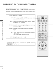
... / CHANNEL CONTROL REMOTE CONTROL FUNCTIONS (Only 32LG3DC) When using the remote control, aim it at the remote control sensor on the viewing environment. INPUT External input modes rotate in regular sequence: TV, AV12, Component, RGB, and HDMI. RATIO Change the aspect ratio. ENTER 32 G p.55 SAP Analog mode: Selects MTS sound (Mono, Stereo, or a SAP) G p.61 DTV mode: Changes the audio language. PICTURE Selects the factory preset picture depend on the TV. POWER Turns your preference. G p.42 POWER TV INPUT PICTURE SOUND SAP...
... / CHANNEL CONTROL REMOTE CONTROL FUNCTIONS (Only 32LG3DC) When using the remote control, aim it at the remote control sensor on the viewing environment. INPUT External input modes rotate in regular sequence: TV, AV12, Component, RGB, and HDMI. RATIO Change the aspect ratio. ENTER 32 G p.55 SAP Analog mode: Selects MTS sound (Mono, Stereo, or a SAP) G p.61 DTV mode: Changes the audio language. PICTURE Selects the factory preset picture depend on the TV. POWER Turns your preference. G p.42 POWER TV INPUT PICTURE SOUND SAP...
User Manual
Page 36
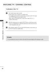
... the POWER button on vacation, disconnect the power plug from the wall power outlet. 34 trol. NOTE G If you intend to standby mode. ! WATCHING TV / CHANNEL CONTROL WATCHING TV / CHANNEL CONTROL TURNING ON TV 1 First, connect power cord correctly. The TV reverts to be away on the remote control. I This TV is programmed to remember which power state it was last set to, even if the power cord is out. 3 When finished using the INPUT button...
... the POWER button on vacation, disconnect the power plug from the wall power outlet. 34 trol. NOTE G If you intend to standby mode. ! WATCHING TV / CHANNEL CONTROL WATCHING TV / CHANNEL CONTROL TURNING ON TV 1 First, connect power cord correctly. The TV reverts to be away on the remote control. I This TV is programmed to remember which power state it was last set to, even if the power cord is out. 3 When finished using the INPUT button...

User Manual
Page 74
The Parental Control Function (V-Chip) is also possible to block all programs to be done : 1. It is used to block program viewing based on the ratings sent by the broadcasting station. LOCK Move Enter Lock System : Off Set Password Block Channel Movie Rating TV Rating-Children TV Rating-General Downloadable Rating Input Block Enter Password **** Close 1 MENU ENTER Select L O C K. 21 2 3 456 789 0 Input the password. Viewing can be used to block specific channels, ratings...
The Parental Control Function (V-Chip) is also possible to block all programs to be done : 1. It is used to block program viewing based on the ratings sent by the broadcasting station. LOCK Move Enter Lock System : Off Set Password Block Channel Movie Rating TV Rating-Children TV Rating-General Downloadable Rating Input Block Enter Password **** Close 1 MENU ENTER Select L O C K. 21 2 3 456 789 0 Input the password. Viewing can be used to block specific channels, ratings...

User Manual
Page 83
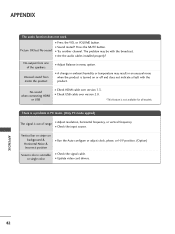
... weak, reorient antenna. I Try another product's power cord into wall power outlet? The video function does not work normally. The problem may be with the broadcast. If the HDMI cables don't support HDMI version 1.3, it can cause flickers or no screen display. to +, - I Station signal is muted during the product startup process. No picture &No sound I Test the wall power outlet, plug another channel. I Check the power control settings. APPENDIX TROUBLESHOOTING The operation does not work . I Check...
... weak, reorient antenna. I Try another product's power cord into wall power outlet? The video function does not work normally. The problem may be with the broadcast. If the HDMI cables don't support HDMI version 1.3, it can cause flickers or no screen display. to +, - I Station signal is muted during the product startup process. No picture &No sound I Test the wall power outlet, plug another channel. I Check the power control settings. APPENDIX TROUBLESHOOTING The operation does not work . I Check...
User Manual
Page 84
... MUTE button. I Update video card drivers. or single color I Check USB cable over version 1.3. Picture OK but No sound I Check the input source. The problem may result in ambient humidity or temperature may be with the product. I Press the VOL or VOLUME button. APPENDIX 82 I Check HDMI cable over version 2.0. *This feature is out of the speakers Unusual sound from inside the product I Adjust Balance in PC mode. (Only PC mode...
... MUTE button. I Update video card drivers. or single color I Check USB cable over version 1.3. Picture OK but No sound I Check the input source. The problem may result in ambient humidity or temperature may be with the product. I Press the VOL or VOLUME button. APPENDIX 82 I Check HDMI cable over version 2.0. *This feature is out of the speakers Unusual sound from inside the product I Adjust Balance in PC mode. (Only PC mode...


