
Owners Manual
Page 3
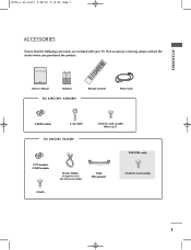
INDEX 9 FAV Owner's Manual Batteries Remote Control Power Cord For 42PC1RV*, 42PC3RV* 2-Wall brackets 2-eye-bolts For 26LC2R*, 32LC2R* 2-bolts for stand assembly 2-bolts 1 User Guide TINVPUT INPUT ARC POWER EXIT LIST PIP TEXT PR- PIP PIP PR+ TV DVD SIZE VCR PIP ...
INDEX 9 FAV Owner's Manual Batteries Remote Control Power Cord For 42PC1RV*, 42PC3RV* 2-Wall brackets 2-eye-bolts For 26LC2R*, 32LC2R* 2-bolts for stand assembly 2-bolts 1 User Guide TINVPUT INPUT ARC POWER EXIT LIST PIP TEXT PR- PIP PIP PR+ TV DVD SIZE VCR PIP ...

Owners Manual
Page 4
... (Image Sticking Minimization) Method . . .61 Low Power 62 XD Demo 63 0323G_1-en_rev01 2/28/06 4:12 PM Page 2 CONTENTS CONTENTS ACCESSORIES 1 INTRODUCTION Controls / Connection Options 4-9 Remote Control Key Functions 10-11 Installing Batteries 11 INSTALLATION Stand Installation 12-13 Basic Connection / How to Remove the Cable Management 14-15 How to...
... (Image Sticking Minimization) Method . . .61 Low Power 62 XD Demo 63 0323G_1-en_rev01 2/28/06 4:12 PM Page 2 CONTENTS CONTENTS ACCESSORIES 1 INTRODUCTION Controls / Connection Options 4-9 Remote Control Key Functions 10-11 Installing Batteries 11 INSTALLATION Stand Installation 12-13 Basic Connection / How to Remove the Cable Management 14-15 How to...
Owners Manual
Page 5
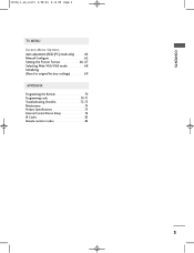
CONTENTS 0323G_1-en_rev01 2/28/06 4:12 PM Page 3 TV MENU Screen Menu Options Auto adjustment (RGB [PC] mode only 64 Manual Configure 65 Setting the Picture Format 66-67 Selecting Wide VGA/XGA mode 68 Initializing (Reset to original factory settings 69 APPENDIX Programming the Remote 70 Programming code 70-71 Troubleshooting Checklist 72-73 Maintenance 74 Product Specifications 75 External Control Device Setup 76 IR Codes 83 Remote control ir codes 84 3
CONTENTS 0323G_1-en_rev01 2/28/06 4:12 PM Page 3 TV MENU Screen Menu Options Auto adjustment (RGB [PC] mode only 64 Manual Configure 65 Setting the Picture Format 66-67 Selecting Wide VGA/XGA mode 68 Initializing (Reset to original factory settings 69 APPENDIX Programming the Remote 70 Programming code 70-71 Troubleshooting Checklist 72-73 Maintenance 74 Product Specifications 75 External Control Device Setup 76 IR Codes 83 Remote control ir codes 84 3
Owners Manual
Page 7
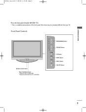
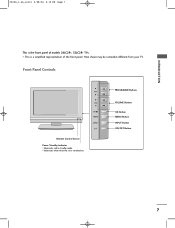
Front Panel Controls Remote Control Sensor Power/Standby Indicator • illuminates red in standby mode. • illuminates white when the set is the front panel of the front panel. INTRODUCTION 0323G_1-en_rev01 2/28/06 4:12 PM Page 5 This is switched on. Here shown may be somewhat different from your TV. I This is a simplified representation of models 42PC3RV* TVs. PR PROGRAMME Buttons VOL VOLUME Buttons OK MENU INPUT OK Button MENU Button INPUT Button ON/OFF Button 5
Front Panel Controls Remote Control Sensor Power/Standby Indicator • illuminates red in standby mode. • illuminates white when the set is the front panel of the front panel. INTRODUCTION 0323G_1-en_rev01 2/28/06 4:12 PM Page 5 This is switched on. Here shown may be somewhat different from your TV. I This is a simplified representation of models 42PC3RV* TVs. PR PROGRAMME Buttons VOL VOLUME Buttons OK MENU INPUT OK Button MENU Button INPUT Button ON/OFF Button 5
Owners Manual
Page 8
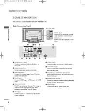
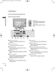
... is indicated on the Specifications page. Back Connection Panel 1 COMPONENT IN VIDEO AUDIO 1 2 AV OUT 23 4 RGB IN (PC/DTV) HDMI IN REMOTE AUDIO IN CONTROL IN (RGB) VARIABLE AUDIO OUT 42PC1RV* only AV IN 2 AUDIO Input R Connections are available for listening AUDIO stereo sound from an... external device to these jacks. 2 Remote Control Port Connect your surround sound system. 11 Antenna Input Connect over-the-air signals to HDMI port with HDMI cable. 5 Power Cord Socket ...
... is indicated on the Specifications page. Back Connection Panel 1 COMPONENT IN VIDEO AUDIO 1 2 AV OUT 23 4 RGB IN (PC/DTV) HDMI IN REMOTE AUDIO IN CONTROL IN (RGB) VARIABLE AUDIO OUT 42PC1RV* only AV IN 2 AUDIO Input R Connections are available for listening AUDIO stereo sound from an... external device to these jacks. 2 Remote Control Port Connect your surround sound system. 11 Antenna Input Connect over-the-air signals to HDMI port with HDMI cable. 5 Power Cord Socket ...
Owners Manual
Page 9
I PROGRAMME Buttons VOLUME Buttons OK Button MENU Button INPUT Button ON/OFF Button 7 Here shown may be somewhat different from your TV. INTRODUCTION 0323G_1-en_rev01 2/28/06 4:12 PM Page 7 This is a simplified representation of models 26LC2R*, 32LC2R* TVs. Front Panel Controls PR R Remote Control Sensor Power/Standby Indicator • illuminates red in standby mode. • illuminates white when the set is switched on. VOL OK MENU INPUT /I This is the front panel of the front panel.
I PROGRAMME Buttons VOLUME Buttons OK Button MENU Button INPUT Button ON/OFF Button 7 Here shown may be somewhat different from your TV. INTRODUCTION 0323G_1-en_rev01 2/28/06 4:12 PM Page 7 This is a simplified representation of models 26LC2R*, 32LC2R* TVs. Front Panel Controls PR R Remote Control Sensor Power/Standby Indicator • illuminates red in standby mode. • illuminates white when the set is switched on. VOL OK MENU INPUT /I This is the front panel of the front panel.
Owners Manual
Page 10
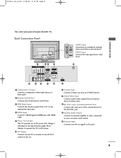
.... 11 Antenna Input Connect over-the-air signals to these jacks. 9 RS-232C Input (CONTROL&SERVICE) Port Connect the serial port of models 26LC2R* TVs. The voltage is the back panel of the control devices to the RS-232C jack. 10 Variable Audio Output Connect an external amplifier or... available for listening stereo sound from a video AC IN AV IN 2 device. 1 COMPONENT IN VIDEO AUDIO 1 2 AV OUT 23 4 RGB IN (PC/DTV) HDMI IN REMOTE AUDIO IN CONTROL IN (RGB) VARIABLE AUDIO OUT 5 AC IN S-VIDEO VIDEO (MONO) AUDIO RS-232C IN (CONTROL & SERVICE) 6 7 8 9 10 ANTENNA IN 11 1 ...
.... 11 Antenna Input Connect over-the-air signals to these jacks. 9 RS-232C Input (CONTROL&SERVICE) Port Connect the serial port of models 26LC2R* TVs. The voltage is the back panel of the control devices to the RS-232C jack. 10 Variable Audio Output Connect an external amplifier or... available for listening stereo sound from a video AC IN AV IN 2 device. 1 COMPONENT IN VIDEO AUDIO 1 2 AV OUT 23 4 RGB IN (PC/DTV) HDMI IN REMOTE AUDIO IN CONTROL IN (RGB) VARIABLE AUDIO OUT 5 AC IN S-VIDEO VIDEO (MONO) AUDIO RS-232C IN (CONTROL & SERVICE) 6 7 8 9 10 ANTENNA IN 11 1 ...
Owners Manual
Page 11
... VIDEO Input Connects the video signal from a video AV IN 2 device. 1 COMPONENT IN VIDEO AUDIO 1 2 AV OUT 23 4 RGB IN (PC/DTV) HDMI IN REMOTE AUDIO IN CONTROL IN (RGB) VARIABLE AUDIO OUT 5 AC IN AV IN 1 S-VIDEO VIDEO (MONO) AUDIO RS-232C IN (CONTROL & SERVICE) 6 7 8 9 10...an external amplifier or add a subwoofer to your surround sound system. 11 Antenna Input Connect over-the-air signals to these jacks. 2 Remote Control Port Connect your wired remote control here. 3 RGB/Audio Input Connect the monitor output from a PC to the appropriate input port. 4 HDMI Input Connect a ...
... VIDEO Input Connects the video signal from a video AV IN 2 device. 1 COMPONENT IN VIDEO AUDIO 1 2 AV OUT 23 4 RGB IN (PC/DTV) HDMI IN REMOTE AUDIO IN CONTROL IN (RGB) VARIABLE AUDIO OUT 5 AC IN AV IN 1 S-VIDEO VIDEO (MONO) AUDIO RS-232C IN (CONTROL & SERVICE) 6 7 8 9 10...an external amplifier or add a subwoofer to your surround sound system. 11 Antenna Input Connect over-the-air signals to these jacks. 2 Remote Control Port Connect your wired remote control here. 3 RGB/Audio Input Connect the monitor output from a PC to the appropriate input port. 4 HDMI Input Connect a ...
Owners Manual
Page 12
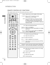
... TELETEXT buttons models) or Programme edit. MENU Selects a menu. 0323G_1-en_rev01 2/28/06 4:12 PM Page 10 INTRODUCTION INTRODUCTION REMOTE CONTROL KEY FUNCTIONS When using the remote control, aim it at the remote control sensor on from standby. Press the D / E button and then OK button to the default settings brightness by changing mode...
... TELETEXT buttons models) or Programme edit. MENU Selects a menu. 0323G_1-en_rev01 2/28/06 4:12 PM Page 10 INTRODUCTION INTRODUCTION REMOTE CONTROL KEY FUNCTIONS When using the remote control, aim it at the remote control sensor on from standby. Press the D / E button and then OK button to the default settings brightness by changing mode...
Owners Manual
Page 13
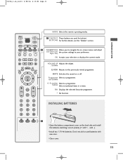
... settings to navigate the on or off. TIME REVEAL INDEX 1 I Close cover. 11 0323G_1-en_rev01 2/28/06 4:12 PM Page 11 INTRODUCTION MODE Selects the remote operating modes. OK Accepts your preference. INPUT TV POWER INPUT TV DVD 1 TELETEXT These buttons are used batteries with -). BUTTONS For further details, see the...
... settings to navigate the on or off. TIME REVEAL INDEX 1 I Close cover. 11 0323G_1-en_rev01 2/28/06 4:12 PM Page 11 INTRODUCTION MODE Selects the remote operating modes. OK Accepts your preference. INPUT TV POWER INPUT TV DVD 1 TELETEXT These buttons are used batteries with -). BUTTONS For further details, see the...
Owners Manual
Page 21
... button on the screen. If the 4:3 picture format is used; If connected to the AUDIO L/MONO jack of the screen may remain visible on the remote control. -
... button on the screen. If the 4:3 picture format is used; If connected to the AUDIO L/MONO jack of the screen may remain visible on the remote control. -
Owners Manual
Page 22
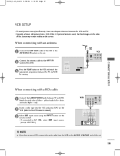
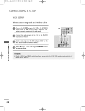
... When connecting with an S-Video cable AV IN 1 1 2 S-VIDEO VIDEO ( ) AUDIO 1 Connect the S-VIDEO output of the VCR to the AUDIO input jacks on the remote control.
... When connecting with an S-Video cable AV IN 1 1 2 S-VIDEO VIDEO ( ) AUDIO 1 Connect the S-VIDEO output of the VCR to the AUDIO input jacks on the remote control.
Owners Manual
Page 23
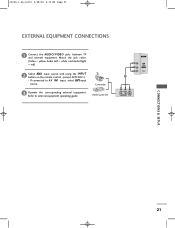
If connected to external equipment operating guide. Video Game Set AV IN 2 R AUDIO L/MONO VIDEO 1 R AUDIO L VIDEO CONNECTIONS & SETUP 21 Camcorder 3 Operate the corresponding external equipment. Match the jack colors (Video = yellow, Audio Left = white, and Audio Right = red) 2 Select AV2 input source with using the INPUT button on the remote control. (except 42PC3RV*) - 0323G_1-en_rev01 2/28/06 4:12 PM Page 21 EXTERNAL EQUIPMENT CONNECTIONS 1 Connect the AUDIO/VIDEO jacks between TV and external equipment. Refer to AV IN1 input, select AV1input source.
If connected to external equipment operating guide. Video Game Set AV IN 2 R AUDIO L/MONO VIDEO 1 R AUDIO L VIDEO CONNECTIONS & SETUP 21 Camcorder 3 Operate the corresponding external equipment. Match the jack colors (Video = yellow, Audio Left = white, and Audio Right = red) 2 Select AV2 input source with using the INPUT button on the remote control. (except 42PC3RV*) - 0323G_1-en_rev01 2/28/06 4:12 PM Page 21 EXTERNAL EQUIPMENT CONNECTIONS 1 Connect the AUDIO/VIDEO jacks between TV and external equipment. Refer to AV IN1 input, select AV1input source.
Owners Manual
Page 24
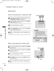
... the AUDIO input jacks on the set . 3 Turn on the DVD player, insert a DVD. 4 Select Component input source with using the INPUT button on the remote control. 5 Refer to the DVD player's manual for operating instructions. When connecting with using the INPUT button on the... remote control. 5 Refer to the comp2 onent input ports as shown below. AV IN 1 DVD (R) AUDIO (L) S-VIDEO COMPONENT IN VIDEO AUDIO 1 2 2 AV OUT S-VIDEO VIDEO (MONO) ...
... the AUDIO input jacks on the set . 3 Turn on the DVD player, insert a DVD. 4 Select Component input source with using the INPUT button on the remote control. 5 Refer to the DVD player's manual for operating instructions. When connecting with using the INPUT button on the... remote control. 5 Refer to the comp2 onent input ports as shown below. AV IN 1 DVD (R) AUDIO (L) S-VIDEO COMPONENT IN VIDEO AUDIO 1 2 2 AV OUT S-VIDEO VIDEO (MONO) ...
Owners Manual
Page 25
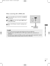
... the HDMI output of the DVD to the HDMI IN jack on the set. 2 Select HDMI input source with using the INPUT button on the remote control. To get the best picture quality, adjust the output resolution of the DVD to 1280x720p. AV IN 3 S-VIDEO VIDEO ( ) AUDIO CONNECTIONS & SETUP ...23 VIDEO AUDIO RGB IN (PC/DTV) HDMI IN REMOTE AUDIO IN CONTROL IN (RGB) VARIABLE AUDIO OUT RS-232C IN (CONTROL&SERVICE) 1 DVD HDMI-DVD OUTPUT ! G If the DVD does not support Auto HDMI...
... the HDMI output of the DVD to the HDMI IN jack on the set. 2 Select HDMI input source with using the INPUT button on the remote control. To get the best picture quality, adjust the output resolution of the DVD to 1280x720p. AV IN 3 S-VIDEO VIDEO ( ) AUDIO CONNECTIONS & SETUP ...23 VIDEO AUDIO RGB IN (PC/DTV) HDMI IN REMOTE AUDIO IN CONTROL IN (RGB) VARIABLE AUDIO OUT RS-232C IN (CONTROL&SERVICE) 1 DVD HDMI-DVD OUTPUT ! G If the DVD does not support Auto HDMI...

Owners Manual
Page 26
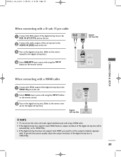
... set-top box. (Refer to the owner's manual for the digital set-top box.) 4 Select HDMI input source with using the INPUT button on the remote control. G If the digital set-top box does not support Auto DVI, you need to set -top box to the owner's manual for the digital... set-top box.) 4 Select Component input source with using the INPUT button on the remote control. 1 2 AV IN 1 S-VIDEO VIDEO ( ) AUDIO RGB IN (PC/DTV) HDMI IN REMOTE AUDIO IN CONTROL IN (RGB) VARIABLE AUDIO OUT RS-232C IN (CONTROL&SERVICE) 1 2 Digital Set-top Box DVI-DTV...
... set-top box. (Refer to the owner's manual for the digital set-top box.) 4 Select HDMI input source with using the INPUT button on the remote control. G If the digital set-top box does not support Auto DVI, you need to set -top box to the owner's manual for the digital... set-top box.) 4 Select Component input source with using the INPUT button on the remote control. 1 2 AV IN 1 S-VIDEO VIDEO ( ) AUDIO RGB IN (PC/DTV) HDMI IN REMOTE AUDIO IN CONTROL IN (RGB) VARIABLE AUDIO OUT RS-232C IN (CONTROL&SERVICE) 1 2 Digital Set-top Box DVI-DTV...
Owners Manual
Page 27
... function, output resolution of the digital set-top box will be automatically set to set the output resolution appropri- ately. COMPONENT IN 3 Turn on the remote control. To get the best picture quality, adjust the output resolution of the digital set-top box to the owner's man- AV IN 3 S-VIDEO VIDEO... on the digital set-top box. (Refer to the owner's manual for the digital set-top box.) VIDEO AUDIO RGB IN (PC/DTV) HDMI IN REMOTE AUDIO IN CONTROL IN (RGB) VARIABLE AUDIO OUT RS-232C IN (CONTROL&SERVICE) 1 Digital Set-top Box HDMI-DVD OUTPUT !
... function, output resolution of the digital set-top box will be automatically set to set the output resolution appropri- ately. COMPONENT IN 3 Turn on the remote control. To get the best picture quality, adjust the output resolution of the digital set-top box to the owner's man- AV IN 3 S-VIDEO VIDEO... on the digital set-top box. (Refer to the owner's manual for the digital set-top box.) VIDEO AUDIO RGB IN (PC/DTV) HDMI IN REMOTE AUDIO IN CONTROL IN (RGB) VARIABLE AUDIO OUT RS-232C IN (CONTROL&SERVICE) 1 Digital Set-top Box HDMI-DVD OUTPUT !
Owners Manual
Page 28
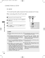
... and sound, connect a PC to the TV's settings. use a screen saver when possible. 6 We recommend using 640x480, 60Hz (42PC1RV*, 42PC3RV*) /1024x768, 60Hz (26LC2R*, 32LC2R*) for the PC mode, they provide the best picture quality. 3 Connect PC to the TV's AUDIO IN (RGB) input. 3 Turn on the PC. ...into other resolution or change the refresh rate into other rate or adjust the brightness and contrast on the remote control. (R) AUDIO (L) RGB-DTV OUTPUT PC 2 1 RGB IN (PC/DTV) HDMI IN REMOTE AUDIO IN CONTROL IN (RGB) VARIABLE AUDIO OUT RS-232C IN (CONTROL&SERVICE) CONNECTIONS & SETUP !...
... and sound, connect a PC to the TV's settings. use a screen saver when possible. 6 We recommend using 640x480, 60Hz (42PC1RV*, 42PC3RV*) /1024x768, 60Hz (26LC2R*, 32LC2R*) for the PC mode, they provide the best picture quality. 3 Connect PC to the TV's AUDIO IN (RGB) input. 3 Turn on the PC. ...into other resolution or change the refresh rate into other rate or adjust the brightness and contrast on the remote control. (R) AUDIO (L) RGB-DTV OUTPUT PC 2 1 RGB IN (PC/DTV) HDMI IN REMOTE AUDIO IN CONTROL IN (RGB) VARIABLE AUDIO OUT RS-232C IN (CONTROL&SERVICE) CONNECTIONS & SETUP !...
Owners Manual
Page 30
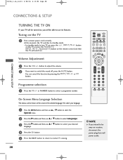
I In standby mode to select a programme number. button on the TV or press the POWER, TV, INPUT, PR +/-, Number(0~9) button on the remote control and then the TV will be able to standby mode. or I /II EXIT SLEEP OK Q.VIEW VOL PR MUTE 1 2 3 4 5 6 7 8 9 * 0 FAV TIME ? REVEAL INDEX On-...
I In standby mode to select a programme number. button on the TV or press the POWER, TV, INPUT, PR +/-, Number(0~9) button on the remote control and then the TV will be able to standby mode. or I /II EXIT SLEEP OK Q.VIEW VOL PR MUTE 1 2 3 4 5 6 7 8 9 * 0 FAV TIME ? REVEAL INDEX On-...

Owners Manual
Page 62
... feature can be used to remember which option it . NOTE G In Child lock 'O n', if the set is pressed while viewing the set so that the remote control is programmed to prevent unauthorized viewing. button on the set off , press the r / I /II EXIT SLEEP OK Q.VIEW VOL PR MUTE 1 2 3 4 5 6 Special Language...DE F G OK MENU 23 TV MENU ! G With the Child lock O n, the display 'Child lock on' appears on the screen if any button on the remote control. TEXT PIP SIZE POSTION PIP PR- This set is needed to control it was last set to the previous menu. PIP PR+ PIP INPUT...
... feature can be used to remember which option it . NOTE G In Child lock 'O n', if the set is pressed while viewing the set so that the remote control is programmed to prevent unauthorized viewing. button on the set off , press the r / I /II EXIT SLEEP OK Q.VIEW VOL PR MUTE 1 2 3 4 5 6 Special Language...DE F G OK MENU 23 TV MENU ! G With the Child lock O n, the display 'Child lock on' appears on the screen if any button on the remote control. TEXT PIP SIZE POSTION PIP PR- This set is needed to control it was last set to the previous menu. PIP PR+ PIP INPUT...


