
Owners Manual
Page 1
LCD TV PLASMA TV OWNER'S MANUAL LCD TV MODELS PLASMA TV MODELS 26LC2R* 32LC2R* 42PC1RV* 42PC3RV* Please read Information Manual included together before reading this information to your set . Record model number and serial number of the set . P/NO : 38289U0323G (0602-REV00) Printed in Korea See the label attached on the back cover and quote this manual and operating your dealer when you require service. Retain it for future reference.
LCD TV PLASMA TV OWNER'S MANUAL LCD TV MODELS PLASMA TV MODELS 26LC2R* 32LC2R* 42PC1RV* 42PC3RV* Please read Information Manual included together before reading this information to your set . Record model number and serial number of the set . P/NO : 38289U0323G (0602-REV00) Printed in Korea See the label attached on the back cover and quote this manual and operating your dealer when you require service. Retain it for future reference.
Owners Manual
Page 25
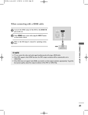
... with using a HDMI cable. VIDEO AUDIO RGB IN (PC/DTV) HDMI IN REMOTE AUDIO IN CONTROL IN (RGB) VARIABLE AUDIO OUT RS-232C IN (CONTROL&SERVICE) 1 DVD HDMI-DVD OUTPUT ! To get the best picture quality, adjust the output resolution of the DVD to the HDMI IN jack on the set... 4:12 PM Page 23 When connecting with a HDMI cable 1 Connect the HDMI output of the DVD to 1280x720p. COMPONENT IN 3 Refer to the DVD player's manual for operating instruc-
... with using a HDMI cable. VIDEO AUDIO RGB IN (PC/DTV) HDMI IN REMOTE AUDIO IN CONTROL IN (RGB) VARIABLE AUDIO OUT RS-232C IN (CONTROL&SERVICE) 1 DVD HDMI-DVD OUTPUT ! To get the best picture quality, adjust the output resolution of the DVD to the HDMI IN jack on the set... 4:12 PM Page 23 When connecting with a HDMI cable 1 Connect the HDMI output of the DVD to 1280x720p. COMPONENT IN 3 Refer to the DVD player's manual for operating instruc-

Owners Manual
Page 26
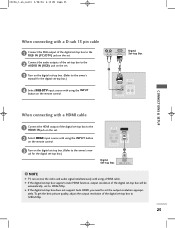
... of the set-top box to the AUDIO IN (RGB) jack on the set. 3 Turn on the digital set-top box. (Refer to the owner's manual for the digital set-top box.) 4 Select Component input source with using the INPUT button on the remote control. 1 2 AV IN 1 S-VIDEO VIDEO ( ) AUDIO... RGB IN (PC/DTV) HDMI IN REMOTE AUDIO IN CONTROL IN (RGB) VARIABLE AUDIO OUT RS-232C IN (CONTROL&SERVICE) 1 2 Digital Set-top Box DVI-DTV OUTPUT (R) AUDIO (L) ! 0323G_1-en_rev01 2/28/06 4:12 PM Page 24 CONNECTIONS & SETUP STB (SET-TOP BOX) SETUP When ...
... of the set-top box to the AUDIO IN (RGB) jack on the set. 3 Turn on the digital set-top box. (Refer to the owner's manual for the digital set-top box.) 4 Select Component input source with using the INPUT button on the remote control. 1 2 AV IN 1 S-VIDEO VIDEO ( ) AUDIO... RGB IN (PC/DTV) HDMI IN REMOTE AUDIO IN CONTROL IN (RGB) VARIABLE AUDIO OUT RS-232C IN (CONTROL&SERVICE) 1 2 Digital Set-top Box DVI-DTV OUTPUT (R) AUDIO (L) ! 0323G_1-en_rev01 2/28/06 4:12 PM Page 24 CONNECTIONS & SETUP STB (SET-TOP BOX) SETUP When ...
Owners Manual
Page 27
...IN (PC/DTV) HDMI IN REMOTE AUDIO IN CONTROL IN (RGB) VARIABLE AUDIO OUT RS-232C IN (CONTROL&SERVICE) CONNECTIONS & SETUP When connecting with a HDMI cable 1 Connect the HDMI output of the digital set-top box...a HDMI cable. 0323G_1-en_rev01 2/28/06 4:12 PM Page 25 VARIABLE AUDIO OUT RS-232C IN (CONTROL & SERVICE) When connecting with a D-sub 15 pin cable 1 Connect the RGB output of the digital set-top box to...RGB) jack on the set. 3 Turn on the digital set-top box. (Refer to the owner's manual for the digital set-top box.) VIDEO AUDIO RGB IN (PC/DTV) HDMI IN REMOTE AUDIO IN CONTROL ...
...IN (PC/DTV) HDMI IN REMOTE AUDIO IN CONTROL IN (RGB) VARIABLE AUDIO OUT RS-232C IN (CONTROL&SERVICE) CONNECTIONS & SETUP When connecting with a HDMI cable 1 Connect the HDMI output of the digital set-top box...a HDMI cable. 0323G_1-en_rev01 2/28/06 4:12 PM Page 25 VARIABLE AUDIO OUT RS-232C IN (CONTROL & SERVICE) When connecting with a D-sub 15 pin cable 1 Connect the RGB output of the digital set-top box to...RGB) jack on the set. 3 Turn on the digital set-top box. (Refer to the owner's manual for the digital set-top box.) VIDEO AUDIO RGB IN (PC/DTV) HDMI IN REMOTE AUDIO IN CONTROL ...
Service Manual
Page 1
R website:http://biz.LGservice.com e-mail:http://www.LGEservice.com/techsup.html LCD TV SERVICE MANUAL CHASSIS : LP61C FACTORY MODEL : 26LC2R-TJ / 32LC2R-TJ MODEL : 26LC2R / 32LC2R CAUTION BEFORE SERVICING THE CHASSIS, READ THE SAFETY PRECAUTIONS IN THIS MANUAL.
R website:http://biz.LGservice.com e-mail:http://www.LGEservice.com/techsup.html LCD TV SERVICE MANUAL CHASSIS : LP61C FACTORY MODEL : 26LC2R-TJ / 32LC2R-TJ MODEL : 26LC2R / 32LC2R CAUTION BEFORE SERVICING THE CHASSIS, READ THE SAFETY PRECAUTIONS IN THIS MANUAL.

Service Manual
Page 3
...electrical shock. It is not isolated from the AC power line. Do not modify the original design without damage of tolerance, immediate service and correction is blown, replace it 's components from being damaged by in this chassis have special safety-related characteristics. The meter ...10mm away from high voltage or high temperature parts. For continued X-RAY RADIATION protection, the replacement panel must be used during this manual to the AC plug prongs tied together and touch other Hazards. Adjust brightness, color, contrast controls to the customer, always perform an...
...electrical shock. It is not isolated from the AC power line. Do not modify the original design without damage of tolerance, immediate service and correction is blown, replace it 's components from being damaged by in this chassis have special safety-related characteristics. The meter ...10mm away from high voltage or high temperature parts. For continued X-RAY RADIATION protection, the replacement panel must be used during this manual to the AC plug prongs tied together and touch other Hazards. Adjust brightness, color, contrast controls to the customer, always perform an...

Service Manual
Page 4
...) devices can generate static electricity sufficient to damage an ES device.) General Soldering Guidelines 1. Examples of contacts in this service manual, lubrication of typical ES devices are called Electrostatically Sensitive (ES) Devices. Use only an anti-static type solder removal...use freon-propelled spray-on page 3 of the assembly. 3. Use the following unsoldering technique a. SERVICING PRECAUTIONS CAUTION: Before servicing receivers covered by this service manual and its protective package until immediately before you are ready to install it. (Most replacement ES devices...
...) devices can generate static electricity sufficient to damage an ES device.) General Soldering Guidelines 1. Examples of contacts in this service manual, lubrication of typical ES devices are called Electrostatically Sensitive (ES) Devices. Use only an anti-static type solder removal...use freon-propelled spray-on page 3 of the assembly. 3. Use the following unsoldering technique a. SERVICING PRECAUTIONS CAUTION: Before servicing receivers covered by this service manual and its protective package until immediately before you are ready to install it. (Most replacement ES devices...


