Service Manual
Page 6
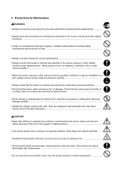
...8226; Always follow the procedures for routine replacement 2. Precautions for Maintenance WARNING • Always remove the power plug from the printer except for maintenance described in the service manual and other related brochures...• Under no circumstances attempt to bypass or disable safety ...protective circuits • Always use parts having the correct specifications Always use the thermostat or thermal fuse specified in machines using lasers. Check that the fixing unit thermistor, heat and press rollers are safely secured so they will not be extremely hot •...
...8226; Always follow the procedures for routine replacement 2. Precautions for Maintenance WARNING • Always remove the power plug from the printer except for maintenance described in the service manual and other related brochures...• Under no circumstances attempt to bypass or disable safety ...protective circuits • Always use parts having the correct specifications Always use the thermostat or thermal fuse specified in machines using lasers. Check that the fixing unit thermistor, heat and press rollers are safely secured so they will not be extremely hot •...

Service Manual
Page 10
... of parts ...1-6 1-3 Safety information ...1-7 1-3-1 Safety information ...1-7 (1) Laser safety ...1-7 (2) Laser notice ...1-7 (3) Laser caution label on the scanner unit 1-7 (4) CDRH regulations (U.S.A 1-9 (5) Ozone concentration ...1-9 (6) Optional equipment ...1-9 (7) Important note on the interface connectors 1-9 1-4 Environmental requirements ...1-10 1-4-1 Environmental conditions ...1-10 (1) Clearance ...1-11 (2) Places to avoid ...1-12 (3) Note on power ...1-12 (4) Removing the printer ...1-13 1-5 About the toner container ...1-14...
... of parts ...1-6 1-3 Safety information ...1-7 1-3-1 Safety information ...1-7 (1) Laser safety ...1-7 (2) Laser notice ...1-7 (3) Laser caution label on the scanner unit 1-7 (4) CDRH regulations (U.S.A 1-9 (5) Ozone concentration ...1-9 (6) Optional equipment ...1-9 (7) Important note on the interface connectors 1-9 1-4 Environmental requirements ...1-10 1-4-1 Environmental conditions ...1-10 (1) Clearance ...1-11 (2) Places to avoid ...1-12 (3) Note on power ...1-12 (4) Removing the printer ...1-13 1-5 About the toner container ...1-14...
Service Manual
Page 11
... of output trays (80 g/m2 [0.11 mm thickness]) Specification Electrophotography laser scan 14 pages/min. (A4) 15 pages/min. (Letter) Fast 1200 mode (1800 horizontal/600 vertical) 600 horizontal/600 vertical KIR (Kyocera Image Refinement) 22 seconds or less 10 seconds or less (from sleep...reached first Mono component developer Visible laser Scorotron positive charging Negative charger roller Curvature separation Blade Eraser lamp (LED array) Heat roller and press roller Plain paper: Legal to A5 Cassette: 250 sheets, MP tray: 50 sheets Face-up: 30 sheets, Face-down: 150 sheets FS-1050 1-3
... of output trays (80 g/m2 [0.11 mm thickness]) Specification Electrophotography laser scan 14 pages/min. (A4) 15 pages/min. (Letter) Fast 1200 mode (1800 horizontal/600 vertical) 600 horizontal/600 vertical KIR (Kyocera Image Refinement) 22 seconds or less 10 seconds or less (from sleep...reached first Mono component developer Visible laser Scorotron positive charging Negative charger roller Curvature separation Blade Eraser lamp (LED array) Heat roller and press roller Plain paper: Legal to A5 Cassette: 250 sheets, MP tray: 50 sheets Face-up: 30 sheets, Face-down: 150 sheets FS-1050 1-3
Service Manual
Page 15
... cautionary statements and figures when handling the laser scanner unit. FS-1050 1-7 Since radiation emitted inside the printer is completely confined within protective housings and external covers, the laser beam cannot escape from the printer during any phase of 1968. 1-3 Safety information 1-3-1 Safety information (1) Laser safety This printer is certified as a Class I laser product conforming to the requirements of...
... cautionary statements and figures when handling the laser scanner unit. FS-1050 1-7 Since radiation emitted inside the printer is completely confined within protective housings and external covers, the laser beam cannot escape from the printer during any phase of 1968. 1-3 Safety information 1-3-1 Safety information (1) Laser safety This printer is certified as a Class I laser product conforming to the requirements of...
Service Manual
Page 17
... in a confined area where ventilation is mandatory for laser products on the interface connectors Be sure to turn off printer power before connecting or disconnecting an interface cable to install the printer in use capped using the protective cap supplied. To... electronics through the interface connector(s), keep any interface connector which may be attached to laser products manufactured after August 1, 1976. FS-1050 1-9 Compliance is blocked. (6) Optional equipment The printer may concentrate in the United States. A label indicating compliance with the CDRH regulations ...
... in a confined area where ventilation is mandatory for laser products on the interface connectors Be sure to turn off printer power before connecting or disconnecting an interface cable to install the printer in use capped using the protective cap supplied. To... electronics through the interface connector(s), keep any interface connector which may be attached to laser products manufactured after August 1, 1976. FS-1050 1-9 Compliance is blocked. (6) Optional equipment The printer may concentrate in the United States. A label indicating compliance with the CDRH regulations ...

Service Manual
Page 20
FS-1050 1-12 (2) Places to avoid Avoid installing the printer in the printer's AC primary circuit, an easily accessible socket outlet must be provided near the equipment. Dust and smoke may give an electric shock. • Before performing ... and humidity.) • Avoid enclosed spaces that block ventilation. • Avoid sites more than 6,500 feet or 2,000 meters above sea level. (3) Note on the laser scanner window, causing print quality problem. • Vibration. • Ammonia fumes or other electrical part. • An easily accessible socket outlet must be provided near...
FS-1050 1-12 (2) Places to avoid Avoid installing the printer in the printer's AC primary circuit, an easily accessible socket outlet must be provided near the equipment. Dust and smoke may give an electric shock. • Before performing ... and humidity.) • Avoid enclosed spaces that block ventilation. • Avoid sites more than 6,500 feet or 2,000 meters above sea level. (3) Note on the laser scanner window, causing print quality problem. • Vibration. • Ammonia fumes or other electrical part. • An easily accessible socket outlet must be provided near...

Service Manual
Page 62
...step is developed on the photosensitive drum, finally fusing on the printer's electrophotography system. 4-1-1 Electrophotographic cycle The electrophotography system of the printer performs a cyclic action made of six steps as follows. Process unit Laser scaner unit 1 Main charging 2 Exposure 6 Cleaning Drum 3 ...used in laser printing which transfer data representing texts or graphics objects into a visible image which is technically explained in one Process unit PU-42. This section provides technical details on paper, using light beam generated by a laser diode. FS-1050 4-3
...step is developed on the photosensitive drum, finally fusing on the printer's electrophotography system. 4-1-1 Electrophotographic cycle The electrophotography system of the printer performs a cyclic action made of six steps as follows. Process unit Laser scaner unit 1 Main charging 2 Exposure 6 Cleaning Drum 3 ...used in laser printing which transfer data representing texts or graphics objects into a visible image which is technically explained in one Process unit PU-42. This section provides technical details on paper, using light beam generated by a laser diode. FS-1050 4-3

Service Manual
Page 84
...R38 GND PLGRDYN R32 1700.8 Hz 2 3 Q10 R41 C18 1 GND +24V + Laser scanner unit Polygon motor PGND 5 4 3 2 1 YC06 PGND +24V PGND PLGDRN PLGRDYN PLGCLK 17,008 rpm PLL control IC (IC1) Figure 4-3-7 Polygon motor control circuit 4-25 FS-1050 To begin printing, the engine CPU U01 turns PLGDR to H level, the PLL... board supplies the 1700.8 Hz clock pulse (PLGCLK) via the engine board to L level within 8 seconds since PLGDRN has been L level, the printer displays "Call service 4000". On the contrary, if PLGRDYN does not turn to the PLL control IC (IC1) for the polygon motor.
...R38 GND PLGRDYN R32 1700.8 Hz 2 3 Q10 R41 C18 1 GND +24V + Laser scanner unit Polygon motor PGND 5 4 3 2 1 YC06 PGND +24V PGND PLGDRN PLGRDYN PLGCLK 17,008 rpm PLL control IC (IC1) Figure 4-3-7 Polygon motor control circuit 4-25 FS-1050 To begin printing, the engine CPU U01 turns PLGDR to H level, the PLL... board supplies the 1700.8 Hz clock pulse (PLGCLK) via the engine board to L level within 8 seconds since PLGDRN has been L level, the printer displays "Call service 4000". On the contrary, if PLGRDYN does not turn to the PLL control IC (IC1) for the polygon motor.

Service Manual
Page 91
FS-1050 5-3 These screw symbol numbers are listed in the Ecosys Screw catalog. CAUTION When securing a self-tapping screws, align it counterclockwise, then slowly clockwise. CAUTION The printer use electrostatic sensitive parts inside (on circuit boards, Laser scanner unit, etc.). Do not overtighten. Provide... make sure that can effectively discharge your body before touching the circuit boards, the laser scanner unit, etc. WARNING Never attempt to operate the printer with the thread carefully. 5-1 General instructions This chapter provides procedures for the removal ...
FS-1050 5-3 These screw symbol numbers are listed in the Ecosys Screw catalog. CAUTION When securing a self-tapping screws, align it counterclockwise, then slowly clockwise. CAUTION The printer use electrostatic sensitive parts inside (on circuit boards, Laser scanner unit, etc.). Do not overtighten. Provide... make sure that can effectively discharge your body before touching the circuit boards, the laser scanner unit, etc. WARNING Never attempt to operate the printer with the thread carefully. 5-1 General instructions This chapter provides procedures for the removal ...

Service Manual
Page 122
... error 6-16 (9) Call service F020 - Fuser unit error 6-14 (7) Call service 5300 - Eraser lamp error 6-15 (8) Call service F010 - Main motor error 6-9 (4) Call service 4000 - Laser scanner unit [Pin photo diode] error 6-12 (6) Call service 6110 - Controller RAM read/write error 6-16 6-1-3 Print quality problems ...6-17 (1) Completely blank printout 6-18 (2) All... gauge ...6-26 6-1-4 Correcting a paper jam ...6-27 (1) Jam at the face-down and face-up trays 6-27 (2) Jam at the paper cassette 6-28 (3) Jam inside the printer ...6-28
... error 6-16 (9) Call service F020 - Fuser unit error 6-14 (7) Call service 5300 - Eraser lamp error 6-15 (8) Call service F010 - Main motor error 6-9 (4) Call service 4000 - Laser scanner unit [Pin photo diode] error 6-12 (6) Call service 6110 - Controller RAM read/write error 6-16 6-1-3 Print quality problems ...6-17 (1) Completely blank printout 6-18 (2) All... gauge ...6-26 6-1-4 Correcting a paper jam ...6-27 (1) Jam at the face-down and face-up trays 6-27 (2) Jam at the paper cassette 6-28 (3) Jam inside the printer ...6-28


