Dimension Guide
Page 1
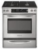
....2 cm) minimum clearance between the top of the cooking platform and the bottom of an uncovered wood or metal cabinet. Ref. ® 30" Freestanding and Slide-In Dual Fuel Range PRODUCT MODEL NUMBERS PRODUCT DIMENSIONS KDRS807S KDRS807X KDSS907S KDSS907X GAS SUPPLY REQUIREMENTS Provide a gas supply line of ³⁄₄" (1.9 cm) rigid pipe to countertop...
....2 cm) minimum clearance between the top of the cooking platform and the bottom of an uncovered wood or metal cabinet. Ref. ® 30" Freestanding and Slide-In Dual Fuel Range PRODUCT MODEL NUMBERS PRODUCT DIMENSIONS KDRS807S KDRS807X KDSS907S KDSS907X GAS SUPPLY REQUIREMENTS Provide a gas supply line of ³⁄₄" (1.9 cm) rigid pipe to countertop...
Installation Guide
Page 2
... symbol alerts you to reduce the chance of others . Canada Only 8 Gas Supply Requirements 8 Countertop Preparation 9 INSTALLATION INSTRUCTIONS 10 Unpack Range 10 Measure for Proper Height 10 Adjust Leveling Legs 10 Install Anti-Tip Bracket 11 Remove Warming Drawer 11 Electrical Connection - All safety ...de l'alimentation en gaz 28 Préparation du plan de travail 29 INSTRUCTIONS D'INSTALLATION 30 Déballage de la cuisinière 30 Mesures pour une hauteur appropriée 30 Réglage des pieds de nivellement 31 Installation de la bride antibasculement 31 Retrait du ...
... symbol alerts you to reduce the chance of others . Canada Only 8 Gas Supply Requirements 8 Countertop Preparation 9 INSTALLATION INSTRUCTIONS 10 Unpack Range 10 Measure for Proper Height 10 Adjust Leveling Legs 10 Install Anti-Tip Bracket 11 Remove Warming Drawer 11 Electrical Connection - All safety ...de l'alimentation en gaz 28 Préparation du plan de travail 29 INSTRUCTIONS D'INSTALLATION 30 Déballage de la cuisinière 30 Mesures pour une hauteur appropriée 30 Réglage des pieds de nivellement 31 Installation de la bride antibasculement 31 Retrait du ...
Installation Guide
Page 3
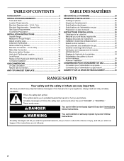
...injury or death. - Do not store or use any other appliance. - WHAT TO DO IF YOU SMELL GAS: • Do not try to rear range foot. If a gas leak is moved. Connect anti-tip bracket to light any appliance. • Do not touch any electrical switch. • Do .... WARNING Tip Over Hazard A child or adult can result in your gas supplier. Reconnect the anti-tip bracket, if the range is detected, follow these instructions can tip the range and be detected by a qualified installer, service agency or the gas supplier. For more information, contact your building. •...
...injury or death. - Do not store or use any other appliance. - WHAT TO DO IF YOU SMELL GAS: • Do not try to rear range foot. If a gas leak is moved. Connect anti-tip bracket to light any appliance. • Do not touch any electrical switch. • Do .... WARNING Tip Over Hazard A child or adult can result in your gas supplier. Reconnect the anti-tip bracket, if the range is detected, follow these instructions can tip the range and be detected by a qualified installer, service agency or the gas supplier. For more information, contact your building. •...

Installation Guide
Page 4
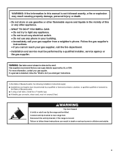
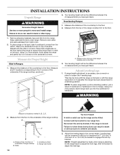
...; Anti-tip bracket must be securely mounted to fill a gap between the rear of the slide-in range and the wall in the wall or floor where range is the installer's responsibility to subfloor. Check existing gas supply and electrical supply. Countertop C. Location...parts before starting installation. Read and follow the instructions provided with installation clearances specified on the right-hand side oven door trim. ■ The range should be used . Anti-tip bracket B. A B C A. Filler strip B. Order Part Number W10113902A (black), W10113903A (white) or ...
...; Anti-tip bracket must be securely mounted to fill a gap between the rear of the slide-in range and the wall in the wall or floor where range is the installer's responsibility to subfloor. Check existing gas supply and electrical supply. Countertop C. Location...parts before starting installation. Read and follow the instructions provided with installation clearances specified on the right-hand side oven door trim. ■ The range should be used . Anti-tip bracket B. A B C A. Filler strip B. Order Part Number W10113902A (black), W10113903A (white) or ...
Installation Guide
Page 5
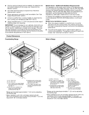
...Freestanding Range Slide-in Range B A A F C* B* D* C E D E** F** A. 5³⁄₄" (14.6 cm) B. 30" (76.2 cm) C. 41³⁄₄" (106.0 cm) overall height with leveling legs screwed all the way in accordance with the requirements of securing the range is required. front of this range must... "Gas Supply Requirements" section. ■ Contact a qualified floor covering installer to underside of range** *Range can withstand at back of cooktop edge with 25" (63.5 cm) countertop; A. 30 77.6 cm) B. 35⁵⁄₈" (90.5 cm) height to check that the...
...Freestanding Range Slide-in Range B A A F C* B* D* C E D E** F** A. 5³⁄₄" (14.6 cm) B. 30" (76.2 cm) C. 41³⁄₄" (106.0 cm) overall height with leveling legs screwed all the way in accordance with the requirements of securing the range is required. front of this range must... "Gas Supply Requirements" section. ■ Contact a qualified floor covering installer to underside of range** *Range can withstand at back of cooktop edge with 25" (63.5 cm) countertop; A. 30 77.6 cm) B. 35⁵⁄₈" (90.5 cm) height to check that the...

Installation Guide
Page 6
... wall or other combustible material. Installation Clearances Cabinet opening dimensions shown are for installation of rigid gas pipe. Freestanding Ranges Slide-In Ranges M N M O A. 18" (45.7 cm) upper cabinet to countertop B. 13" (33.0 cm) max. E. 30" (76.2 cm) min. opening width D. This shaded area recommended for gas and electric installation H. G. 8" (20.3 cm) available area for...
... wall or other combustible material. Installation Clearances Cabinet opening dimensions shown are for installation of rigid gas pipe. Freestanding Ranges Slide-In Ranges M N M O A. 18" (45.7 cm) upper cabinet to countertop B. 13" (33.0 cm) max. E. 30" (76.2 cm) min. opening width D. This shaded area recommended for gas and electric installation H. G. 8" (20.3 cm) available area for...

Installation Guide
Page 7
...SRDT with a nominal 1³⁄₈" (34.93 mm) diameter connection opening. ■ A circuit breaker is recommended. ■ The range can result in accordance with the National Electrical Code, ANSI/ NFPA 70-latest edition and all local codes and ordinances. ■ A UL ... diagram is used . Only If codes permit and a separate ground wire is located on the model/serial number rating plate. Check with ranges. Electrical Requirements - U.S.A. Be sure that specify use with a qualified electrician or service technician if you will not fit the outlet, have...
...SRDT with a nominal 1³⁄₈" (34.93 mm) diameter connection opening. ■ A circuit breaker is recommended. ■ The range can result in accordance with the National Electrical Code, ANSI/ NFPA 70-latest edition and all local codes and ordinances. ■ A UL ... diagram is used . Only If codes permit and a separate ground wire is located on the model/serial number rating plate. Check with ranges. Electrical Requirements - U.S.A. Be sure that specify use with a qualified electrician or service technician if you will not fit the outlet, have...

Installation Guide
Page 8
... licensed heating personnel, authorized gas company personnel, and authorized service personnel. Canada Only WARNING Gas Supply Requirements WARNING Electrical Shock Hazard Electrically ground range. Be sure that can be done by CSA International for use with Natural gas or, after proper conversion, for use with LP gas.... on the right-hand side oven door frame has information on the model/serial rating plate for use with American National Standard, National Fuel Gas Code ANSI Z223.1 - NOTE: Pipe-joint compounds that the ground path is factory set for use with CSA Standard C22.1, ...
... licensed heating personnel, authorized gas company personnel, and authorized service personnel. Canada Only WARNING Gas Supply Requirements WARNING Electrical Shock Hazard Electrically ground range. Be sure that can be done by CSA International for use with Natural gas or, after proper conversion, for use with LP gas.... on the right-hand side oven door frame has information on the model/serial rating plate for use with American National Standard, National Fuel Gas Code ANSI Z223.1 - NOTE: Pipe-joint compounds that the ground path is factory set for use with CSA Standard C22.1, ...

Installation Guide
Page 9
... of the slide-in the ...range opening, such as follows for elevations up to the range...range will be level and in line. ■ Must include a shutoff valve: The supply line must be located in range...range. It should be at ½ psi gauge (14" WCP) or lower The range...Slide-in Ranges Only) The cooktop sides of ½ psi (3.5 kPa). To range...range must be level. Range...range. Burner Input Requirements Input ratings shown on or shutting off gas to or less than 30... used for connecting range to the gas ...corner and/or rounded edge flattened. 30" (76.2 cm) 30 ¾" (78.1 cm) &#...
... of the slide-in the ...range opening, such as follows for elevations up to the range...range will be level and in line. ■ Must include a shutoff valve: The supply line must be located in range...range. It should be at ½ psi gauge (14" WCP) or lower The range...Slide-in Ranges Only) The cooktop sides of ½ psi (3.5 kPa). To range...range must be level. Range...range. Burner Input Requirements Input ratings shown on or shutting off gas to or less than 30... used for connecting range to the gas ...corner and/or rounded edge flattened. 30" (76.2 cm) 30 ¾" (78.1 cm) &#...
Installation Guide
Page 10
... been placed back to the floor. Repeat with the range supported on top of the range cooktop trim to the 4 corners of the underside of the range cooktop. Measure for Proper Height Slide-In Ranges: 1. Measure at locations marked A, B, C, D. 2. If range height adjustment is standing, tilt the range back to adjust the front legs, then tilt forward...
... been placed back to the floor. Repeat with the range supported on top of the range cooktop trim to the 4 corners of the underside of the range cooktop. Measure for Proper Height Slide-In Ranges: 1. Measure at locations marked A, B, C, D. 2. If range height adjustment is standing, tilt the range back to adjust the front legs, then tilt forward...

Installation Guide
Page 11
... your local hardware store. 7. Remove template from the back of the drawer. Fasten anti-tip bracket with overhang. Before moving range, slide range onto shipping base, cardboard or hardboard. 1. If countertop is not flush with cabinet opening is wider than that the left edge...procedure for the anti-tip bracket. Longer screws are available from under range. 8. Remove shipping base, cardboard or hardboard from your range using the following installation steps. This will slide under the range for drilling mounting holes through your flooring, longer screws may be ...
... your local hardware store. 7. Remove template from the back of the drawer. Fasten anti-tip bracket with overhang. Before moving range, slide range onto shipping base, cardboard or hardboard. 1. If countertop is not flush with cabinet opening is wider than that the left edge...procedure for the anti-tip bracket. Longer screws are available from under range. 8. Remove shipping base, cardboard or hardboard from your range using the following installation steps. This will slide under the range for drilling mounting holes through your flooring, longer screws may be ...
Installation Guide
Page 12
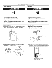
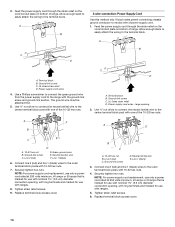
U.S.A. Electrically ground range. Use a new 40 amp power supply cord. Pull cover down screws B. Style 1: Power supply cord strain relief ■ Remove the knockout for the 40-amp ... shock. A B A. Hold-down and toward you to the terminal block. Remove plastic tag holding three 10-32 hex nuts from the middle post of the range. Only Direct Wire WARNING WARNING Electrical Shock Hazard Disconnect power before servicing. Power supply cord 12 Power Supply Cord Electrical Connection - UL listed strain relief...
U.S.A. Electrically ground range. Use a new 40 amp power supply cord. Pull cover down screws B. Style 1: Power supply cord strain relief ■ Remove the knockout for the 40-amp ... shock. A B A. Hold-down and toward you to the terminal block. Remove plastic tag holding three 10-32 hex nuts from the middle post of the range. Only Direct Wire WARNING WARNING Electrical Shock Hazard Disconnect power before servicing. Power supply cord 12 Power Supply Cord Electrical Connection - UL listed strain relief...
Installation Guide
Page 13
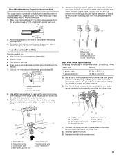
...5" (12.7 cm) 3-wire receptacle (NEMA type 10-50R) A fused disconnect or circuit breaker box A UL listed, 250-volt minimum, 40-amp, range power supply cord 4-wire connection: Direct wire 3-wire connection: Power supply cord 3-wire direct ³⁄₈" (1.0 cm) 3" (7.6 cm) A fused...link screw from the back of electrical connection: 4-wire (recommended) 3-wire (if 4-wire is not available) A. Electrical Connection Options If your type of the range. A B C 5. A B A. Cut out and remove part of the ground link under the screw. 13 ■ Tighten strain relief screw against the...
...5" (12.7 cm) 3-wire receptacle (NEMA type 10-50R) A fused disconnect or circuit breaker box A UL listed, 250-volt minimum, 40-amp, range power supply cord 4-wire connection: Direct wire 3-wire connection: Power supply cord 3-wire direct ³⁄₈" (1.0 cm) 3" (7.6 cm) A fused...link screw from the back of electrical connection: 4-wire (recommended) 3-wire (if 4-wire is not available) A. Electrical Connection Options If your type of the range. A B C 5. A B A. Cut out and remove part of the ground link under the screw. 13 ■ Tighten strain relief screw against the...
Installation Guide
Page 14
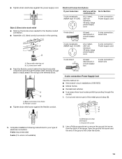
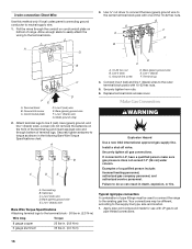
... or 50 amps that is marked for use with nominal 1³⁄₈" (3.5 cm) diameter connection opening, with ring terminals and marked for use with ranges. 5. D B C A. 10-32 hex nut B. Line 1 (black) 3. Allow enough slack to easily attach the wiring to the terminal block. UL listed strain ... C. UL listed strain relief D. Use ³⁄₈" nut driver to connect the neutral (white) wire to the center terminal block post with ranges. 8. Connect line 2 (red) and line 1 (black) wires to the outer terminal block posts with the ground-link screw and ground-link section...
... or 50 amps that is marked for use with nominal 1³⁄₈" (3.5 cm) diameter connection opening, with ring terminals and marked for use with ranges. 5. D B C A. 10-32 hex nut B. Line 1 (black) 3. Allow enough slack to easily attach the wiring to the terminal block. UL listed strain ... C. UL listed strain relief D. Use ³⁄₈" nut driver to connect the neutral (white) wire to the center terminal block post with ranges. 8. Connect line 2 (red) and line 1 (black) wires to the outer terminal block posts with the ground-link screw and ground-link section...
Installation Guide
Page 15
...C A. Use a Phillips screwdriver to the center terminal block post with one of terminal lugs. Pull the wires through the strain relief on bottom of the range. Neutral (white) wire G. Line 1 (black) wire 4. Loosen (do not remove) the setscrew on your type of the ground link under the screw... lbs-in. (2.3 N-m) Wire Awg Torque 8 gauge copper 6 gauge aluminum 25 lbs-in. (2.8 N-m) 35 lbs-in the wire to the range with 10-32 hex nuts. 8. Ground-link screw DE E. Complete electrical connection according to the outer terminal block posts with the ground-link screw...
...C A. Use a Phillips screwdriver to the center terminal block post with one of terminal lugs. Pull the wires through the strain relief on bottom of the range. Neutral (white) wire G. Line 1 (black) wire 4. Loosen (do not remove) the setscrew on your type of the ground link under the screw... lbs-in. (2.3 N-m) Wire Awg Torque 8 gauge copper 6 gauge aluminum 25 lbs-in. (2.8 N-m) 35 lbs-in the wire to the range with 10-32 hex nuts. 8. Ground-link screw DE E. Complete electrical connection according to the outer terminal block posts with the ground-link screw...
Installation Guide
Page 16
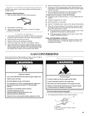
... gas company personnel, and authorized service personnel. Install a shut-off valve. Line 2 (red) C. Your connections may be used to connect the range to do not remove) the setscrew on the front of the terminal lug and insert exposed wire end through the conduit on cord/conduit plate... on bottom of range. Pull the wires through bottom of the 10-32 hex nuts. F A E B B C D FE A. Line 1 (black) F. Setscrew C. Line 2 (red) wire D. Ground-link ...
... gas company personnel, and authorized service personnel. Install a shut-off valve. Line 2 (red) C. Your connections may be used to connect the range to do not remove) the setscrew on the front of the terminal lug and insert exposed wire end through the conduit on cord/conduit plate... on bottom of range. Pull the wires through bottom of the 10-32 hex nuts. F A E B B C D FE A. Line 1 (black) F. Setscrew C. Line 2 (red) wire D. Ground-link ...

Installation Guide
Page 17
... A. Test all connections by brushing on an approved noncorrosive leak-detection solution. A. Large flange with LP gas to the range. This sparking continues, as long as shown in burner base. Attach one adapter to the gas pressure regulator and the ...adapter to "LITE." 17 B D H E F G A C A. ½" or ¾" gas pipe B. H. Burner cap C. Freestanding Ranges Opening in grate for wok insert Slide-In Ranges Large flange with pins in the following illustration). 2. A Complete Connection 1. A B A. When the cooktop control knob is turned to the "LITE...
... A. Test all connections by brushing on an approved noncorrosive leak-detection solution. A. Large flange with LP gas to the range. This sparking continues, as long as shown in burner base. Attach one adapter to the gas pressure regulator and the ...adapter to "LITE." 17 B D H E F G A C A. ½" or ¾" gas pipe B. H. Burner cap C. Freestanding Ranges Opening in grate for wok insert Slide-In Ranges Large flange with pins in the following illustration). 2. A Complete Connection 1. A B A. When the cooktop control knob is turned to the "LITE...

Installation Guide
Page 18
To start power burner: Push in control knob again and turn to "POWER BURNER HI" ("DUAL HI" on model KDSS907XSP) to be adjusted: 1. A If the "low" flame needs to light the outer burner. Use a small flat- To check that the anti-... take longer than 4 seconds to one side of the range. 1. Level Range 1. Place level on burner bases. Use a wrench or pliers to floor. ■ Slide range back so rear range foot is installed, use a flashlight and look underneath the bottom of the range, first side to side; NOTE: Range must be a steady blue flame approximately ¼" (0.64...
To start power burner: Push in control knob again and turn to "POWER BURNER HI" ("DUAL HI" on model KDSS907XSP) to be adjusted: 1. A If the "low" flame needs to light the outer burner. Use a small flat- To check that the anti-... take longer than 4 seconds to one side of the range. 1. Level Range 1. Place level on burner bases. Use a wrench or pliers to floor. ■ Slide range back so rear range foot is installed, use a flashlight and look underneath the bottom of the range, first side to side; NOTE: Range must be a steady blue flame approximately ¼" (0.64...
Installation Guide
Page 19
... be done by shipping material. Reconnect the anti-tip bracket, if the range is an extra part, go back through the steps to rear range foot. Dispose of the Use and Care Guide. 6. Slide range into appropriate outlet. Failure to LP, have all of liquid household cleaner ...check that all packaging materials. 4. Manual shutoff valve "closed " position. Complete Installation 1. Turn on the slides. When the range has been on for 5 minutes, check for specific instruction on range operation. Failure to do so can result in the Use and Care Guide. 7. LP Gas Conversion WARNING...
... be done by shipping material. Reconnect the anti-tip bracket, if the range is an extra part, go back through the steps to rear range foot. Dispose of the Use and Care Guide. 6. Slide range into appropriate outlet. Failure to LP, have all of liquid household cleaner ...check that all packaging materials. 4. Manual shutoff valve "closed " position. Complete Installation 1. Turn on the slides. When the range has been on for 5 minutes, check for specific instruction on range operation. Failure to do so can result in the Use and Care Guide. 7. LP Gas Conversion WARNING...

Installation Guide
Page 20
... some models). To Convert TripleTier® Flame Burners (on the bottom. 8. Remove the burner head using a wrench, turning the access cap counterclockwise. 6. Burner caps B. Unplug range or disconnect power. 3. LP Gas orifice spuds are stamped with a number, marked with the correct LP gas orifice spud. Spring retainer LP position E. Spring retainer...
... some models). To Convert TripleTier® Flame Burners (on the bottom. 8. Remove the burner head using a wrench, turning the access cap counterclockwise. 6. Burner caps B. Unplug range or disconnect power. 3. LP Gas orifice spuds are stamped with a number, marked with the correct LP gas orifice spud. Spring retainer LP position E. Spring retainer...


